Page 6 of 10 FirstFirst ... 3456789 ... LastLast
Results 126 to 150 of 250

Thread: Project Quintessence

  1. #126
    I am Xtreme
    Join Date
    Jun 2007
    Location
    Imperial Palace, UDE of Pitatopia
    Posts
    8,396
    Wow, your sketchup skills are getting good to, had me fooled for a few seconds thinking the case was done.

    Nice to see you came back to LC for this, I don't think you would have been happy with air.

    Nice job on the fix, keep up the good work voigts.

    As always. . .
    Circles SucQ!

    If your annoyed by sigs telling you to put things in your sig, then put this in your sig

    Bribery won't work on me...just say NO to AT!!!

  2. #127
    Moderator
    Join Date
    Aug 2007
    Location
    Back and forth between Florida and Maine
    Posts
    4,097
    After much messing around in Sketchup, I've finally come to the conlusion that I am going to watercool it
    YIPPEE ... making a great project even better.

    (umm ... I can delete the OT posting in your worklog tomorrow ... don't want to clutter up your nice work )

  3. #128
    Xtreme Addict
    Join Date
    Feb 2005
    Location
    Tennessee
    Posts
    1,171
    Quote Originally Posted by Waterlogged View Post
    Wow, your sketchup skills are getting good to, had me fooled for a few seconds thinking the case was done.

    Nice to see you came back to LC for this, I don't think you would have been happy with air.

    Nice job on the fix, keep up the good work voigts.

    As always. . .
    I need to take the time to really figure out better how to deal with materials in Indigo to make them more realistic. I just haven't applied myself to figuring it out yet. I really am surprised however at how easy it is with little knowledge to get a decent basic render though. I try Kerkythea, but I just had a hard time with it for whatever reason.

    As for the air, not being happy with it is THE reason I decided to stay with water. After being on water for so long, I just am not sure that I will get a quiet/performance level I'll be satisfied with on air.

    Quote Originally Posted by shazza View Post
    YIPPEE ... making a great project even better.

    (umm ... I can delete the OT posting in your worklog tomorrow ... don't want to clutter up your nice work )
    Thanks Sharon.

    I guess since you are an admin now, you can delete whatever you want, right?

  4. #129
    Xtreme Addict
    Join Date
    Nov 2009
    Location
    Netherlands
    Posts
    1,884
    It's good to see you decided to watercool it anyway . Air would've been nice, but you have the room for watercooling, so why not? .
    And yes, finding that picture took some digging, about 10-15 pages. But reading through the log again, I can't wait 'till you get back to modding Sharon .
    “Little expense had been spared to create the impression that no expense had been spared.” - Hitchhiker's Guide
    It's better to ask dumb questions now, than to look stupid later
    Mondays:

  5. #130
    Xtreme Addict
    Join Date
    Feb 2005
    Location
    Tennessee
    Posts
    1,171
    I spent some time last night playing around in Skindigo (Indigo Renderer) downloading, applying, and tweaking some materials, and made a couple of better renders. I do plan on using a copper hammertone paint for the aluminum that will be very similar to that pictured in these renders, just with less black. Mind you I'm still taking baby steps here, but what do you guys think?


    I did some bits and pieces today like moving the hard drive mount closer to the rear of the case, repositioning the hard drives fan mount, and making the spacers for the front trim and front panel, but nothing really to take pics of much.

  6. #131
    Xtreme Addict
    Join Date
    Feb 2005
    Location
    Tennessee
    Posts
    1,171
    Top and Front Panels Cut and Mounted

    This is the kind of update that you like to have when you finally have some pieces together that look like something. I got the edge moulding pieces mounted and cut to length, got the front panel cut to length and mounted to the case, and the top panel cut and mounted. To mount the edge molding to the top, I used a number of tiny countersunk 1/4” (6.35mm) long #4 screws.


    It took me about an hour using a table saw to cut the center area out of the top panel as I don't yet have a dado cutting plate for my table saw, so I had to go at it little by little. I tried using a router, but it had the tendency to grab the fretwork and chip it. Once the top panel was grooved out, it wanted to bow as I expected seeing as it was only 3/8” (about 9.5mm) thick now except for the edges. I screwed two aluminum pieces to the top panel to straighten out the bowing.


    In order to get the contour of the front of the top piece to match the front panel, I mounted the front panel and top panel via screws, and scribed the contour of the front onto the top piece. The top panel was loose here. There is no gap once screwed down.


    I then cut it out with the scroll saw.


    Here are a couple of shots of where things are so far. I still have to sand and fine tune the contour of the front of the top panel to match the front panel.


    I also picked up a new tool which has proven itself quite handy. This little thing has a surprising amount of torque. It has come in very handy in that it can screw so close next to things. This saved me in several tight spots using a countersink bit for screws.


    As I mentioned, I have to fine tune the front of the top panel to match the contour of the front panel. I also have to route a 1/8” (3.17mm) curve on the edges of the top. Then its on to cutting out the base, and then on to the sides and more scrolling action.

    Thanks for stopping by.

  7. #132
    Moderator
    Join Date
    Aug 2007
    Location
    Back and forth between Florida and Maine
    Posts
    4,097
    Wowser, stopped in to do a bit of clean-up, and saw this nice update. You're making great progress, Voigts!

  8. #133
    Xtreme Member
    Join Date
    Nov 2008
    Location
    Eagle Rock, Ca.
    Posts
    398
    Quote Originally Posted by shazza View Post
    ...You're making great progress, Voigts!
    +1

    I may not always login and post but I'm always watching, Gary.
    This is one of those worklogs that I truly enjoy watching.

    All the skill, knowledge, experience, and talent that [went/is still going] into that exquisite front panel alone is just plain sickening.

    Cheers, me hearty!

  9. #134
    Xtreme Addict
    Join Date
    Feb 2005
    Location
    Tennessee
    Posts
    1,171
    Quote Originally Posted by shazza View Post
    Wowser, stopped in to do a bit of clean-up, and saw this nice update. You're making great progress, Voigts!
    Thanks Sharon. I'm really trying to get this project moving along as it has been sitting far too long. I hardly got anything done on it this summer.

    Quote Originally Posted by CptDreadFlint View Post
    +1

    I may not always login and post but I'm always watching, Gary.
    This is one of those worklogs that I truly enjoy watching.

    All the skill, knowledge, experience, and talent that [went/is still going] into that exquisite front panel alone is just plain sickening.

    Cheers, me hearty!
    Thanks a lot Rick. I appreciate knowing you are checking in.

    Now go back to your rum bottle and attacking some more innocent victims...

  10. #135
    Xtreme Addict
    Join Date
    Feb 2005
    Location
    Tennessee
    Posts
    1,171
    Top Panel Front Sanded Flush and Base Cut and Mounted

    I worked on the top a bit and put brass threaded inserts into the screw holes that attach the top to the frame so that I could use machine screws instead of wood screws to hold the top down. I also got the front of the top panel sanded flush with the front, and got the base cut out and mounted. I have to round the edges of the top panel, and I've got to tweak the base a bit as well as the top trim and a few other things.There are small gaps and such that I need to address. It is so easy to be just the tiniest bit off on joints and such. I then can cut out and start on the side panels. At least the scrollwork on the side panels should be a piece of cake cutting into and sanding 1/4” (6.35mm) oak plywood vs 1 1/2” (38mm) of solid oak.


    Thanks for stopping by.

  11. #136
    Xtreme Addict
    Join Date
    Feb 2005
    Location
    Tennessee
    Posts
    1,171
    Edges of Top Panel Routed & Various Adjustments

    I got the edges of the top panel routed with a 1/8” roundover bit.


    I spent several hours doing little bits and pieces adjustments that needed to be done in order for things to fit correctly. For instance, I sawed down the thickness of the base on the right side so that the bottom radiator will fit in the bottom. I also had to make several adjustments to the bottom of the metal frame and the separate radiator mounting piece to make sure the holes line up properly with the rad mount holes.


    I was having an issue with the top panel where it did not quite want to sit flush against the top of the front panel. There was just a slight gap. I added a couple of pieces to the top panel to make it rest against the metal of the frame with a brass screw insert so that I can use a machine screw to secure the middle area of the front of the top panel to the top of the front panel to eliminate the small gap.


    I also had a slight gap between the base sides and the base front. I made my own little mending brackets out of aluminum, and used a Dremel to hack out small grooves for them to sit in so that they don't protrude from the bottom. I wasn't too concerned with making the grooves really neat as they are on the bottom of the case and will be covered by felt cushion anyway.


    I was having some issues with the edge trim on the top edges not being held down very securely. I used #4 x 1/4” flathead screws, but they just weren't holding well. I've found before that #2 x 1/4” screws hold better, and should have used them the first time. Using JB weld I filled in the countersunk holes in the case top, and drilled new holes using round head #2 x 1/4” screws. I am going to paint or powdercoat the metal part of the case anyway, so a bit of JB Weld is not a problem. The #2 screws really secure the edge mouldings much better.


    I think next I will work on the power buttons, and then it should be on to the sides or either the reservoir depending on what strikes my fancy to get done next.

    Thanks for stopping by.

  12. #137
    Xtreme Addict
    Join Date
    Feb 2005
    Location
    Tennessee
    Posts
    1,171
    Top Panel Brass Inserts

    As I mentioned, I want the front panel to be removable if the need should arise. To keep the possibility of wood screw threads stripping out, I put #6-32 brass threaded inserts into the holes. This proves itself to be no piece of cake. I drilled the largest hole I can and still be able to thread in the inserts, and even at that, the screwdriver cut parts break off. It took me about an hour and about 8 inserts to successfully get the 4 inserts in.


    Power and Reset Switches

    I had to work a bit to figure out how to mount the power and reset switches. I decided to make a small mount piece to attach to the bottom of the case in which to mount the switches. I took the front piece off, and using my drill press, drilled two straight holes for the center of the switches.


    To make sure I got the holes on the front to line up with the switches mount, I put back on the front and drilled through the front panel holes into the switches mount.


    I wanted to try to match the grain of the front panel on the power/reset buttons. I took an end of the front piece that I cut off earlier when I trimmed it down to length, and measured and cut out two power buttons. This way the grain would match fairly well, and the curve of the buttons matches the front.


    The buttons will set flush with the front when installed later.


    Radiator Drain Screw

    I think that the Swiftech MCR rads are the best bang for the buck around. One small beef I have with them is that I wish they had a drain screw on the end. I needed a drain at the bottom of my loop, and having one in the bottom rad is the best solution. So I decided to add one to my bottom MCR220 rad.

    I sanded the paint off of the bottom, and drilled a 1/8” hole in the bottom. You have to be very careful here when the drill bit goes through the metal not to jab the drill bit into the internal radiator tubes.


    I clamped the rad so that it wouldn't wander around on me.


    Soldering anything like this is a bit tricky. If you heat up the rad too much, you risk messing up the solder joints on the rad. I took a #8 brass nut, rounded off the corners, and put plenty of flux on it and the rad around the hole I had drilled. I put a cold, damp washcloth around the solder joint on the end tank.


    MAPP gas burns a lot hotter than plain butane, and this is all I will use anymore when soldering. It burns hot enough that you can heat up just the area to be soldered, and the wet cloth helps keep the surrounding area just below the temp where solder flows. Its a bit tricky. At first, the flux partially burned out of the area, and I had to quickly brush on a large gob of flux and solder some more to get the solder to flow around the nut. Thankfully it seems to have worked. This is right after soldering.


    I used my Dremel and ground down the solder to make it look more even. I didnt want to grind too far and weaken the joint, but just enough to even up the solder as much as possible.


    I cut off a #6-32 brass screw short to just thread through the now soldered on nut. I'm not sure the rubber washer is going to seal the drain screw well enough, so I plan on picking up an o-ring tomorrow for this. I still have to pressure test the rad to make sure all is well.

    Reservoir Plans

    I nailed down exactly how I'm going to make the reservoir, and made some alphabet and color coded Sketchup drawings so I hopefully don't make any stupid mistakes. Its amazing how you can get twisted up when you are in the heat of things sometimes. The idea with the res is the the water has to go from the inlet on the side up to the rear of the res, up the angled piece, and then down into the outlet on the bottom. My thought is that this will provide ample opportunity for air to work toward the top.


    As usual, thanks for stopping by.

  13. #138
    Xtreme Addict
    Join Date
    Feb 2005
    Location
    Tennessee
    Posts
    1,171
    That's what I should have done. Fiddling with the #6 inserts isn't worth the hassle.

  14. #139
    I am Xtreme
    Join Date
    Jun 2007
    Location
    Imperial Palace, UDE of Pitatopia
    Posts
    8,396


    Keep it up voigts.
    Circles SucQ!

    If your annoyed by sigs telling you to put things in your sig, then put this in your sig

    Bribery won't work on me...just say NO to AT!!!

  15. #140
    Xtreme Addict
    Join Date
    Feb 2005
    Location
    Tennessee
    Posts
    1,171
    Quote Originally Posted by Waterlogged View Post


    Keep it up voigts.
    Thanks Waterlogged. Its good to know I'm not alone out here.


    Radiator Leaktested

    After soldering the drain on the radiator, I thought it wise to make sure nothing got messed up in the process internally that could cause a leak. I replaced the rubber washer on the drain screw with an o-ring as the washer wasn't tight enough. I hooked the radiator up to my gauge, pumped it up to 9psi, and watched. I'm very glad to say that there are no leaks.


    Bottom Radiator Mount Remade

    I started thinking more about airflow, and decided that I could have the bottom radiator push air from inside the case out the bottom. To do this, I would need to change the bottom rad mount. I wasn't really pleased with the bottom mount, so instead of modifying it, I decided to scrap it and make another one, this time out of 14 gauge aluminum instead of 16 gauge. I used the dual rad template from MNPCtech, and the bottom mount turned out much, much better than the first one had. This was a few hours worth of work.

    Here is a shot of mount with just the radiator mounted.


    Here is another with a couple of old fans mounted just to make sure everything is good.


    I still need to make something to dress up the fans a bit.

    Bottom Radiator Airflow Piece

    In having the bottom radiator vent out of the bottom of the case, I needed some way to direct the air out of the back of the underside of the case without it getting sucked back into the case. I made this airflow piece to mount to the bottom of the case. This piece was bit of a pain as I couldn't use my metal bender to do all of the bends, and had to bend them over the edge of my table saw with a hammer. This piece took a couple of hours to get right. These little things can take so much time.


    Front Panel Trim Template

    I also printed out a template of the front panel trim piece, and glued it to a piece of 1/4” oak that I have that is cupped a bit, which will help with getting it to match the curve of the front panel. A friend of mine who does a lot of scrollsaw stuff gave me the idea of using blue painter's tape, putting it on the wood, then spray gluing the template to the tape. This way there is no sanding to get the glue off once the shape is cut out. I bought 2” wide blue painter's tape for this.


    I also got most of the reservoir pieces cut out on the table saw today. Having new aluminum/acrylic saw blades is wonderful. The cuts come out so clean compared to using plywood blades. The reservoir and front trim piece are next on my list to be completed. I also have to figure exactly how I'm going to mount the USB port on the front part of the left side.

    Thanks for stopping by.
    Last edited by voigts; 02-14-2011 at 10:55 PM.

  16. #141
    I am Xtreme
    Join Date
    Jun 2007
    Location
    Imperial Palace, UDE of Pitatopia
    Posts
    8,396
    I always poke my head in when I see an update voigts. Just too busy enjoying the popcorn to post every time.

    Me likey the new bottom rad mount, really clean looking.
    Circles SucQ!

    If your annoyed by sigs telling you to put things in your sig, then put this in your sig

    Bribery won't work on me...just say NO to AT!!!

  17. #142
    Xtreme Member
    Join Date
    Nov 2008
    Location
    Eagle Rock, Ca.
    Posts
    398
    Quote Originally Posted by Waterlogged View Post
    ...just too busy enjoying the popcorn to post every time...
    This.
    Except Rum may sometimes deter me from replying at times.

    Digging how the pwr and reset buttons came out and your plans for your res is looking fantastic! I'm excited to see more.

    Keep up the fantastic work, Gary.

  18. #143
    Xtreme Addict
    Join Date
    Feb 2005
    Location
    Tennessee
    Posts
    1,171
    Quote Originally Posted by Waterlogged View Post
    I always poke my head in when I see an update voigts. Just too busy enjoying the popcorn to post every time.

    Me likey the new bottom rad mount, really clean looking.
    Thanks Waterlogged. I'm very satisfied with the revised bottom mount. It came out the way I wanted.

    Quote Originally Posted by CptDreadFlint View Post
    This.
    Except Rum may sometimes deter me from replying at times.

    Digging how the pwr and reset buttons came out and your plans for your res is looking fantastic! I'm excited to see more.

    Keep up the fantastic work, Gary.
    Thanks Rick. I'm hoping to work on the res some more today.

    If that pirate rum keeps you from replying, what else have you been missing? Now I know why your mod has kind of stalled lately.

  19. #144
    Moderator
    Join Date
    Aug 2007
    Location
    Back and forth between Florida and Maine
    Posts
    4,097
    Yep ... another nice update. (I do repeat myself, sorry .

    This is my favorite build going. So glad you also decided to add water!

  20. #145
    Xtreme Addict
    Join Date
    Nov 2009
    Location
    Netherlands
    Posts
    1,884
    Ooh, 2 updates since I've been busy! Looks great, keep up the good work .
    “Little expense had been spared to create the impression that no expense had been spared.” - Hitchhiker's Guide
    It's better to ask dumb questions now, than to look stupid later
    Mondays:

  21. #146
    Xtreme Addict
    Join Date
    Feb 2005
    Location
    Tennessee
    Posts
    1,171
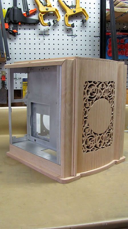
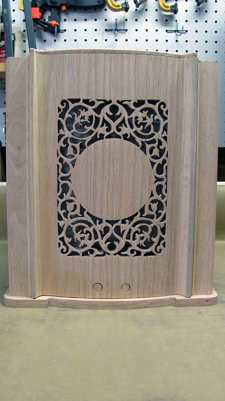
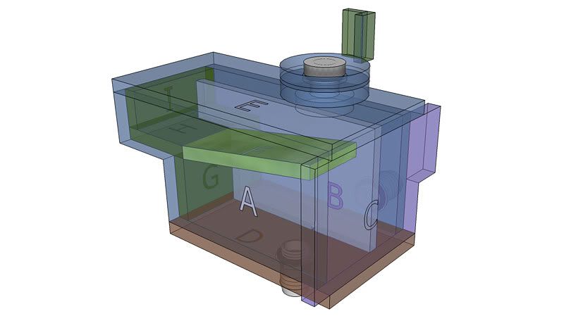
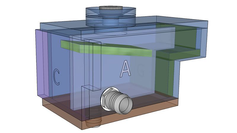
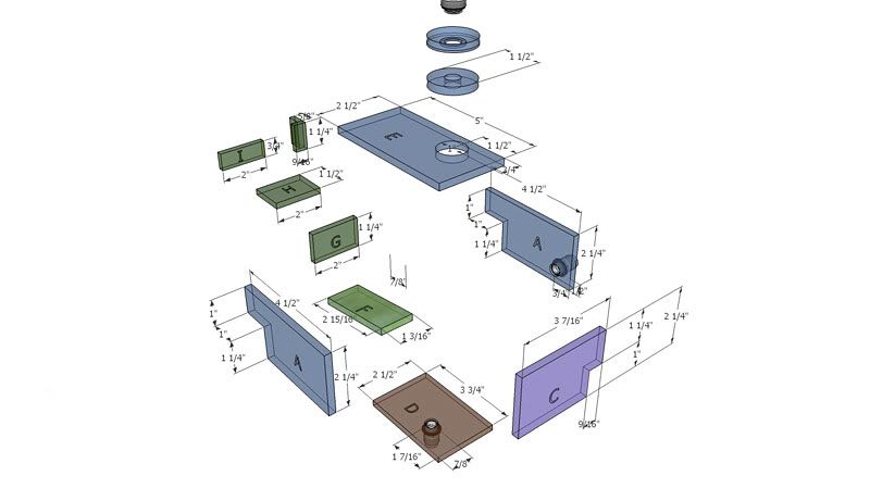
    Making the Reservoir

    Part of making custom cases with watercooling is that you run into situations where out-of-the-box reservoirs simply may not fit or work well. I personally do not like T-lines, and so stick with reservoirs. I designed this build to continue using my Aquastream XT Ultra, which has necessitated that I come up with a custom reservoir that will fit the case. I also find that being able to customize my own reservoirs allows me to route the loop how I want, not how a reservoir may dictate due to its limited options. That being said, making a cylindrical reservoir is far easier than making a rectangular one.

    Tips for Making a Rectangular Acrylic Reservoir

    I am by no means some kind of expert at working with acrylic, and there are others that do a lot more with acrylic than I ever hope to. I do however have some things I can share that I've figured out via trial and error that have helped me.

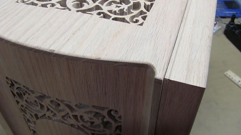
    1. The type and thickness of acrylic are important for reservoirs. I would not even attempt this using extruded acrylic. Extruded acrylic is far too soft to machine well, and crazes far too easily (crazing is cracking that occurs when acrylic is stressed too much). I only use 1/4” cast acrylic. Cast acrylic is much harder, and machines very similarly to wood.

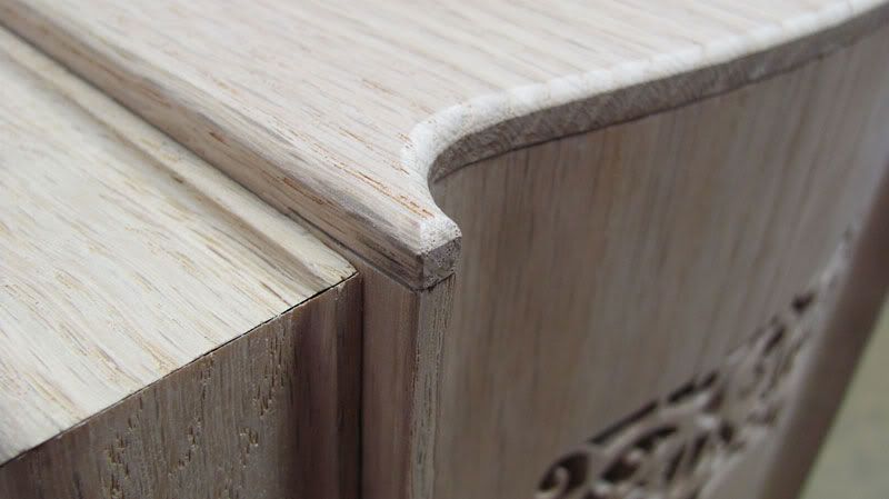
    2. A rectangular reservoir requires very precise, smooth cuts in order for the joints to weld properly. The ultimate here would be to have access to a laser cutter. Acrylic pieces cut with a laser are perfectly dimensioned, and have perfectly smooth, clean edges. I have a very good table saw with an aluminum/acrylic hollow ground blade. This blade makes very clean cuts that are smooth enough to solvent weld without any sanding. You can also cut pieces with a simple hand held miter box. Trying to use plywood saw blades on a table or miter saw scratches up the acrylic edges too much requiring sanding. It is hard to sand edges and not get them out of square.

    3. When it comes to sanding edges, I do not machine sand any edge that I'm going to solvent weld. Sanding heats up acrylic a lot, and if edges that are machine sanded are later solvent welded, they tend to craze. I only hand sand any edges I have to, including any exterior edges that are not directly being welded.

    4. Weld-on #3, or Tap Plastics solvent (basically the same thing) are my weapons of choice. This solvent is like water, but when used, produces very strong joints.

    5. Smooth, accurate edges produce strong, tight solvent welds.

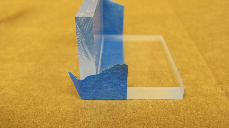
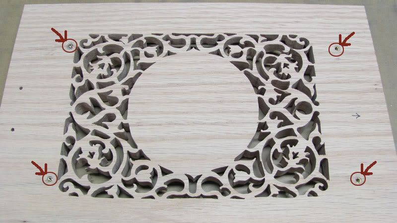
    6. Plan your reservoir around making mistakes. I know that anything I cut with my table saw is going to be very accurate, so any rectangular piece is going to be spot on. With this reservoir however, I had to cut a piece out of the rectangular sides to form a kind of L shape. I therefore made the L shaped sides as the outside most pieces so that if the part I cut out is a bit off, it doesn't matter.

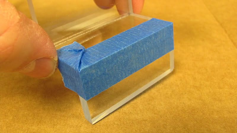
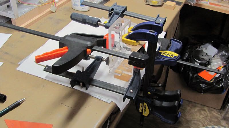
    7. When solvent welding joints, I use 3M painter's tape to hold the joints together. Don't use cheap tape here. The painter's tape holds the joint just the way you want, and it also keeps the solvent from running out of the joint.
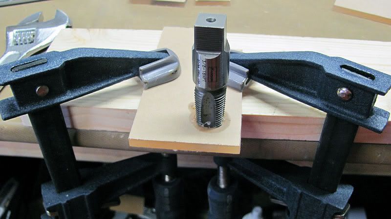
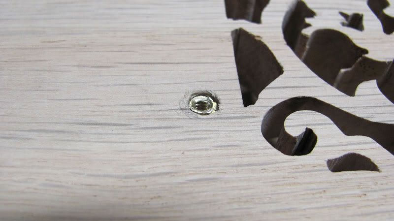
    8. You can use a tap and make G1/4” threaded holes for use with metal fittings. I'm using a G1/4” plug for the top of the res. This works OK as long as the metal fittings aren't tightened too much. Over-tightening will cause crazing in the acrylic. I prefer however to use plastic barbs/fittings as they put very little stress on the acrylic. I used 3/8”NPT threaded black plastic barbs sealed with silicone for this res.

    With all of this said, on to the pics. I of course first cut out all of my pieces on my table saw. I used my scroll saw with the rpms turned down slow to cut out the sides into their L shape.

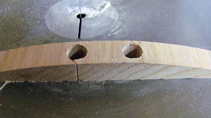
    Before I put any pieces together, I drilled the necessary holes and tapped the threads I needed. This is a lot easier to do before you start putting pieces together. The shavings can also find their way into corners of the res where you don't want them if you tap the threads after putting together the res. I usually use silicone spray to lubricate the tap for acrylic.


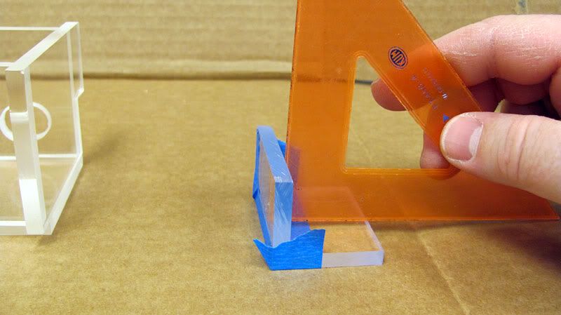
    Using a triangle square, I started solvent welding the pieces together.


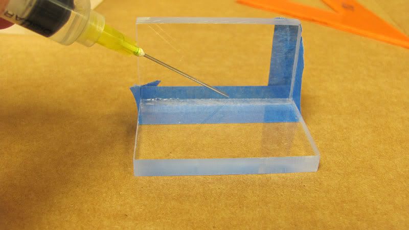
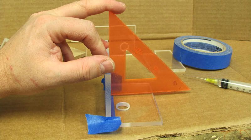
    The method of joining I am using here is called capillary solvent welding. This is yielding me some very smooth, strong joints. The little bit of bubbling you see is nothing to be concerned about. I like the 1/4” thickness of the acrylic as it is far more forgiving of minor flaws than say 1/8” would be.


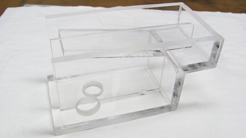
    Here is a shot with everything but the front and top on. I decided to glue the top on and then the front as this afforded me the easiest way to get solvent into the joints using the barb holes.


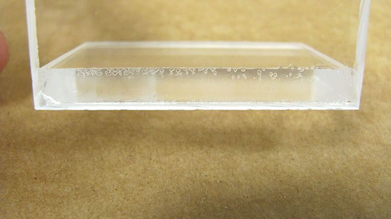
    After everything was together, I clamped the res. This helps eliminate any air bubbles in the joints. You want to stick to clamping down the edges, and not clamping down too tightly. You don't want to tighten the clamps like a gorilla, particularly away from the edge, and craze the acrylic.


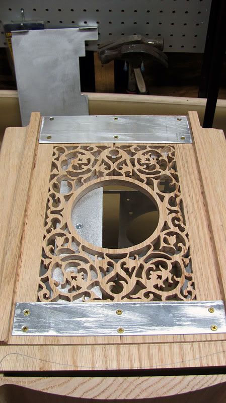
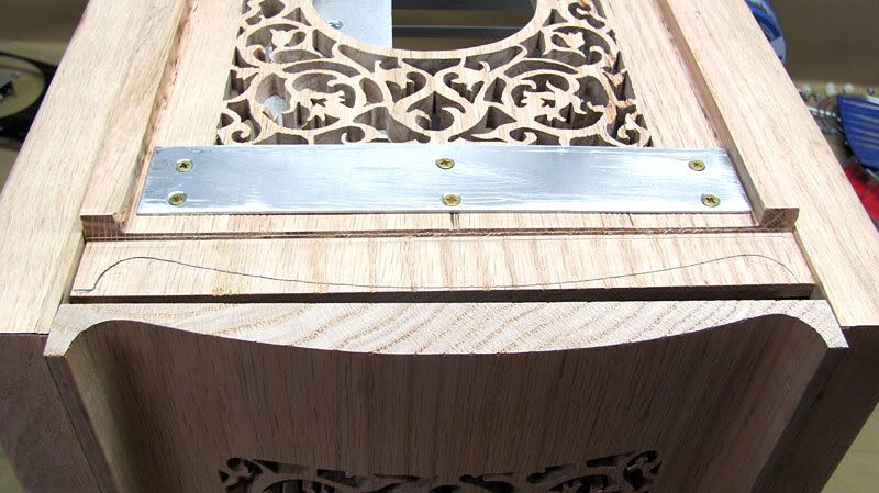
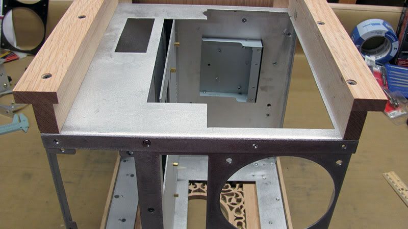
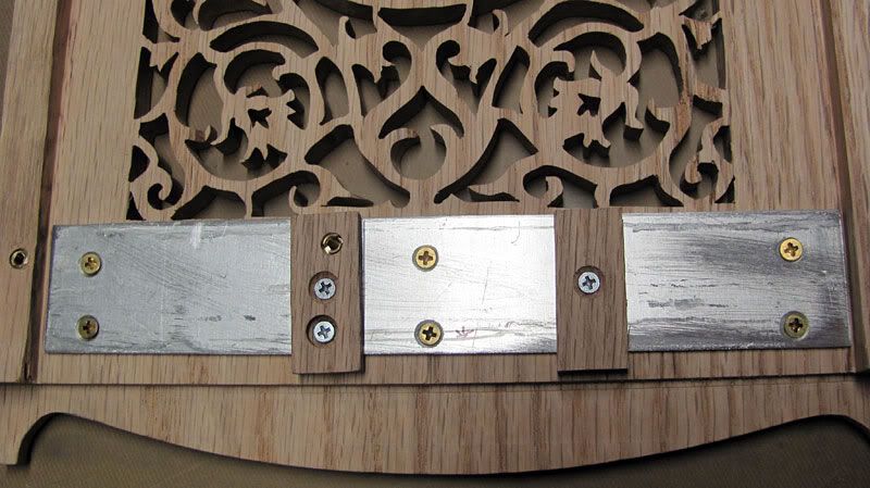
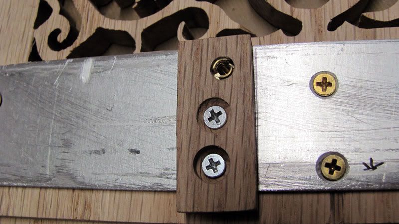
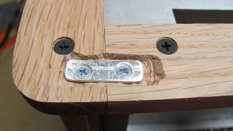
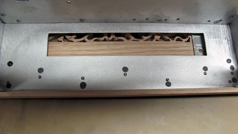
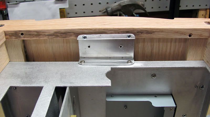
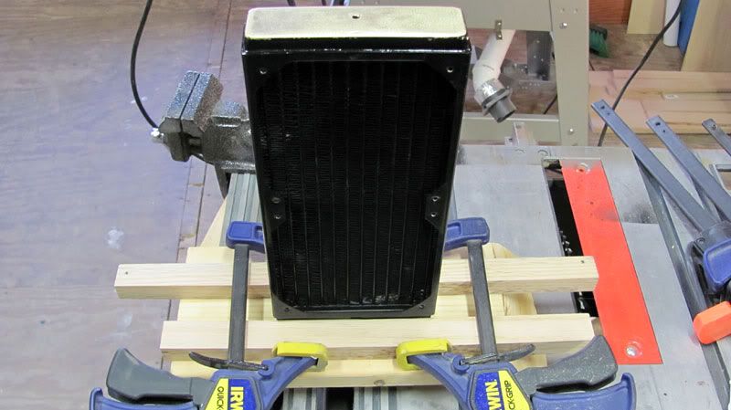
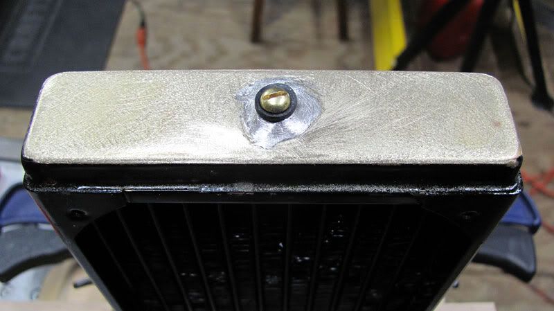
    Here is the res mounted. I still need to clean it out in case you are wondering. Note that I'm using o-rings and a rubber washer on the mounting screws where they touch the acrylic to make sure I don't craze the acrylic. The two side screws go through the metal front into the wooden corner.


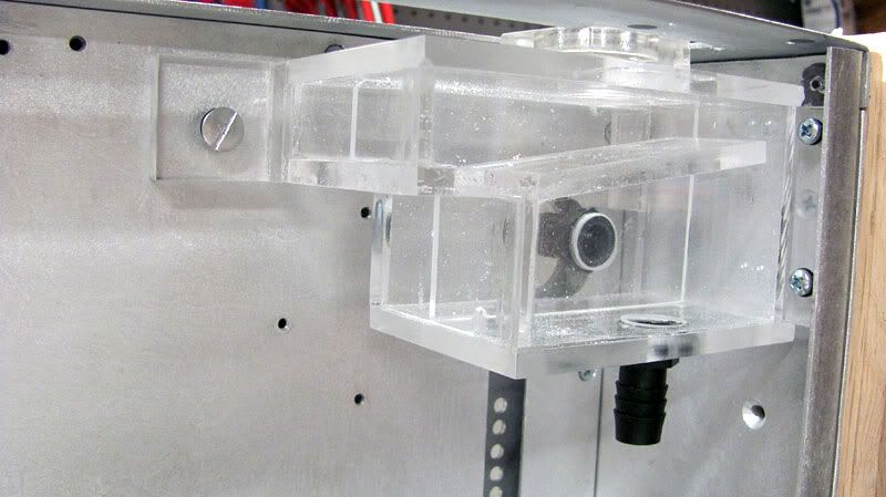
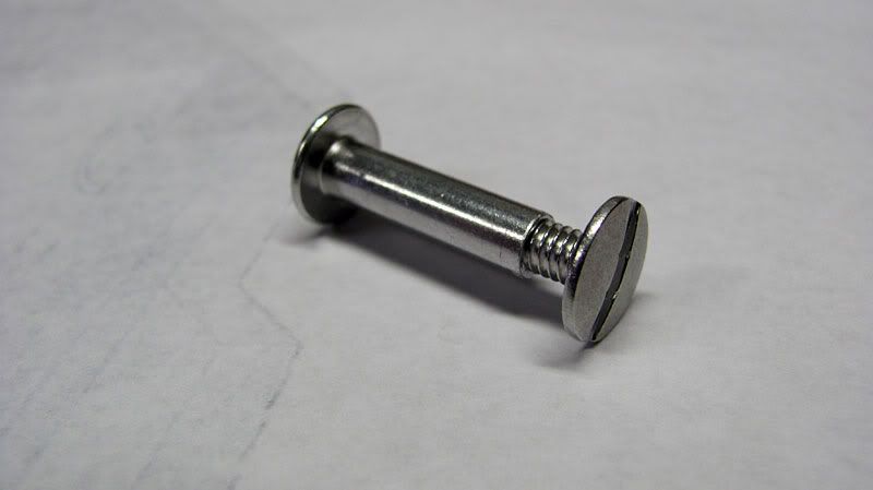
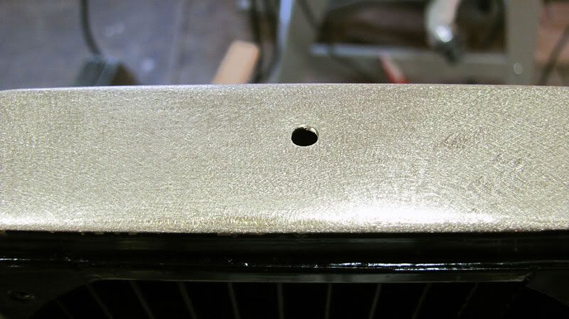
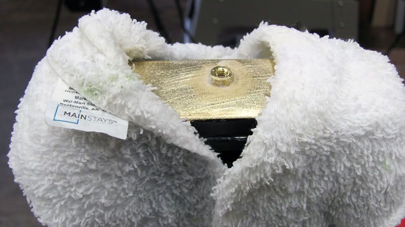
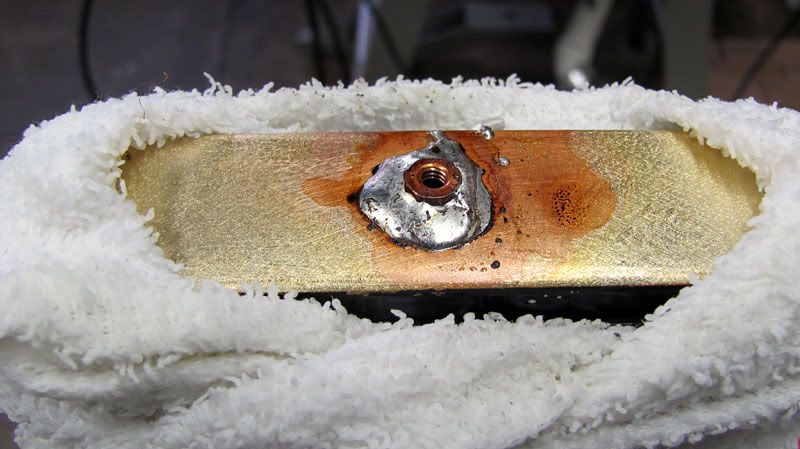
    For the part of the res that is mounted to the PSU panel, instead of using a metal screw which doesn't hold that tightly in 16 gauge alu, I used this insert to go through both panels.


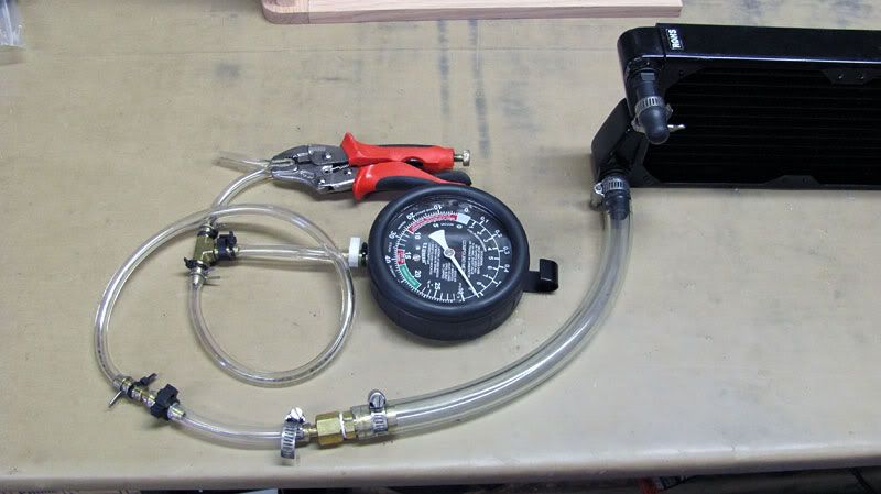
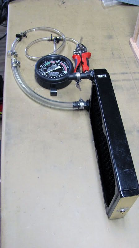
    I am going to leaktest the res with air pressure to make sure everything is tight.
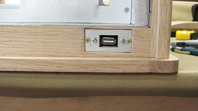
    USB Port

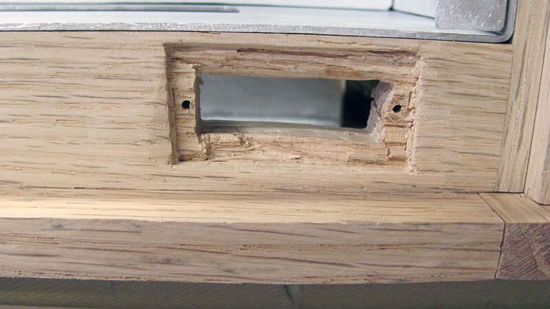
    I use a USB hub for everything, but I do like having at least one port that is plugged directly into the MB. I bought a panel mount USB cable. I made a little rectangular metal mounting piece for the port. I cut out the hole using a jig saw. I then used wood chisels to chisel out the recess for the USB mount.


    I've been pondering whether I'm going to stick with my Aquastream XT, or buy a new MCP35x. The Aquastream is a very quiet pump, which is why I bought it, but the MCP35x is quite a bit smaller, and with the new PWM, the rpm is temp adjustable which should make it very quiet as well. I'm still chewing on this. If I do switch to an MCP35x, I may also make a different res, this time out of some 2” copper tubing (-decisions, decisions...).

    Thanks for stopping by.

  22. #147
    I am Xtreme
    Join Date
    Mar 2007
    Location
    Sugar Land, TX
    Posts
    1,730
    Excellent work as usual! I am stunned every time I check in.

  23. #148
    Xtreme Member
    Join Date
    Nov 2008
    Location
    Eagle Rock, Ca.
    Posts
    398
    You don't want to tighten the clamps like a gorilla
    Had a good hearty giggle at that. heh

    Lots of great information here, Gary.
    Superbly executed!

  24. #149
    I am Xtreme
    Join Date
    Jun 2007
    Location
    Imperial Palace, UDE of Pitatopia
    Posts
    8,396
    I always get a twinge of nervous expectation when I see this thread has new posts.

    Very nice update voigts. Lovin the res.
    Circles SucQ!

    If your annoyed by sigs telling you to put things in your sig, then put this in your sig

    Bribery won't work on me...just say NO to AT!!!

  25. #150
    Xtreme Addict
    Join Date
    Feb 2005
    Location
    Tennessee
    Posts
    1,171
    Quote Originally Posted by theseeker View Post
    Excellent work as usual! I am stunned every time I check in.
    Thanks a lot. I'm trying to keep working on this steadily so that I can hopefully get it done in the not too distant future.

    Quote Originally Posted by CptDreadFlint View Post
    Had a good hearty giggle at that. heh

    Lots of great information here, Gary.
    Superbly executed!
    Thanks again Rick. I thought the gorilla idea would paint a good word picture. Some people think you have to tighten things down to the extreme. Reminds me of those old Samsonite commercials.

    Quote Originally Posted by Waterlogged View Post
    I always get a twinge of nervous expectation when I see this thread has new posts.

    Very nice update voigts. Lovin the res.
    Thanks for your support as always. This was the most complicated res I've done. Having the table saw and aluminum/acrylic blades makes such a huge difference. Its really amazing how getting a few good quality tools makes life so much easier on things like this.

Page 6 of 10 FirstFirst ... 3456789 ... LastLast

Bookmarks

Bookmarks

Posting Permissions

  • You may not post new threads
  • You may not post replies
  • You may not post attachments
  • You may not edit your posts
  •