 |
|
10-30-2007, 04:54 AM
|
#1
|
|
Xtreme Guru
Join Date: Jan 2005
Location: Suomi Finland
Posts: 3,872
|
G92 8800GS/GT/GTS & 9600GSO voltage mods
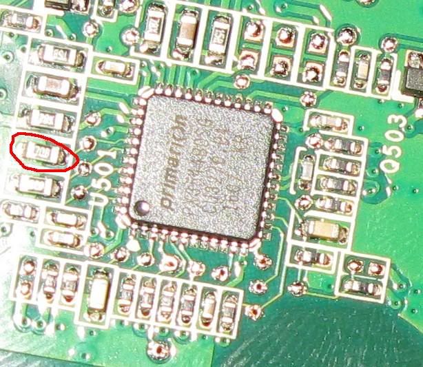
This guide applies only to G92 based nVIDIA 8800GS, GT, GTS and 9600GSO reference boards. If your card has different layout feel free to report here, and, if possible post clear pictures of the card.
http://www.xtremesystems.org/forums/...1&d=1196804211
Higher resolution image @ Imageshack:
Addendum:
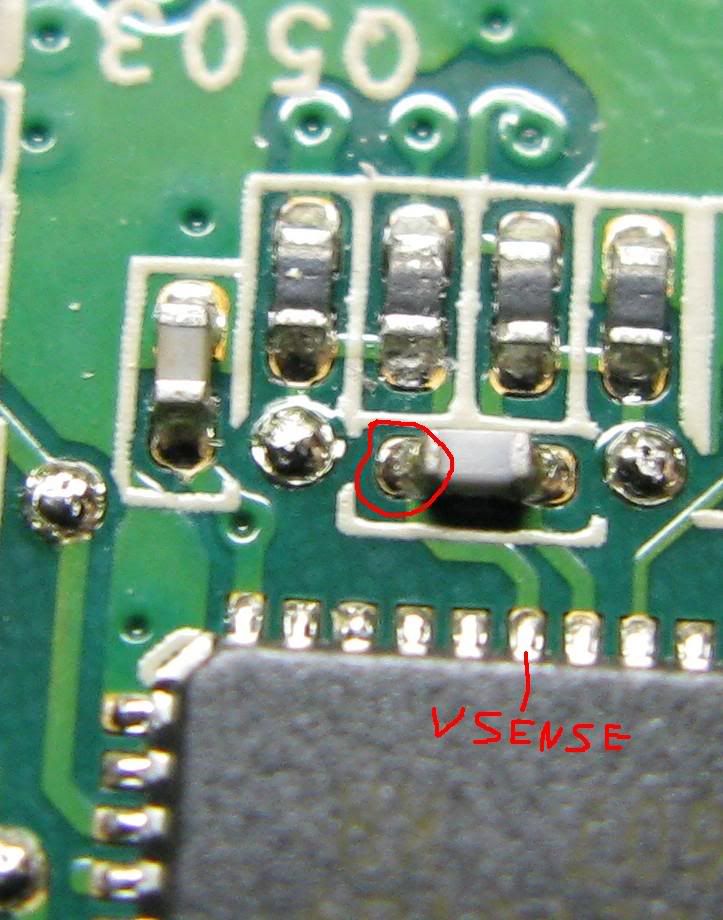
- stock vGPU voltages for this card are 1.05v (2D idle) and 1.15v (3D load)
- stock vMEM voltage for Qimonda GDDR3 (HYB18H512321BF-10) is 2.0v ±5%
- vMEM mod has been deemed almost useless as Qimonda GDDR3 does not OC any better at higher voltages
- 1kΩ variable resistor can be used for the vGPU mod in order to maintain minimum voltage close to stock. 500Ω VR will be more accurate to tune but it will also force vGPU slightly higher than stock even when the VR is tuned for lowest vGPU = maximum resistance.
- vGPU pencil mod turned out to be virtually impossible
- usage of a multimeter is required for tracking the vGPU
- ENJOY!
----
Complete GeForce 8800 GS/GT/GTS Voltmods for reference PCB @ techPowerUp!
__________________
You were not supposed to see this.
Last edited by largon; 08-06-2008 at 10:38 AM.
|
|
|
10-30-2007, 07:11 AM
|
#2
|
|
Xtreme X.I.P.
Join Date: Aug 2004
Location: Chile
Posts: 4,231
|
will help when i get home, i'm looking for a vmod becuase that is the limiting factor on my overclock
__________________
|
|
|
10-30-2007, 07:32 AM
|
#3
|
|
Xtreme Guru
Join Date: Jan 2005
Location: Suomi Finland
Posts: 3,872
|
Btw, here are some easily accessible vGPU measuring points:
__________________
You were not supposed to see this.
|
|
|
10-30-2007, 08:00 AM
|
#4
|
|
Xtreme Enthusiast
Join Date: Mar 2005
Location: Imladris
Posts: 958
|
Pencil mod anyone if it's possible?
__________________
The little air system that could.
|
|
|
10-30-2007, 08:16 AM
|
#5
|
|
Registered User
Join Date: Feb 2007
Posts: 9
|
I can't wait to see this fall out. I'll have one on Thursday, and am anxious to void some warranties with a VF-900.
|
|
|
10-30-2007, 08:38 AM
|
#6
|
|
Xtreme
Join Date: Oct 2004
Location: Banana Republic
Posts: 4,182
|
Quote:
Originally Posted by HousERaT
Pencil mod anyone if it's possible?
|
Only vmem
__________________
...
|
|
|
10-30-2007, 11:26 AM
|
#7
|
|
Xtreme Guru
Join Date: Jan 2005
Location: Suomi Finland
Posts: 3,872
|
Yup, vMEM is definitely pencil modable and actually, vGPU should be too if you're careful [EDIT: VGPU PENCIL MOD UNTESTED! DO NOT APPLY!]). BUT a multimeter is a MUST for a safe vGPU pencil mod... The resistor is awfully tiny but it is doable, it's possible because the affected resistor has higher resistance than on G80GTS/GTX thus pencilling is easier.
The modable resistor for vGPU is the one marked with numbers 2 and 4, but I need measuments of the requested points to be able to calculate the target values for VRs / pencil resistance.
EDIT: VGPU PENCIL MOD UNTESTED! DO NOT APPLY!
For vMEM I need the measurements for spot7-to-spot8/ground in the second pic.
Would someone bother measuring the stock vGPU?
Measuring points can be found in post#3.
__________________
You were not supposed to see this.
Last edited by largon; 11-05-2007 at 01:58 AM.
|
|
|
10-30-2007, 11:51 AM
|
#8
|
|
Xtreme Enthusiast
Join Date: Mar 2005
Location: Imladris
Posts: 958
|
/subscribed
__________________
The little air system that could.
|
|
|
10-30-2007, 02:03 PM
|
#9
|
|
Xtreme X.I.P.
Join Date: Aug 2004
Location: Chile
Posts: 4,231
|
Between 7 & 8 is 612
Between 2 and 4 is 011
Between 2 and ground is 015
1 to 2 = 002
1 to 3 = 002
7 to ground = 002
vGPU 1.06v
__________________
Last edited by metro.cl; 10-30-2007 at 02:23 PM.
|
|
|
10-30-2007, 02:15 PM
|
#10
|
|
...you two characters
Join Date: Mar 2005
Location: Australia
Posts: 15,091
|
here are all the other photos i posted there
here is an actual image of my card here
Quote:
Originally Posted by largon
Thanks, dinos22. 
Need clarification on the existence of certain traces and few resistance measurements, see attachements.
First pic:
There should be traces between points 1, 2 and 3. It certainly does look like there is a trace between 2 and 3, but is there one between 1 and 2? = if there are traces between 1, 2 and 3 then resistance between each is ~4-6Ω.
Also,
Resistance between points 2 and 4? (might be <10Ω)
Second pic:
Resistance between points 5 and 6? (might be around 500Ω)
|
if i set 200 on dial i get 10.4 on points 2 & 4
if i set 20K on dial i get 1.10 on points 5 & 6
looks like my battery might be going on the DMM
best view i can get with camera
naked eye won't work just can't see that   
__________________
Team.AU
Got tube?

Quote:
Originally Posted by Gautam
In the old days, LN2 benching was "cheating". Then LOD was "cheating". And so on and so forth...
|
|
|
|
10-30-2007, 02:27 PM
|
#11
|
|
Xtreme X.I.P.
Join Date: Aug 2004
Location: Chile
Posts: 4,231
|
point 5 & 6? i get similar reading with you Dino just a couple of 0X of diference
__________________
|
|
|
10-30-2007, 02:32 PM
|
#12
|
|
...you two characters
Join Date: Mar 2005
Location: Australia
Posts: 15,091
|
Quote:
Originally Posted by dinos22
if i set 200 on dial i get 10.4 on points 2 & 4
if i set 20K on dial i get 1.10 on points 5 & 6
|
so how do you read this as actual values
can someone tell me
would it be 10.4*200=2080Ω or 2.08kΩ
1.10*20K=22000Ω or 22kΩ
__________________
Team.AU
Got tube?

Quote:
Originally Posted by Gautam
In the old days, LN2 benching was "cheating". Then LOD was "cheating". And so on and so forth...
|
|
|
|
10-30-2007, 02:35 PM
|
#13
|
|
Xtreme Guru
Join Date: Jan 2005
Location: Suomi Finland
Posts: 3,872
|
Thanks metro.cl and dinos22!
Quote:
Between 2 and 4 is 011
Between 2 and ground is 015
|
I'm suprised to hear these points measure that low values. Gonna have to have another look at the vGPU resistor network...
Everything else is like I expected. Especially the vGPU... Lot's of headroom to crank it up, the chip should take 1.4V with ease. :P
Quote:
Originally Posted by metro.cl
point 5 & 6? i get similar reading with you Dino just a couple of 0X of diference
|
Points 5 & 6 were discarded because that particular resistor wasn't in the end that very interesting. 
Quote:
Originally Posted by dinos22
so how do you read this as actual values
can someone tell me
would it be 10.4*200=2080Ω or 2.08kΩ
1.10*20K=22000Ω or 22kΩ
|
10.4 @ 200 dial = 10.4Ω
1.10 @ 20K dial = 1.10kΩ = 1100Ω
The dial selects the maximum measureable resistance. If the result is higher than the selected dial option then the device will simply display "1". So, in a way, one has to know approximately how much the measurement's result should be in order to accurately measure resistance.
Oh, and here is the vMEM mod & vMEM measuring points (stock vMEM is 1.8v ±5%):
__________________
You were not supposed to see this.
Last edited by largon; 10-30-2007 at 02:46 PM.
|
|
|
10-30-2007, 02:44 PM
|
#14
|
|
Xtreme X.I.P.
Join Date: Aug 2004
Location: Chile
Posts: 4,231
|
Quote:
Originally Posted by largon
Thanks metro.cl!
I'm suprised to hear these points measure that low values. Gonna have to have another look at the vGPU resistor network...
Everything else is like I expected. Especially the vGPU... Lot's of headroom to crank it up, the chip should take 1.4V with ease. :P10.4 @ 200 dial = 10.4Ω
1.10 @ 20K dial = 1.10kΩ = 1100Ω
The dial selects the maximum measureable resistance. If the result is higher than the selected dial option then the device will simply display "1". So, in a way, one has to know approximately how much the measurement's result should be in order to accurately measure resistance.
Oh, and here is the vMEM mod & vMEM measuring points (stock vMEM is 1.8v ±5%):
|
any way to pencil mod it? i dont have VR here
__________________
|
|
|
10-30-2007, 02:48 PM
|
#15
|
|
...you two characters
Join Date: Mar 2005
Location: Australia
Posts: 15,091
|
Quote:
Originally Posted by largon
interesting.  10.4 @ 200 dial = 10.4Ω
1.10 @ 20K dial = 1.10kΩ = 1100Ω
The dial selects the maximum measureable resistance. If the result is higher than the selected dial option then the device will simply display "1". So, in a way, one has to know approximately how much the measurement's result should be in order to accurately measure resistance.
|
i get it now thanks buddy
__________________
Team.AU
Got tube?

Quote:
Originally Posted by Gautam
In the old days, LN2 benching was "cheating". Then LOD was "cheating". And so on and so forth...
|
|
|
|
10-30-2007, 02:51 PM
|
#16
|
|
Xtreme Guru
Join Date: Jan 2005
Location: Suomi Finland
Posts: 3,872
|
metro.cl,
Sure, just apply a little pencil over the resistor and measure the resulting resistance & vMEM after every application. I don't know how well Qimonda GDDR3 responds to voltage, so, just to be safe make sure you keep the resistance over 530Ω. This way the vMEM doesn't go above 2.0V
__________________
You were not supposed to see this.
|
|
|
10-30-2007, 03:10 PM
|
#17
|
|
Xtreme Guru
Join Date: Jan 2005
Location: Suomi Finland
Posts: 3,872
|
How about the resistance between these 2 points?
Still about 11Ω?
edit:
It's 00:23 AM over here... And I'm recovering from a nasty flu.
I'm gonna hit the bed.
¦o
__________________
You were not supposed to see this.
Last edited by largon; 10-30-2007 at 03:23 PM.
|
|
|
10-30-2007, 03:41 PM
|
#18
|
|
Xtreme Enthusiast
Join Date: Feb 2005
Location: Belgium
Posts: 844
|
VGPU in BIOS is set to 1,05V. I saw 1,1V is the highest possible value, maybe it works and boosts your overclock 2%
Made modbios via Nibitor, here is the zipfile, use at own risk.
__________________
|
|
|
10-30-2007, 04:44 PM
|
#19
|
|
Xtreme Mentor
Join Date: Jun 2005
Location: Glasgow U.K.
Posts: 3,302
|
The Primarion datasheet is still essentially private
From other cards that use it, does anyone know what pin is the feedback line?
I wanna test the guide on VR-Zone: find feedback pin, measure the resistance between the FB pin and ground. Multiply this value by 20, and get a VR with the resultant value. Solder between FB pin and ground....seems too easy!
There are VMax and Temp-sens pins as well, so might need to find a way of adjusting VID in due time if the limits are too tight
__________________
Proudly using
Crucial Ballistix
Xigmatek air
watercooling by XSPC
Quote:
Originally Posted by T_M
Not sure i totally follow anything you said, but regardless of that you helped me come up with a very good idea....
|
Quote:
Originally Posted by soundood
you sigged that?
why?
|
Last edited by K404; 10-30-2007 at 04:47 PM.
|
|
|
10-30-2007, 05:24 PM
|
#20
|
|
Xtreme Enthusiast
Join Date: Aug 2005
Location: Melbourne, Australia
Posts: 898
|
If someone had a datasheet figuring out an OVP mod wouldnt be too hard... It might even be possible to add the missing phase
edit: Why are the datasheets private anyway? I dont get it
__________________
Q9550 || DFI P45 Jr || 4x 2G generic ram || 4870X2 || Aerocool M40 case || 3TB storage
|
|
|
10-30-2007, 05:33 PM
|
#21
|
|
...you two characters
Join Date: Mar 2005
Location: Australia
Posts: 15,091
|
guys nvidia will not release the info on those
i already tried with all my guys
__________________
Team.AU
Got tube?

Quote:
Originally Posted by Gautam
In the old days, LN2 benching was "cheating". Then LOD was "cheating". And so on and so forth...
|
|
|
|
10-30-2007, 05:37 PM
|
#22
|
|
Xtreme Enthusiast
Join Date: Aug 2005
Location: Melbourne, Australia
Posts: 898
|
I think anyone with a "corporate email account" can get access to the datasheet.. You just have to register here:
http://www.primarion.com/Primarion/RegisterAccount.aspx
(I have no idea what distinguishes corporate email from other email addresses  )
I also found this:
http://www.primarion.com/PrimarionMa...s/PDB-3544.pdf
That should at least give us some clues. Only the pin numbers are missing, but with a bit of tracing it shouldnt be too difficult to find them.
__________________
Q9550 || DFI P45 Jr || 4x 2G generic ram || 4870X2 || Aerocool M40 case || 3TB storage
|
|
|
10-30-2007, 05:52 PM
|
#23
|
|
Xtreme Enthusiast
Join Date: Aug 2005
Location: Melbourne, Australia
Posts: 898
|
Heres an attempt at finding the differences between the working phases and the missing one:
If anyone has a pic to this level of detail of the front of this section i can have a look at it too
edit: From looking at their features list, im not 100% sure its as easy as soldering in the components.
Quote:
-Multiphase power conversion 1-4 phases
-2-bit VID input for additional voltage control
-Driver detect prior to soft-start disables unpopulated phases
-Autonomous or user controlled phase dropping based on current balance and 12V supply faults
|
__________________
Q9550 || DFI P45 Jr || 4x 2G generic ram || 4870X2 || Aerocool M40 case || 3TB storage
Last edited by oohms; 10-30-2007 at 05:57 PM.
|
|
|
10-30-2007, 07:37 PM
|
#24
|
|
Xtreme Enthusiast
Join Date: Aug 2005
Location: Melbourne, Australia
Posts: 898
|
Resistor for OVP mod:
This thread by hipro5 will tell you more:
http://www.xtremesystems.org/forums/...d.php?t=162124
__________________
Q9550 || DFI P45 Jr || 4x 2G generic ram || 4870X2 || Aerocool M40 case || 3TB storage
|
|
|
10-30-2007, 09:13 PM
|
#25
|
|
Xtreme Enthusiast
Join Date: Aug 2005
Location: Melbourne, Australia
Posts: 898
|
MIGHT be the vcore solder point:
(Got info from http://xtreview.com/review164.htm )
Dinos22: What is the resistance between point 1 and ground?
Gawd this is so much more fun than studying for exams
__________________
Q9550 || DFI P45 Jr || 4x 2G generic ram || 4870X2 || Aerocool M40 case || 3TB storage
|
|
|
 |
|
| Thread Tools |
|
|
| Display Modes |
Rate This Thread |
Linear Mode
|
|
Posting Rules
|
You may not post new threads
You may not post replies
You may not post attachments
You may not edit your posts
HTML code is Off
|
|
|
All times are GMT -8. The time now is 01:43 PM.
|