Results 1 to 25 of 1290

Thread: 8800GT voltage mods

Hybrid View

  1. #1
    Xtreme Enthusiast
    Join Date
    Aug 2005
    Location
    Melbourne, Australia
    Posts
    942
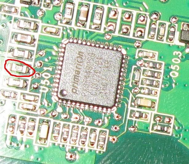
    Resistor for OVP mod:


    This thread by hipro5 will tell you more:
    http://www.xtremesystems.org/forums/...d.php?t=162124
    Q9550 || DFI P45 Jr || 4x 2G generic ram || 4870X2 || Aerocool M40 case || 3TB storage


  2. #2
    Xtreme Enthusiast
    Join Date
    Aug 2005
    Location
    Melbourne, Australia
    Posts
    942
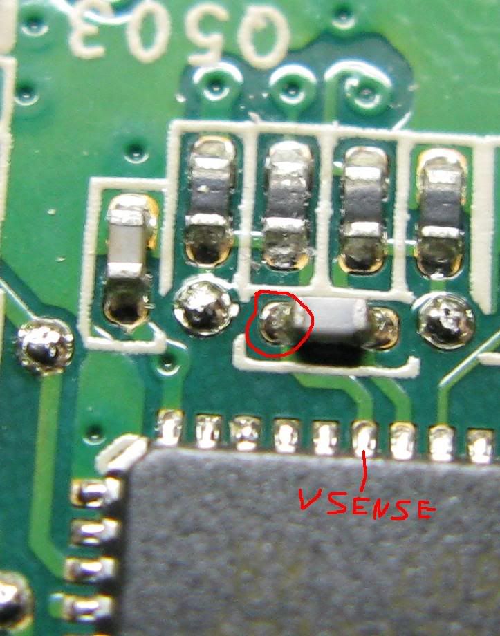
    MIGHT be the vcore solder point:


    (Got info from http://xtreview.com/review164.htm )

    Dinos22: What is the resistance between point 1 and ground?

    Gawd this is so much more fun than studying for exams
    Q9550 || DFI P45 Jr || 4x 2G generic ram || 4870X2 || Aerocool M40 case || 3TB storage


  3. #3
    Xtreme Legend
    Join Date
    Mar 2005
    Location
    Australia
    Posts
    17,242
    Quote Originally Posted by oohms View Post
    MIGHT be the vcore solder point:


    (Got info from http://xtreview.com/review164.htm )

    Dinos22: What is the resistance between point 1 and ground?

    Gawd this is so much more fun than studying for exams
    LOL i know what you mean about taking a break from studying

    i used to go play golf of all things (actually just practice shots myself a looooooong time ago )

    what is point 1 that you refer to
    Team.AU
    Got tube?
    GIGABYTE Australia
    Need a GIGABYTE bios or support?


  4. #4
    Xtreme Enthusiast
    Join Date
    Aug 2005
    Location
    Melbourne, Australia
    Posts
    942
    Quote Originally Posted by dinos22 View Post
    what is point 1 that you refer to
    The circled point in the last pic (connected to vsense)
    Last edited by oohms; 10-30-2007 at 08:26 PM.
    Q9550 || DFI P45 Jr || 4x 2G generic ram || 4870X2 || Aerocool M40 case || 3TB storage


  5. #5
    Xtreme X.I.P.
    Join Date
    Aug 2004
    Location
    Chile
    Posts
    4,151
    Quote Originally Posted by oohms View Post
    The circled point in the last pic (connected to vsense)
    015 from what i get.

    Pin 1 to ground

  6. #6
    Xtreme Guru
    Join Date
    Jan 2005
    Location
    Tre, Suomi Finland
    Posts
    3,858
    Quote Originally Posted by oohms View Post
    MIGHT be the vcore solder point:


    (Got info from http://xtreview.com/review164.htm )

    Dinos22: What is the resistance between point 1 and ground?
    ^This spot-to-GND is essentially the same as spot2/spot3-to-spot4 in this pic:


    I'm pretty sure we're talking about the right soldering spot for the vGPU mod... But here's a safer (it's not a populted SMD solderpad) and much easier soldering point:
    Attached Thumbnails Attached Thumbnails Click image for larger version. 

Name:	G92_vGPU_soldering_point.jpg 
Views:	8076 
Size:	70.2 KB 
ID:	66544  
    Last edited by largon; 10-30-2007 at 11:15 PM.
    You were not supposed to see this.

  7. #7
    Xtreme Guru
    Join Date
    Jan 2005
    Location
    Tre, Suomi Finland
    Posts
    3,858
    11Ω (or 15Ω?) between vSense pin and ground is a horribly low resistance. I was expecting something around 45Ω since G80GTS/GTX which measures to 35Ω output 1.28v, and since the GT has lower vGPU thus the sense resistance should be higher than those on GTS/GTX as all use the same PWM IC. <20Ω is very low and IMO somwhat suspicious...

    If someone is willing to be a guinea pig then I would suggest soldering a 500Ω multiturn VR between this point and ground. Before soldering measure the resistance between soldering points (should be ~15Ω), set VR at max resistance (500Ω), solder the VR, measure resistance between soldering points (should be ~14.5Ω, if much less don't turn the card on) tune down for more vGPU.
    Last edited by largon; 10-30-2007 at 11:17 PM.
    You were not supposed to see this.

  8. #8
    Xtreme X.I.P.
    Join Date
    Aug 2004
    Location
    Chile
    Posts
    4,151
    Quote Originally Posted by largon View Post
    11Ω (or 15Ω?) between vSense pin and ground is a horribly low resistance. I was expecting something around 45Ω since G80GTS/GTX which measures to 35Ω output 1.28v, and since the GT has lower vGPU thus the sense resistance should be higher than those on GTS/GTX as all use the same PWM IC. <20Ω is very low and IMO somwhat suspicious...

    If someone is willing to be a guinea pig then I would suggest soldering a 500Ω multiturn VR between this point and ground. Before soldering measure the resistance between soldering points (should be ~15Ω), set VR at max resistance (500Ω), solder the VR, measure resistance between soldering points (should be ~14.5Ω, if much less don't turn the card on) tune down for more vGPU.
    Damn i found a couple of VR but i think they are not good for the mod i got a 50kΩ and a 10kΩ VR here.

    i'll have to find 500Ω VR but i think it will be hard

  9. #9
    Xtreme X.I.P.
    Join Date
    Aug 2004
    Location
    Chile
    Posts
    4,151
    Quote Originally Posted by largon View Post
    ^This spot-to-GND is essentially the same as spot2-to-spot4 in this pic:


    I'm pretty sure we're talking about the right soldering spot for the vGPU mod... But here's a safer (it's not a populted SMD solderpad) and much easier soldering point:
    that one to ground? what VR value should i get? the space is pretty small and my soldering skills bad but i'll give it a try.

    There is no way for a vGPU pencil mod?

  10. #10
    Xtreme Enthusiast
    Join Date
    Feb 2005
    Location
    Belgium
    Posts
    823
    Quote Originally Posted by cowie View Post
    hows your results?
    Unfortunately this card aint mine, just did a quick research so to please the OC-community. No results, but I can tell you that I could increase to 1,2VGPU. Anyway, XS counts enough people owning such card, it will not take too long before those cards are running at 1GHz I suppose

    Quote Originally Posted by metro.cl View Post
    Sorry to ask but which of both legs is Vsense+? could you upload a picture of the modded card.
    Didn't picture it, you will have to take me on my word here
    Vsen+ is the pin marked below:

  11. #11
    Registered User
    Join Date
    Sep 2007
    Posts
    4
    Hey! Tried the volt-mod on my 8800GT today. But first, could you look at the picture added below; what is that thing? A capacitor?
    Attached Thumbnails Attached Thumbnails Click image for larger version. 

Name:	dfghjk.JPG 
Views:	1414 
Size:	27.0 KB 
ID:	73726  

  12. #12
    Xtreme Guru
    Join Date
    Jan 2005
    Location
    Tre, Suomi Finland
    Posts
    3,858
    2bb1,
    You mean this one? It's a resistor.
    Click image for larger version. 

Name:	resistor.jpg 
Views:	1461 
Size:	67.1 KB 
ID:	73729

    Why?
    You were not supposed to see this.

  13. #13
    Xtreme Enthusiast
    Join Date
    Aug 2005
    Location
    Melbourne, Australia
    Posts
    942
    Hey guys, im going to need some help with this one. Basically i found a number of mosfets on the board whose output voltage i can adjust. But 3 voltages are unknown to me:

    red 1.10v Vcore
    brown 2.00v Vdimm
    yellow 1.79v Tiny mosfet
    blue 5.05v Large mosfet (Looks like 5V supply)
    green 2.44v Large mosfet, near front of card
    gray 1.18v Large mosfet
    Q9550 || DFI P45 Jr || 4x 2G generic ram || 4870X2 || Aerocool M40 case || 3TB storage


  14. #14
    Registered User
    Join Date
    Sep 2007
    Posts
    4
    Quote Originally Posted by largon View Post
    2bb1,
    You mean this one? It's a resistor.
    Click image for larger version. 

Name:	resistor.jpg 
Views:	1461 
Size:	67.1 KB 
ID:	73729

    Why?
    Yes that one!
    It fell off while I were modding. So I "cancelled" the vmod to check if the card were still working; and it does. How can this be if I've removed a resistor? Can it be this way, or should i "mount" it back on?
    Last edited by 2bb1; 03-09-2008 at 04:51 AM.

  15. #15
    Xtreme Enthusiast
    Join Date
    Aug 2005
    Location
    Melbourne, Australia
    Posts
    942
    Ok i found out a few things today.. (went and downloaded the datasheet for the samsung ram it uses)

    - Vdd = Vddq (Damn cheapskates )

    - Vref is controlled by a voltage dividor as such:


    Now im just clarifying, i reduce the resistor between Vref and Vdd to increase Vref right?

    (The only bad thing about this is that each chip has 2 separate Vref points, so 16 modifications in total )

    edit: as it is, that will provide Vref = 51&#37; of Vddq, instead of 70% of Vddq
    Last edited by oohms; 03-11-2008 at 05:57 AM.
    Q9550 || DFI P45 Jr || 4x 2G generic ram || 4870X2 || Aerocool M40 case || 3TB storage


  16. #16
    Xtreme Member
    Join Date
    Aug 2007
    Posts
    370
    Quote Originally Posted by oohms View Post
    Ok i found out a few things today.. (went and downloaded the datasheet for the samsung ram it uses)

    - Vdd = Vddq (Damn cheapskates )

    - Vref is controlled by a voltage dividor as such:


    Now im just clarifying, i reduce the resistor between Vref and Vdd to increase Vref right?

    (The only bad thing about this is that each chip has 2 separate Vref points, so 16 modifications in total )

    edit: as it is, that will provide Vref = 51% of Vddq, instead of 70% of Vddq
    Are you trying to isolate the memory voltage from the memory controller voltage? I was told that wasn't possible, but if you get it working I'm very interested to try it!
    ES Q9550 E0 @ 4.0GHz (471x8.5) 1.256v
    TR-Ultra-120-X, 115CFM 120mm fan
    Maximus II Formula @ 1884MHz FSB
    Ballistix DDR2-800 (4x1GB) 1132MHz 5-5-5-5-15 4-55-8-14-11-3-8-5-4-2T
    eVGA GTX 280 @ 702c/1404s/1260m (1.175v)

    Auzentech XPlosion DTS-Interactive Vantage 'X'-6,727
    300GB Velociraptor, PC P&C 750W
    (3)120mm, (2)90mm, (1)250mm case fans in TT Armor

    27.5" LCD/Z-5500-office, 95" 720P projector/7.1ch-living room
    Logitech Driving Force Pro-Microsim Racing Pod

  17. #17
    Registered User
    Join Date
    Sep 2007
    Posts
    4
    Quote Originally Posted by 2bb1 View Post
    Yes that one!
    It fell off while I were modding. So I "cancelled" the vmod to check if the card were still working; and it does. How can this be if I've removed a resistor? Can it be this way, or should i "mount" it back on?
    Can anyone tell me if it's OK that the resistor is gone?

  18. #18
    Registered User
    Join Date
    Feb 2004
    Location
    Egypt
    Posts
    86
    Quote Originally Posted by 2bb1 View Post
    Can anyone tell me if it's OK that the resistor is gone?
    I think it depends, the card might work fine, but there might be a voltage increase because of removing that resistor, or a decreased functionality that won't appear till you do something specific, or just a general instability!

    You should consider replacing it though. Someone here could give you better advice.
    CPU: Intel Pentium D 925, 3.0GHz @3.82, 40/60c
    RAM: Spectek 2048MB (512x4), DDR2-533 @510, 4-3-3-9-12
    MB: Gigabyte GA-8I945P-G
    GFX: Chaintech 8800GT 600/1500MHz (1.05v) @800/2000 (1.19v), 512MB 900MHz (1.9v), Zalman VF700-Cu, 45/80c
    Monitor: IBM 21" P202 @1600/70Hz
    PSU: Task International 450 Watt, 12v/26A

Tags for this Thread

Bookmarks

Bookmarks

Posting Permissions

  • You may not post new threads
  • You may not post replies
  • You may not post attachments
  • You may not edit your posts
  •