

These numbers are pretty insane. Question though, will it make a real world measurable difference in temps of the components being cooled? Not hating, just curious?Originally Posted by skinnee


These numbers are pretty insane. Question though, will it make a real world measurable difference in temps of the components being cooled? Not hating, just curious?
Corsair 700D
Intel i7 920 @ 4.20|Asus P6T6 Revolution|G.Skill 6gb DDR3 1600|Zotac GTX480|Intel x-25-M 80GB x 2 / Raid0
H2O
|Perfecting the Obsidian series case. Build log to follow soon...|
That is a good question since for the most part the rule of thumb is that flow only helps up to around 1.5Gpm, however what I have been impressed with is how it has helped my flow on my CPU loop, so i am expecting to have some improvement from myCPU loop, but not my GPU loop.
CPUID http://valid.canardpc.com/show_oc.php?id=484051
http://valid.canardpc.com/show_oc.php?id=484051
http://valid.canardpc.com/show_oc.php?id=554982
New DO Stepping http://valid.canardpc.com/show_oc.php?id=555012
4.8Ghz - http://valid.canardpc.com/show_oc.php?id=794165
Desk Build
FX8120 @ 4.6Ghz 24/7 / Asus Crosshair V /HD7970/ 8Gb (4x2Gb) Gskill 2133Mhz / Intel 320 160Gb OS Drive, WD 256GB Game Storage
W/C System
(CPU) Swiftech HD (GPU) EK HD7970 with backplate (RAM) MIPS Ram block (Rad/Pump) 3 x Thermochill 120.3 triple rads and Dual MCP355's with Heatkiller dual top and Cyberdruid Prism res / B*P/Koolance Compression Fittings and Quick Disconnects.
Thanks for taking the time to pass along the info you are gathering. Keeps the community in "Modding Community".
That slight rough spot on the top near the front edge is most likely what is called a sprue (not sure of the spelling) which is a very fine hole or passage in the mold that lets the entrapped air escape when the molten acrylic is driven or injected into the mold via gates on the other end. Normally there are several (I think 2 the top 2 on the bottom and one each side near the T3's face). When the part is popped from the mold the operator uses a sharp knife to free the little bit of plastic that exits the sprue. Short answer is it IS a part of the molding process.
I couldn't reach Brian as it's the weekend, but he did send me a video midweek with a prototype for packaging that has room for a pump. The current packaging does not. As far as I know the ONLY T3's sold with the pump included have been from ModdersMart (a PrimoChill owned estore). I will check with him the next time we talk just to be sure, but I would call the reseller you bought it from as it is likely they bundled your purchase. Also, the chances are it was an employee error or something and not some attempt to mislead you. I don't know which store in the UK you bought it from but the chances are they are like any other store in that they don't want to have unhappy customers...bad for business and all =)
Last edited by BoxGods; 07-18-2009 at 03:45 PM.
It will help in some cases but more importantly your going to see block designers changing gears here pretty fast because they have been designing to the flow rate limits. I already have a cpu block I designed to take advantage of the extra flow installed in my rig for example.
Said another way, good designers work towards the best results they can get within the limitations of the working environment. Now that there is more flow rate available your going to see the more creative companies using it in new designs.
Doesn't seem right, If you have one loop flowing 1.98 and the other flowing 1.49 then it would seem the highest the flow is going to be is 1.98gpm accross that one loop and your average flow through both loops is 1.49 +1.98 / 2 = 1.735 gpm total compared to a single loop @ 1.40gpm there is still a significant gain but adding both loops togethor to get flow rate doesn't seem like the proper methodology to me as the flow should only be = to the least resistance in the loop which would be 1.98gpm shouldn't it?
I am curious what happens if you take the Single loop and put a y after the pump and run parralel lines back into the res divided up exactly the same as the loops using the T3 what happens? Seems that would provide much more accurate analysis as opposed to just comparing single loop with one top to double loop with the other top/res?
Last edited by bluehaze; 07-18-2009 at 04:35 PM.
Flow through the pump = 3.47GPM....that's what he means in both cases when he says "System Flow Rate"
As for averaging the flow as a way to represent what the flowrate is, no need. Showing the flowrate through the two subloops is all that's needed, IMO
One goes up more than 6%, the other goes up more than 41%.
So then if you take the single loop with EK top and split it in two even if it stay at 1.40 gpm for each loop with no gain then all of a sudden the EK top = 2.80 gpm? Doesn't seem right to me for some reason lol
When you split the loop into two subloops, the restriction properties (from the perspective of the pump) change drastically. That, in addition to the D5 being out of the 'fat' part of its efficiency curve, is what allows this design to work so well
And yes, when you go in parallel, the sum of the flowrates of the two subloops/branches/arms/whatever you choose to call them = the flowrate through the pump.
OK it's just confusing because Skinnee is sayin the T3 more than doubles the system flow rater throwing that 123% number out there but in all actuality any pump top with just a y after it would automatically double your system flow rate so it's really not the T3 doubling the flow rate it's just the two loops in parrallel.
I think to gather anything of siginifcance with regards to the T3 you would need to also compare it to the EK top with a Y and parrallel loops as well otherwise the testing methodology is flawed is it not?
I don't think it's flawed at all, he's testing all the product has to offer
The T3 was designed to do exactly this and skinnee is reviewing the product as it was intended to be used. He'll be showing how it performs in a single loop config from both LILO (lower port in, lower port out) and TITO as well as showing some sample configs of when using both sets of ports is beneficial
As for exploring how other pumps perform with a parallel loop config, I'm sure that'll be tested in time.....just a few weeks ago going in parallel was semi-blasphemous (simply because the impact it would have wasn't understood)
That is why I am confused here, I read all the talk of parrellel loops being insignificant and essentially that is all this is, is parallel loops. Initially I was thinking of getting rid of my DDC 3.2 and getting this res and a d5 but in all actuality now I think I would be worse off if I did that.
It just seems confusing as if the T3 is some revolutionary new thing but in all reality the breakthrough here is likely parrallel loops not the T3. Seems like same thing is going to happen if you just have a pump top with two outlets or a pump top with a y on the outlet?
The testing of a single loop vs the dual loop numbers wise is going to favor the dual loop twofold just due to the fact that the dual loop starts with a 100% advantage right off the bat with regards to flow but I'm willing to bet that with regards to temps this won't have any significant difference because your not actually gaining "123%" of flow accross any of the components your trying to cool the difference there is much less.
The numbers certainly look impressive at first glance but once you have a better understanding of it the numbers no longer seem as impressive.
Anyways loking forward to the results, It's all kind of confusing at first but I think I am starting to get the jist of it nowHopefully Skinnee will have temps to go along with his numbers.
Cheers!
I wonder about this too. I hope this review includes the difference in temps vs a single loop or even two separate loops. IMO without this, any review would be incomplete.
Some are missing the distinction Vapor keeps making when he says THROUGH THE PUMP I think. Because water is not compressible in our water cooling operating range just adding a Y 6 inches our so outside of your D5 pump top and one 6" from your inlet will not increase the flow rate through the pump.
I went down that path with the T3's evolution. I started with the standard .30" dia outlet from the D5 into a tank about the same size as the inlet side tank and performance was VERY bad. I reduced the primary outlet tank by 25% and saw some improvement but performance was still bad.
In order to increase flow I increased that primary outlet size that feeds into the expansion chamber and saw another improvement. Obviously if the outlet is bigger the intake needs to be bigger so I tried that which dropped performance to levels lower then we started with. Making the inlet port bigger without a new impeller just kills performance as that ports diameter is matched to the impeller.
Without being able to increase that diameter I was pretty much dead in the water because you can't put out the water faster then you feed it in obviously. It bummed me out because I had determined the correct size for the PEC (pump expansion chamber) and the right ratio between the PEC and the reservoir feeding the inlet side of the pump, but I couldn't alter the diameter of that inlet without a new impeller.
Without boring everyone to death on the subjects of efficiency and viscous boundary layer properties (which to be candid I don't understand well enough to explain) I tried a few different shapes to see if feeding the water into the impeller at different angles helped. It does. Then it was just about matching the outlet diameter to the inlet and sizing the PEC and reservoir tanks.
Vapor has mentioned that he thinks we are now very near the end of what the D5 can do without a new impeller design. I agree with that 100% because the pump side has been customized/improved as much as it can be which is why I focused so much on the inlet side and went with the higher flow rate model of dual loops. Unless we get a new impeller that allows more water in there just is not anymore to be gained with efficiency. I tried a LOT of ratios before getting enough data to hit the sweet spot. When the T3 is knocked off your going to see the same inlet shape, the same area for the outlet, and the same ratio for the PEC because it is optimal. I have found another trick to eek out the last little bit of efficiency on the intake side that is being tested now...beyond that there just isn't much left in the D5 without a new impeller.
EDIT* Just to be clear, to my personal way of thinking, a 1% - 3% increase (and even those are going to be hard to come by now) does not warrant somebody buying a new pump top and is a design failure in my book.
Last edited by BoxGods; 07-18-2009 at 06:08 PM. Reason: spelling and added edit
Then how does 2 loops 1 at 1.90gpm and 1 at 1.48 gpm then = 3.47 gpm? Also was not saying add another Y going into the res, most res on the market have mulitple ports so no Y is neccesary there.
While it is the parallel aspect of the T3 that's the revolution, I'm not quite sure how a regular top + Y-split would fare. The T3 was designed to do parallel while adding a Y-split on another top would be a 'lossy' addition (and a noticeable one at that, I reckon).
I'm very familiar with the numbers the T3 is capable of (been working with skinnee on building an estimator for it) and without giving too much away without his blessing, I'll say what I can about the performance. In a single loop config, its PQ curve is similar to that of the Koolance D5 top. But when 'unleashed' and using both flowpaths (i.e., parallel), the PQ curve is more like the EK's or Detroit Thermo's....and that's not a property of being in parallel, that's just the fact that the top performs better when all ports are used (i.e., as it was intended).
My guess is that a loss similar to the loss that exists when going from LILO+TITO to just LILO or TITO will also exist (though for a different reason) on another top that uses a Y-split.
As for the example that skinnee gave, it's a pretty bad one in the grand scheme of things. Loops that are all-inclusive and have restrictive components will see a big boost from the T3, especially if you isolate the CPU block.
Dual system scenarios also work well
I think i've got it now seeing what Boxgod posted got me thinking, if there is a parallel loop setup where you Y out of the pump then Y back into the res being that water is incompressible you will see no gain. However if you Y out of the pump and your res has dual return ports the res can act as an expansion chamber of sorts. So in effect due to the restriction in the loop the water doesn't need to compress, if you put a Y on the outlet of the pump the water will by nature fill both sides of the Y due to the restriction of each loop and the water taking the least path of resistance.
The least path of restistance will always be the loop that is not full, the problem comes in when you add a Y going back into the res you no longer have any room for expansion therefore you will never see any gain as the volume of water flowing through the 2 loops going back through the Y remains the same because you cannot fit more water through that Y going back into the res.
However if you have two lines going back into the res then you can effectively have 2x the volume of water flowing through the two loops combined when the pressures equalizes and both loops are full.
I can see it in my head but it's really hard to explain what i'm thinking lol not sure if any of this makes sense
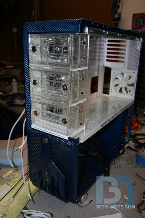
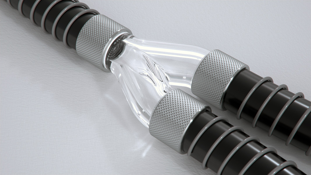
About the new banded bonding method.
Wife had different ideas about me going in to work today to get some video, but I did find some images of them in Boddakers Trident work log that will give you a better idea of what they look like.
The pictures bellow were taken by him and can be found in his work log on several sites.
Hope that helps.
WOOOT! You actually are only slightly off (and I think your only off in explaining it, not in how your seeing it in your head).
A simpler way to visualize what the T3 does differently as compared to simple Y's before and after the pump is just that. The Y method removes the pump so the net effect is no gain whereas the T3 gets its increase THROUGH the pump. Do not view the PEC (the pump expansion chamber located immediately off the D5's main outlet) as separate ports as it is essentially a component OF the pump housing. The twin ports off of the PEC are really now the end of the pump. The same holds true for the reservoir attached to the inlet side of the pump. It's really a part of the pump.
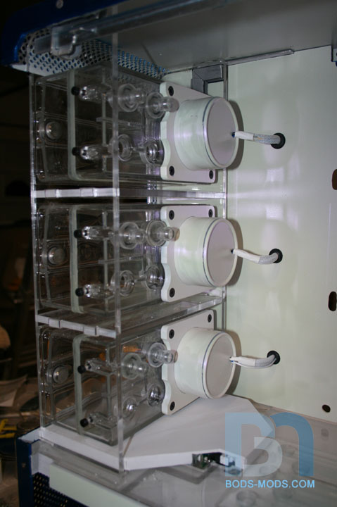
Maybe some images will help:
This shows the inside of the back half. The white cover is over the PEC (pump expansion chamber)
This is the same view with the cover removed and you start to see just how integral the PEC is to pumphead itself.

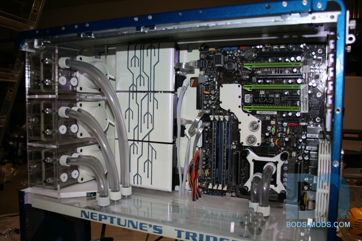
In this image I added a .30" diameter circle to show the size difference between the T3's primary outlet and a normal D5. You can also see the shape of the inlet and how it "humps" to a very sharp edge that is designed to slice the water into the impeller at a radically different angle. I actually thought to try this because of something I read in one of Martin's reviews several years back. Because the inlet diameter is so closely matched to the impeller any changes in its diameter just kills performance.
the next two show the same part from another angle so you can see the relationship of the PEC and the inlet reservoir to each other and the pump head.
I hope that makes the notion of the flow increase coming THROUGH the pump itself clearer.
Last edited by BoxGods; 07-18-2009 at 06:52 PM.
I did my first loop serial going pump---> GPU ---> CPU ----> rad ----> res. After getting my Detroit Thermo top for my D5, I thought that running a parallel run would help CPU out seeing it wouldn't be getting warmed up GPU fluid. So I bought a couple of Bitspower tee's and gave it a shot. I don't have a way of measuring flow, but running some rough temp measurements before and after, temps were the same, peak and idle. It did seem I gained more flow with the top though as there is more movement in my Swifty microres now than there was before. The temp measurements were just taken in AI Suite and EVGA Precision.
Project Millertime: The Core I5 build
Crunching/folding box on air: AMD Athlon X2 7750 Black Edition; Sapphire Radeon HD 4830; Gigabyte MA78GM-US2H; Lian Li PC-V351; Windows 7 RC
BoxGods,
Any idea when they will start shipping with 7/16" 5/8" ghost fittings?
Project Millertime: The Core I5 build
Crunching/folding box on air: AMD Athlon X2 7750 Black Edition; Sapphire Radeon HD 4830; Gigabyte MA78GM-US2H; Lian Li PC-V351; Windows 7 RC
I get what you're saying...but that's not the case.
If you took a loop with a CPU block, a radiator, and other stuff, it would have a pressure drop curve of y= AX^3 + BX^2 + CX + D (well, D=0). If you doubled the components in serial, you would have a pressure drop curve of y= 2AX^3 + 2BX^2 + 2CX + 2D. Basically, you'd double the resistance....
But if you took those same components and split the (doubled up) serial loop into two parallel loops....the overall restriction is much lower than even AX^3 + BX^2 + CX + D (how much so depends on the Y split and all associated with that).
But because the restriction drop is so large from going from the doubled-up serial loop to the parallel loop, flowrate through the pump increases. But overall gains in flow are not necessarily imminent. Going in parallel will only increase the flowrate outside of the parallel'd region (by drastically reducing the restriction the parallel'd components create)....as for what happens within the parallel'd components when using a Y-split, the verdict is still out (there should be some cases where it's still beneficial, but not on the scale of what the T3 does).
The reason why the T3 succeeds at doing this is because while another pumptop would require you to add components (and therefore restriction) in order to go to parallel, the T3 is a native parallel design that requires you to add components (and therefore restriction) to go to serial.
EDIT: BoxGods' PEC explanation is the true way to look at it
I don't agree. OK, maybe a more accurate way to say it, but your very first statement WAY back in this thread is the easiest way to understand it. The difference is WHERE the split (for want of a better term) happens. In the Typhoon III it happens in the pump itself.
is this the GOD of all watercooling? I dont understand you guys are way too technical for me
A long time to never I am afraid. Comes down to cost for the most part. The tooling for the fittings would pay for a nice car. Added to that is the other matched fitting parts that are coming so that there is a FULL line of big radius T's, Y's, Elbow's, flow wheels, Bulkhead pass thru's etc.
The tooling for just one size is I would guess North of 25K

Thanks for the images Boxgods, and thanks for the equations Vapor the images help a bit the equations are all french to me though, no idea WTH any of that means
Anyways I gather what you guys are saying is in order for this to work there needs to be an "expansion chamber" before and after the pump? although that doesn't really make sense to me as it seems as long as there is no restriction at the end of the loops (i.e. both loops going back into a y) but instead the two loops seperately dump back into the res that the two loops would have 2x the capacity of a single loop and therefore the only restriction would be the individual components in each loop. Then due to the resistance of those components in each loop once one loop was full the water would then fill the other loop until some sort of equilibrium was reached.
It seems to me like the restriction on the outlet of the pump wouldn't matter as long as it was less than both of the loops togethor?
Last edited by bluehaze; 07-18-2009 at 07:13 PM.
 Posting Permissions

 is the only emoticon even close to the flow gains over a single serial loop. Geno posted some numbers earlier and I think they may have been scrolled over, let me post this again.
 Reply With Quote
 .
.


Bookmarks