

I have a Gigabyte GA-EP45-DS3R, the vdroop / vdrop is very large, in set bios vcore 1.59375v
idle is 1,508 ~ 1.524v
Full is 1.4720 ~ 1.4400v


I have a Gigabyte GA-EP45-DS3R, the vdroop / vdrop is very large, in set bios vcore 1.59375v
idle is 1,508 ~ 1.524v
Full is 1.4720 ~ 1.4400v
Sorry my bad EnglishLanguage Tools
http://www.google.com.br/language_tools?hl=pt-BR
Q9550 | Gigabyte GA-EP45-UD3P (rev. 1.1) | 4x1GB | SLI 98GTX | LC8850 750w
4685.99 Mhz (H20) - http://valid.canardpc.com/show_oc.php?id=689328
WC - CPU Swiftech Apogee GTZ | Enzotech SNBW | VGA Koolance VID-398 | Rad MagiCool 360ST | Pump DP-1200 | MCRES-Micro Rev2.
Take a detailed pic (macro) of the highlighted area and I'll make you a vDroop mod.

You were not supposed to see this.
ISL6336, from this layout, FB is #16, Vdiff is #17
give a resistor between this 2 pin, you can fix loadline calibration
prepare a 5kohm vr, connect to Pin#16 & Pin#17
using meter to measure it , oringinal should be 45.5k
turn it to 1.5~1.8k, depend on what loading.
sorry don't have camera right now
and my meter is dead.
later i will post it.
Hicookie
Last edited by hicookie; 08-25-2008 at 01:06 AM.
when I am without a camera, tomorrow will take the photo
is that the pencilmod to do?
Sorry my bad English
http://www.google.com.br/language_tools?hl=pt-BR
Q9550 | Gigabyte GA-EP45-UD3P (rev. 1.1) | 4x1GB | SLI 98GTX | LC8850 750w
4685.99 Mhz (H20) - http://valid.canardpc.com/show_oc.php?id=689328
WC - CPU Swiftech Apogee GTZ | Enzotech SNBW | VGA Koolance VID-398 | Rad MagiCool 360ST | Pump DP-1200 | MCRES-Micro Rev2.
Thanks,
I've a large vdroop too (0.6)
waiting for the picture !
Intel Core 2 Quad Q6600 L807A
TRUE-120 / Scythe ULTRA Kaze
Gigabyte EP45-DS3
G.Skill PC2-6400 8GB (4*2GB) PQ
Sapphire HD4870
2* Seagate Barracuda 7200.10 320GB
Samsung EcoGreen F1 1TB
Western Digital Green 1TB
Enermax Noisetaker II 600watts
LG L226WTP-BF 22-Inch
Gigabyte 3D Aurora 570
Apple MacBook MB402LL/A

ihatbs,
You must have meant 0.06v droop as 0.6v would mean the mobo is faulty.
You were not supposed to see this.
Sorry for the picture, is mobile, later made a better

Sorry my bad English
http://www.google.com.br/language_tools?hl=pt-BR
Q9550 | Gigabyte GA-EP45-UD3P (rev. 1.1) | 4x1GB | SLI 98GTX | LC8850 750w
4685.99 Mhz (H20) - http://valid.canardpc.com/show_oc.php?id=689328
WC - CPU Swiftech Apogee GTZ | Enzotech SNBW | VGA Koolance VID-398 | Rad MagiCool 360ST | Pump DP-1200 | MCRES-Micro Rev2.
Sorry my mistake it's around (0.06v), you are rightOriginally Posted by largon


Intel Core 2 Quad Q6600 L807A
TRUE-120 / Scythe ULTRA Kaze
Gigabyte EP45-DS3
G.Skill PC2-6400 8GB (4*2GB) PQ
Sapphire HD4870
2* Seagate Barracuda 7200.10 320GB
Samsung EcoGreen F1 1TB
Western Digital Green 1TB
Enermax Noisetaker II 600watts
LG L226WTP-BF 22-Inch
Gigabyte 3D Aurora 570
Apple MacBook MB402LL/A

Waiting for this one since i'm going to get that mobo too. I've read around the net and i was aware it has a bit of vdroop.
[[Daily R!G]]
Core i7 920 D0 @ 4.0GHz w/ 1.325 vcore.
Rampage II Gene||CM HAF 932||HX850||MSI GTX 660ti PE OC||Corsair H50||G.Skill Phoenix 3 240GB||G.Skill NQ 6x2GB||Samsung 2333SW
flickr
I borrowed my friend's camera and took the picture.
I Felt lazy removing the heatsink and couldn't do better than this one.
Hope it's good enough
EDIT: btw, this is from my EP45-DS3 not the DS3R version but they are both the same except that the southbridge is different.
Last edited by ihatbs; 08-26-2008 at 12:15 AM.
Intel Core 2 Quad Q6600 L807A
TRUE-120 / Scythe ULTRA Kaze
Gigabyte EP45-DS3
G.Skill PC2-6400 8GB (4*2GB) PQ
Sapphire HD4870
2* Seagate Barracuda 7200.10 320GB
Samsung EcoGreen F1 1TB
Western Digital Green 1TB
Enermax Noisetaker II 600watts
LG L226WTP-BF 22-Inch
Gigabyte 3D Aurora 570
Apple MacBook MB402LL/A
the motherboard restarted, and now it's more boot
it turns on or off, On-Off
I tried clear-cmos, remove the battery, exchange CPU, VGA, but nothing happens.
is calling and off, and does not emit any beep
help me
Sorry my bad English
http://www.google.com.br/language_tools?hl=pt-BR
Q9550 | Gigabyte GA-EP45-UD3P (rev. 1.1) | 4x1GB | SLI 98GTX | LC8850 750w
4685.99 Mhz (H20) - http://valid.canardpc.com/show_oc.php?id=689328
WC - CPU Swiftech Apogee GTZ | Enzotech SNBW | VGA Koolance VID-398 | Rad MagiCool 360ST | Pump DP-1200 | MCRES-Micro Rev2.
I too got a bad vdroop can't wait for a mod on this one as it will be first mod I ever had to make but the vdroop is just too bad
Now i'm a bit discouraged on this board, really. I hope largon can give us the fix.
[[Daily R!G]]
Core i7 920 D0 @ 4.0GHz w/ 1.325 vcore.
Rampage II Gene||CM HAF 932||HX850||MSI GTX 660ti PE OC||Corsair H50||G.Skill Phoenix 3 240GB||G.Skill NQ 6x2GB||Samsung 2333SW
flickr
Oh don't do that! So far this board is great! The tech support that you get from the site from LSD is not only the best but all that he says is useful information. He takes the time to help EVERYONE
I'm sticking with the board
Yeah, i know, just can't help thinking that Gigabyte's DS3R series had a noticeable vdroop, specially the first revisions, same for the previous P35 board, quite a vdroop on it. Hell yeah, largon's a master when it comes to voltmodding.
[[Daily R!G]]
Core i7 920 D0 @ 4.0GHz w/ 1.325 vcore.
Rampage II Gene||CM HAF 932||HX850||MSI GTX 660ti PE OC||Corsair H50||G.Skill Phoenix 3 240GB||G.Skill NQ 6x2GB||Samsung 2333SW
flickr
I made a quick mock-up of Hicookie's written guide.
Pins 16 & 17 are marked with red dots but since the pic isn't detailed enough I can't pin point the best soldering points. The legs of ISL6336 might not be too easy to solder on, you'll have to follow the trace that leaves from each pin and find a usable soldering point. Or, you can post a detailed macro pic of the area so I can find & mark actual soldering points.
Thanks.
Last edited by largon; 08-29-2008 at 12:02 AM.
You were not supposed to see this.
Okay now I'm lost I'm guessing this isn't a pencil mod but we must attach the two pins together?
It's a "hard mod", not pencil. For a pencil mod I'd need atleast a macro pic of the area.
You were not supposed to see this.
Where i can get that macro pic?
Intel Core 2 Quad Q6600 L807A
TRUE-120 / Scythe ULTRA Kaze
Gigabyte EP45-DS3
G.Skill PC2-6400 8GB (4*2GB) PQ
Sapphire HD4870
2* Seagate Barracuda 7200.10 320GB
Samsung EcoGreen F1 1TB
Western Digital Green 1TB
Enermax Noisetaker II 600watts
LG L226WTP-BF 22-Inch
Gigabyte 3D Aurora 570
Apple MacBook MB402LL/A
sorry forgot this thread, thanks for shauntx's mention
i take my board back , and done the vmod, you can try pencil or just change the vr.

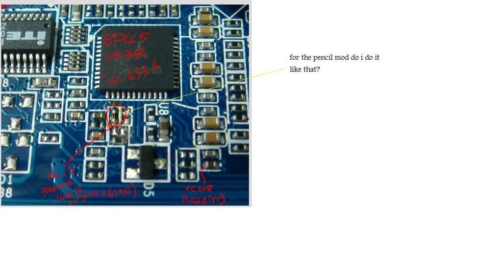
On which do I do the pencil mod? the one that says Vcore reading?
Please tell me for pencil mod if the yellow line in picture is the one that I apply the Pencil mod to?
Also if I want to do the solder mod what size resistor should I use?
Last edited by shauntx; 09-21-2008 at 08:51 PM.
The circled part would be the resistor to pencil.
But it seems the effectiveness of the pencil mod will be non-existant due to the resistance of the part (it's lower than Hicookie reported earlier). One simply can't get from 3.6kΩ down to 146Ω by pencilling. Soldered mod seems like the only way.
You were not supposed to see this.
Okay that sounds about right and I was looking at some other mobo that have had solder mods done however and I think this might be last question k I'm sorry for all of them.
When soldering do I attach 1 10k resistor to each of the points in the picture? and also do I need to ground this solder resistor? Anyone with a picture would be helpful so I know exactly what I'm doing
One single resistor is needed, the principle is the same as for the pencil mod which is you "override" the surface mount resistor with another resistor (doesn't matter whether VR or pencil). You could solder on both ends of the surface mount resistor but I would recommend you find easier 'n' safer soldering points as the tiny resistor can get damaged by heat during soldering. 10kΩ VR could be unconveniently high rated, 1kΩ would work better.
Last edited by largon; 09-22-2008 at 12:38 AM.
You were not supposed to see this.
so use a 1k resistor? I because I have a 10k. Also for the watts to use do I get the 1k resistor with 1/4 watts? also I see they have a 10k-Ohm 15 turn that I can adjust to the same as a 1k is that okay as well its a cermet potentiometer and I can adjust that one and looks easy to use.
Last edited by shauntx; 09-22-2008 at 09:10 AM.
 Posting Permissions


 Reply With Quote

Bookmarks