Page 2 of 3 FirstFirst 123 LastLast
Results 26 to 50 of 69

Thread: My tec liquid chiller project

  1. #26
    Xtreme Member
    Join Date
    Mar 2008
    Location
    Houston TX
    Posts
    349
    Quote Originally Posted by leuler View Post
    I think I can follow any design that you show me.
    OK - here's a simple design, and I'll give you some guidelines to make it work for what you are doing.

    This is a simple fan controller using an 8 pin IC, the MIC520.
    http://www.chipcatalog.com/Micrel/MIC502.htm
    This is a low-frequency (30 Hz as shown) PWM device with the speed set by C1 (100n is .1 uF). You can breadboard this without much trouble. R1 is a 10K thermistor. C2 in the diagram cleans up the 12V so that the IC doesn't see other system noise - it really should go right next to the IC. The IRF530 is a small MOSFET which will do fine on a fan, but to run the TECs you need something bigger. A LOT bigger.

    IR makes a HexFet N-Channel which is rated at 177A at 25C, 125A at 100C. It is in a TO-247AC package which can dissipate 300W. The spec is https://ec.irf.com/v6/en/US/adirect/...uctID=IRFP2907

    Put that on a good sized heat sink (or strap it to your hpt side plate somewhere) in place of the IRF530 and you are basically there.

    The last step is to improve the low pass filtering. Almost any old power supply has a big toroidal choke or two. They are just some big wire wrapped around a ferrite donut and are usually an inch or two in size. You don't want the ones with lots of different windings - just a simple single layer of 12GA wire or something like that. Almost any size will do. Usually the big power toroid has two windings, each going halfway around the donut. Just use one side.

    That toroid is being used as an inductor, and goes between the high side of Q1 and the load. On the other side of the choke, you want a big cap tied to ground, basically putting the + lead on the - fan in the drawing. This will produce a second order filter. The values are not critical, especially since we probably have no idea what the toroid impedance is.

    A 4700 uF 35V cap should do the job (Radio Shack about $6) - but if there is significant AC on the output when you test it, just go to a bigger cap or add more in parallel.

    With an inductor, you also need to 'snub' transients. Put a 6A 50V diode ($2 at Radio shack I think) between ground and the high side of the MOSFET, with the 'line' on the diode attached to the high side. That will keep the inductor from blowing up your MOSFET.

    The system turns full on for 2 seconds at power-up, then adjusts to the thermistor value. You adjust VR1 to set the desired level for a given temperature of thermistor R1. With the component values shown (thermistor with 10K at 25C), and VR1 at the bottom of the range, the circuit will be off at 25C, and all the way at the top, it will be 100% power at 25C. The 'off' level is .4 of the supply, and 100% is .7 of supply.

    But you probably don't want a 25C design center. You want a thermistor with 10K resistance at 0C. At that temperature, a Sensor Scientific KW302C thermistor has 10K resistance. Let's say you want to maintain water at 1C. You adjust VR1 to get whatever level of power gets you to 1C, at the load you care about.

    So lets assume that your load is 300W, and you are willing to wait 10 minutes or so to let things stabilize, tweaking the control a bit. You will probably end up with about 7V on the TECs to get that cooling, based on our other assumptions, which puts VR1 near the middle of its range - 20K below, 15K above. That's just a guess, but OK for this example.

    If for whatever reason the cold side starts to rise, R1 value will start to decrease, and more juice will go to the TECs.

    The 'slope' of the thermistor determines the sensitivity to temperature change. R1 is a negative temperature coefficient (NTC) thermistor. So when temp gets to 5C, it has 8.4K resistance. That takes the TECs to 8V. At 10C, they are at 9.2V, 15C at 10.5V, and at 20C you are at the full 12V.

    Clearly, the performance of your setup and the load also determine the way this works. If your cooling is better than we think, then all the currents will be lower. But let's see what happens if the load goes down - your hard calculation ends and the load drops to 140W.

    Now the temp will start to drop in the cold loop. at -5C, you are at 4V. But you will never get there, because the TEC dT combined with even a modest drop in voltage will drop the cooling power to 140W with a shift of even a few degrees.

    With this setup, and your current TECs, you would use only about 250W to maintain 0C with a 300W load. If you set the target at 5C or so, you would use less than 200W to do it. And if you go out of OC mode and back to normal, the TECs will drop to almost nothing - maybe 100W in to cool 140W. So you could run the setup 24x7 and it would adjust itself to your cooling needs without any changes.

    If the system has been off for a while, and everything is at room temp, the TECs will go full on and stay there for a while. But even with a 300W load, you are pulling .5C per second out at full power, so in a minute or two, they will start to power back, and you should stabilize in 5 minutes or less at your target temperature.
    Attached Thumbnails Attached Thumbnails Click image for larger version. 

Name:	my502.gif 
Views:	2263 
Size:	4.8 KB 
ID:	79401  
    Last edited by Uncle Jimbo; 05-27-2008 at 01:20 AM.

  2. #27
    Xtreme Member
    Join Date
    Mar 2008
    Location
    Houston TX
    Posts
    349
    Quote Originally Posted by leuler View Post
    According to Swiftech's site, if I manage to get the coolant on the coldside
    to be 0 deg C and I use an Apogee GTX ( currently the best block I own )
    on my QX6700 and the load is 300 watts, the CPU temp will be around
    30 deg C. Not what I am hoping for.

    But, the cpu may get to higher speeds at lower voltage with lower temps.
    So, I might get the QX6700 a fair amount over 4GHz without approaching
    300 watts.

    Still, I'll need a block that is better than .1 C/w to get below ambient
    at highest loads.
    You have plenty of cooling power. You could go sub-zero on the cold side. A really good block at 2.5 GPM can do .06 or better. Going to -10C would get your CPU down around 8C with that combo.

    Or you could continue in crazy Xtreme and put a 437 TEC between the CPU and the block. That kind of defeats the efficiency of the rest of your design, since everything would be full bore all the time, but you could drop 10C or so more. Not recommended

  3. #28
    Xtreme Addict
    Join Date
    Jan 2007
    Location
    Michigan
    Posts
    1,785
    This is an awesome setup and great work! I just keep wondering what will be done about condensation? Seems like if you're running 0c liquid through that cpu block there will be plenty of condensate all over the place. How are you getting around this small problem design wise?
    Current: AMD Threadripper 1950X @ 4.2GHz / EK Supremacy/ 360 EK Rad, EK-DBAY D5 PWM, 32GB G.Skill 3000MHz DDR4, AMD Vega 64 Wave, Samsung nVME SSDs
    Prior Build: Core i7 7700K @ 4.9GHz / Apogee XT/120.2 Magicool rad, 16GB G.Skill 3000MHz DDR4, AMD Saphire rx580 8GB, Samsung 850 Pro SSD

    Intel 4.5GHz LinX Stable Club

    Crunch with us, the XS WCG team

  4. #29
    Xtreme Member
    Join Date
    Mar 2008
    Location
    Houston TX
    Posts
    349
    Quote Originally Posted by Vinas View Post
    This is an awesome setup and great work! I just keep wondering what will be done about condensation? Seems like if you're running 0c liquid through that cpu block there will be plenty of condensate all over the place. How are you getting around this small problem design wise?
    Vinas - for sure, for any of the temps we have been talking about, Leuler will need to do the whole seal it up thing. Insulating the tubing to the block will be a must also. When he gets that far we can point to the good references on this forum and elsewhere... Keeping the coolant from freezing is another thing to think about if he really wants those temps at the CPU.

  5. #30
    Registered User
    Join Date
    Apr 2008
    Posts
    85
    Quote Originally Posted by Uncle Jimbo View Post
    You have plenty of cooling power. You could go sub-zero on the cold side. A really good block at 2.5 GPM can do .06 or better. Going to -10C would get your CPU down around 8C with that combo.

    Or you could continue in crazy Xtreme and put a 437 TEC between the CPU and the block. That kind of defeats the efficiency of the rest of your design, since everything would be full bore all the time, but you could drop 10C or so more. Not recommended
    The whole project seems crazy Xtreme to everybody already

    I don't think a 437 TEC would add much to an overclock attempt. I've read
    about people using LN on QX6700s and not getting more than 4.5 to 4.7 GHz.

    I do have to admit that I started thinking about a chiller when I was trying
    to figure out a way to keep the hotside of a big TEC cool. But it is not worth
    adding a big TEC at the cpu, power consumption wise. I wouldn't even get
    the pleasure of seeing how fast I could make my house meter turn - the
    power company changed it to a digital meter last year.

  6. #31
    Registered User
    Join Date
    Apr 2008
    Posts
    85
    Quote Originally Posted by Vinas View Post
    This is an awesome setup and great work! I just keep wondering what will be done about condensation? Seems like if you're running 0c liquid through that cpu block there will be plenty of condensate all over the place. How are you getting around this small problem design wise?
    Thank you Vinas. I'm going to treat this like it is a phase change set up.
    Everything on the coldside loop will be insulated, including the water block
    and cpu, as well as using dielectric grease in the socket and some conformal
    spray on the motherboard. Besides protecting against condensation, it will
    help against losing cooling power to the air.

  7. #32
    Xtreme Member
    Join Date
    May 2008
    Posts
    416
    It should be a fancy idea to use Cascade TECs:

    CPU Surface>WATER LOOP>(Coldest Side)TEC-80Watts>TEC-160Watts(Hottest Side)>WATER+TEC Cooler

    CPU Surface>WATER LOOP>(Coldest Side)TEC-80Watts>TEC-160Watts(Hottest Side)>Fan+TEC Cooler

    Anyway it's not easy to have some subzero stuff with TECs


    Intel DP55KG-Core i5-750-Kingston Hyperx DDR3 1800MHz-EVGA 9800GX2SC-High Power HPC 1000 G14C 1000W-HP W2448HC HDMI
    Intel DP55KG-Core i5-750-Kingston Hyperx DDR3 1800MHz-Sparkle 8800GTX-SilverStone ST1000NV 1000W-Samsung T260HD

  8. #33
    Registered User
    Join Date
    Apr 2008
    Posts
    85
    Thank you for the design Uncle Jimbo

    I do understand how it functions.

    I'm thinking about making a test run with the chiller this Saturday, provided
    that I have the time. I need to see if it will work as well as we have
    speculated. If not, then the primary culprit would probably be my application
    of the Arctic Ceramique and I will have to unbolt the chiller and reapply.

    If the chiller does live up to expectations, then combining it with the
    power controller would make it into somewhat of a Coolit system on
    steriods. That would exceed my expectations for this project.

  9. #34
    Xtreme Member
    Join Date
    May 2008
    Posts
    416


    Intel DP55KG-Core i5-750-Kingston Hyperx DDR3 1800MHz-EVGA 9800GX2SC-High Power HPC 1000 G14C 1000W-HP W2448HC HDMI
    Intel DP55KG-Core i5-750-Kingston Hyperx DDR3 1800MHz-Sparkle 8800GTX-SilverStone ST1000NV 1000W-Samsung T260HD

  10. #35
    Xtreme Member
    Join Date
    Nov 2005
    Posts
    309
    I think I worked out some numbers for all sorts of combinations of stacking/cascading peltiers. You would only ever do it to achieve higher dT than a single layer can provide.

    I'm pretty sure you are always better off just raising the voltage of a single layer towards its maximum to achieve the higher dT. Only once you reach this maximum should you try more than one layer (I can't see why it would ever be worth it for our applications).

    Edit: On second thoughts maybe there are situations where this is viable (just not how I'd use them). I'll get back on this tomorrow with an example if I can think of one.
    Last edited by Scarlet Infidel; 05-29-2008 at 02:54 PM.

  11. #36
    Registered User
    Join Date
    Apr 2008
    Posts
    85
    Quote Originally Posted by Scarlet Infidel View Post
    I think I worked out some numbers for all sorts of combinations of stacking/cascading peltiers. You would only ever do it to achieve higher dT than a single layer can provide.

    I'm pretty sure you are always better off just raising the voltage of a single layer towards its maximum to achieve the higher dT. Only once you reach this maximum should you try more than one layer (I can't see why it would ever be worth it for our applications).

    Edit: On second thoughts maybe there are situations where this is viable (just not how I'd use them). I'll get back on this tomorrow with an example if I can think of one.
    Cascades or multistage peltiers are used in situations where precisely
    controlled low temperatures are needed and the heat load is low. Situations
    that call for temperatures lower than a single peltier can achieve.
    One situation I can think of is the use of a photomultplier, which can
    detect a low flux of photons. I know that it is used in physics and astronomy.
    It needs to be kept very cool because thermal noise can be misinterpreted
    as a photon striking the sensor ( the speckles you see when using a digital
    camera in very low light situations is caused by thermal noise ). Also,
    cascades are used when cooling small samples ( biology, chemistry,etc)
    to, let's say, -30 to -50 deg C.

    For PCs, I can't think of a low heat producing part that needs to be cooled
    to that low of a temp.

  12. #37
    Xtreme Member
    Join Date
    Mar 2008
    Location
    Houston TX
    Posts
    349
    Quote Originally Posted by Scarlet Infidel View Post
    I think I worked out some numbers for all sorts of combinations of stacking/cascading peltiers. You would only ever do it to achieve higher dT than a single layer can provide.

    I'm pretty sure you are always better off just raising the voltage of a single layer towards its maximum to achieve the higher dT. Only once you reach this maximum should you try more than one layer (I can't see why it would ever be worth it for our applications).

    Edit: On second thoughts maybe there are situations where this is viable (just not how I'd use them). I'll get back on this tomorrow with an example if I can think of one.
    As you say, it's done for very small TECs to create big dT - usually for instrument control. The problem with moving any power is that the second TEC in the stack is at a bad operating point because it has to move the heat load of the first, so the CoP of the whole stack is not good. But done carefully it can have some benefits.

    Let's say you want to move 20W heat load and have the cold side at -50C in a 25C ambient. No TEC in the world will do that in one stage. so for the first stage, target a 40C dT, and we need to have Th at -10C. Max CoP on the 40C CoP curve is .25 or so at .625 of Imax, and pretty flat through 80% Imax. Using a 12715, we need 10A to move 20W at that Th. The 12715 needs 9V to get there, so total power on the hot side is 90W power in + 20W load heat for a total of 110W. If we put a 19933 on top of that, we need to move that load heat plus whatever power we put in. If we assume enough cooling to keep the hot side at 30C, then we are at the 50% Imax point, 16.5A at 12V for power in of 200W and total heat load of 310W.

    That's obviously not real efficient, but if what you want is a -50C cold side, and don't need to move a lot of heat, that would get you there.
    Last edited by Uncle Jimbo; 05-29-2008 at 07:47 PM.

  13. #38
    Xtreme Member
    Join Date
    Mar 2008
    Location
    Houston TX
    Posts
    349

    Three stage TECs

    There are a number of three stage modules for precise temperature control at low temperatures, but they don't move much power. One I saw had power control of each stage to maintain the interface temp, and could control the load temp to .1C at -80C from 25C ambient. But the heat moved was less than a watt for 300W in.
    Last edited by Uncle Jimbo; 05-29-2008 at 07:56 PM.

  14. #39
    Xtreme Member
    Join Date
    Nov 2005
    Posts
    309
    Yeah, I know those kinds of uses, my dad uses multistage peltiers for cooling CCD chips (low heat output and require very low temperatures).

    I think we could find some uses for this in PC cooling, I'd give an example but I find the calculations with existing software to be a complete pain. I could do it on my software in seconds, but then my software doesn't give the right numbers yet.

  15. #40
    Registered User
    Join Date
    Apr 2008
    Posts
    85
    I tried out the chiller over the weekend. I'll try tonight to post some pics
    and go into some detail, but for now I'll just give some numbers.


    20 watt load ( pump only )

    Ambient - approx 29 deg C
    Hotside Loop - approx 35 deg C
    Cold side Loop - approx - 6.5 deg C

    85 watt load ( pump and E8400 at stock and full load)

    Ambient - approx 29 deg C
    Hotside Loop - approx 35 deg C
    Coldside Loop - approx -3 deg C

    140 watt load ( pump and E8400 at 4.0 GHz and 1.35 V )

    Ambient - approx 29 deg C
    Hotside Loop - approx 35 degree C
    Coldside Loop - approx -1.5 degree C

    These numbers are from memory and are not quite right but not to far off.
    Anyway, the Air/Hotside delta stayed at about 6 deg C.

    More later.

  16. #41
    Registered User
    Join Date
    Apr 2008
    Posts
    85
    I used a Gigabyte DS3 motherboard and E8400 processor for the testing.
    My DFI motherboard isn't working, and the Gigabyte motherboard can't
    handle the load of a quad at high frequencies. I used Prime95 version 25.5
    running small FFTs for an hour for each set of temperatures.


    With no load except for the heat dump from the pump ( approx 20 watts ),
    I got these temps:

    AMBIENT (29.4 deg C)


    HOTSIDE WATER (34.6 deg C)


    COLDSIDE WATER (-6.4 deg C)


    Then I tried it out with the E8400 at 1.15 volts and 3.0 GHz. I can't find
    a consensus on the heat produced by the processor. I've seen a range
    of 30 to 65 watts. So, the total heat load at these settings ( counting
    pump) is 50 to 85 watts.

    AMBIENT (29.5 deg C)


    HOTSIDE WATER (35.2 deg C)


    COLDSIDE WATER (-4.7 deg C)


    Next, I overclocked to 4.0 GHz and 1.35 volts ( 100 to 140 watts load)


    AMBIENT (30.6 deg C)


    HOTSIDE WATER (35.9 deg C)


    COLDSIDE WATER (-1.6 deg C)


    I ran one more test this afternoon ( no pics for this one). I'm unfamiliar
    with the Gigabyte motherboard, so the highest overclock I've gotten
    so far is 4.32 GHz at 1.45 volts. It was prime stable for 7 minutes, and these
    are the temps I recorded:

    Load - 140 to 160 watts
    Ambient - 31.7 deg C
    Hotside - 37.4 deg C
    Coldside - 0.9 deg C

    I tried to use RealTemp and CoreTemp to record the CPU temp, but
    neither program could read the temp at 3.0 GHz ( the temp would not change
    between idle and full load ), and I don't trust what they reported at
    4.0 GHz. At 4.32 GHz, CoreTemp showed 32 C and 27 C, and RealTemp
    showed 23 C and 17 C ( the waterblock mount is definitely not good,
    but that doesn't matter at this time - this is a temporary set up).

  17. #42
    Xtreme Member
    Join Date
    May 2006
    Posts
    187
    Aren't you worried that the shelf you have that set up on is too wimpy?

    Those temps look good!
    Play-toy Rig: QX9650/Maximus Formula/Mushkin Redlines 2x1GB/3870X2 + 3870/Raptor-X/Zalman HP-1000/XP Pro-32 and Vista 64/3x12 Rad + EK-Supreme + Swiftech MCP-655 on the CPU/3x12 Rad + EK block + Koolance RP-1000 on the 3870X2/2x12 Rad + Koolance full block + Koolance RP-1000 on the 3870/1x12 rad + EK blocks + Koolance RP-1000 on the NB/SB/VRMs/Modded Lian Li Cube/SilenX fans.

    Image processing rig: Q6700/Blitz Formula SE/Mushkin DDR2-8500/HIS 3870/Raptor-X/Mushkin 800 watt PS/ Thermalright IFX-14/Armor w/ 25cm door fan.

  18. #43
    Xtreme Member
    Join Date
    Mar 2008
    Location
    Houston TX
    Posts
    349
    Those are some nice temps. It looks like you have an effective Rt of .06 or better which is pretty good all by itself - except you also have a -40C dT from ambient in the mix. Really nice work.

    I don't know if you saw this slightly cleaner write-up of the pwm controller -

    Click image for larger version. 

Name:	PWM-TEC-Controller_web.gif 
Views:	2545 
Size:	14.8 KB 
ID:	80058

    what voltage were you running on your TECs?
    Last edited by Uncle Jimbo; 06-09-2008 at 11:34 PM.

  19. #44
    Xtreme Member
    Join Date
    Mar 2008
    Location
    Houston TX
    Posts
    349
    Quote Originally Posted by leuler View Post
    Thank you for the design Uncle Jimbo

    If the chiller does live up to expectations, then combining it with the
    power controller would make it into somewhat of a Coolit system on
    steriods. That would exceed my expectations for this project.
    The TC648VPA from Microchip Technology is almost identical to the MIC502, except it is a 5V max Vdd and has slightly different cap values (also the second input on pin 5 is not there). It is a little cheaper than the MIC502. C1 is a 1uF for 30Hz, Z1 is 4.7V, R1 is 680 Ohm. If anyone is interested I could do some testing and give actual circuit values.

    Also someone suggested that with either IC, use a .1 uF from pin 1 to ground, to dampen any noise - in some cases people have heard humming or other audible noise without that cap.

    Both parts are available in the US at http://www.cavalierstock.com - other places too I'm sure.

  20. #45
    Xtreme Addict
    Join Date
    Jan 2007
    Location
    Michigan
    Posts
    1,785
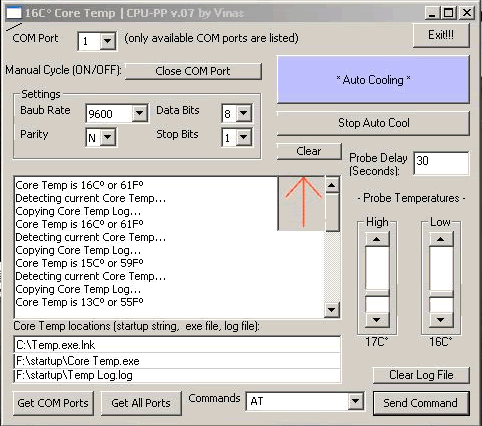
    I'm worried about the condensation on the CPU block because it doesn't look insulated... If the board isn't prepared for sub ambient temps I am afraid you'll find water in the CPU socket, or worse just a bunch of corrosion on the CPU pins resulting in a dead board. My last chill water setup had the later, unfortunately. I had insulation on the CPU block but no dielectric grease in the socket -- I learned the hard way. =\ After that setup I made a program to throttle the temp to 18C by controlling the COM port. Just a simple relay off the COM port to turn on 120vac to the compressor. My program would read the coretemp log and turn on or off the temp according to that. Fun stuff.


    I'm excited about this rig so please don't think I'm trying to be pessimistic -- just excited to see it work well for you! Thanks for sharing the pictures, post more soon! =)
    Current: AMD Threadripper 1950X @ 4.2GHz / EK Supremacy/ 360 EK Rad, EK-DBAY D5 PWM, 32GB G.Skill 3000MHz DDR4, AMD Vega 64 Wave, Samsung nVME SSDs
    Prior Build: Core i7 7700K @ 4.9GHz / Apogee XT/120.2 Magicool rad, 16GB G.Skill 3000MHz DDR4, AMD Saphire rx580 8GB, Samsung 850 Pro SSD

    Intel 4.5GHz LinX Stable Club

    Crunch with us, the XS WCG team

  21. #46
    Registered User
    Join Date
    Apr 2008
    Posts
    85
    Quote Originally Posted by Clue69Less View Post
    Aren't you worried that the shelf you have that set up on is too wimpy?

    Those temps look good!
    Heck No!!! There's too much crap underneath the shelf for it to collapse

    I have to do all my work on the chiller at my warehouse because the room
    that I would use at my house is being used as an extra large closet at the
    moment

    I am pretty happy with the temps, and I think they can be made a touch
    better.

  22. #47
    Registered User
    Join Date
    Oct 2003
    Posts
    75
    Quote Originally Posted by leuler View Post
    I tried to use RealTemp and CoreTemp to record the CPU temp, but
    neither program could read the temp at 3.0 GHz ( the temp would not change
    between idle and full load ), and I don't trust what they reported at
    4.0 GHz. At 4.32 GHz, CoreTemp showed 32 C and 27 C, and RealTemp
    showed 23 C and 17 C ( the waterblock mount is definitely not good,
    but that doesn't matter at this time - this is a temporary set up).
    Have you tried Smart Guardian for CPU temperature? It was the only program I found that showed a difference between idle and load temps for the e8400 below freezing. CPU temps need to be converted from 255C = -1C, 254C = -2C and so on. Also, you might need to adjust the cpu temp in the BIOS.


    In any case, great water temps! I look forward to seeing the permanent setup.
    .

  23. #48
    Registered User
    Join Date
    Apr 2008
    Posts
    85
    Quote Originally Posted by Uncle Jimbo View Post
    Those are some nice temps. It looks like you have an effective Rt of .06 or better which is pretty good all by itself - except you also have a -40C dT from ambient in the mix. Really nice work.

    I don't know if you saw this slightly cleaner write-up of the pwm controller -


    what voltage were you running on your TECs?

    I did see a revised drawing, but the added notes on the drawing are a
    welcomed addition.

    I am ashamed to admit, though I had access to at least a half a dozen
    multimeters, I forgot to use one to see how much voltage the server PSUs
    were actually putting out. I was using the 12 volt rails.

  24. #49
    Registered User
    Join Date
    Apr 2008
    Posts
    85
    Quote Originally Posted by Vinas View Post
    I'm worried about the condensation on the CPU block because it doesn't look insulated... If the board isn't prepared for sub ambient temps I am afraid you'll find water in the CPU socket, or worse just a bunch of corrosion on the CPU pins resulting in a dead board. My last chill water setup had the later, unfortunately. I had insulation on the CPU block but no dielectric grease in the socket -- I learned the hard way. =\ After that setup I made a program to throttle the temp to 18C by controlling the COM port. Just a simple relay off the COM port to turn on 120vac to the compressor. My program would read the coretemp log and turn on or off the temp according to that. Fun stuff.


    I'm excited about this rig so please don't think I'm trying to be pessimistic -- just excited to see it work well for you! Thanks for sharing the pictures, post more soon! =)
    It is insulated better than it appears in the picture, and I did use dielectric
    grease in the socket. I was careful and actually over did it with the RTV -
    all because I wasn't careful enough when I first set this up and killed my
    primary board . I hadn't had much time to work on my set up the
    previous two weeks and I was eager to test how well the chiller would
    work. So, one afternoon I got back a little early to the shop and rushed
    to get the water block mounted and insulated so that I could do my testing
    last Saturday. Big mistake. I didn't get it completely sealed. To compound
    things, I let the chiller run for a while without starting up the computer and
    didn't check the motherboard over before starting up. Needless to say,
    it wouldn't boot I don't think water got into the socket. Instead,
    I believe water got into circuitry around the northbridge. Hard lessons
    are usually the most effective lessons.

    Anyway, this is a temporary set up. I'm going to break it back down,
    tweak it a little, build Uncle Jimbo's controller, shoehorn all the compenents
    into a case I'm going to build, and most importantly, properly insulate
    the coldside loop.

    By the way, I like your way of controlling your temps. Chillers should be
    a versatile cooling method. Keep the temps around ambient for normal use,
    and extra cooling power when you want to go for extra speed.

  25. #50
    Registered User
    Join Date
    Apr 2008
    Posts
    85
    Quote Originally Posted by scifikg View Post
    Have you tried Smart Guardian for CPU temperature? It was the only program I found that showed a difference between idle and load temps for the e8400 below freezing. CPU temps need to be converted from 255C = -1C, 254C = -2C and so on. Also, you might need to adjust the cpu temp in the BIOS.


    In any case, great water temps! I look forward to seeing the permanent setup.
    I actually have Smart Guardian, and I did use it. It wasn't reading the
    Gigabyte motherboard correctly - the voltage readings were way off and
    the CPU temp was being reported as the PWM temp. However, I did forget
    that the temps have to be converted when they are below 0C. The board
    came with EasyPro 5, which also reports -1C as 255C and so on.

Page 2 of 3 FirstFirst 123 LastLast

Bookmarks

Bookmarks

Posting Permissions

  • You may not post new threads
  • You may not post replies
  • You may not post attachments
  • You may not edit your posts
  •