Results 1 to 25 of 52

Thread: Pros and Cons of Digital PWM?

Threaded View

  1. #16
    k|ngp|n/Sham my brothers
    Join Date
    Aug 2002
    Location
    Athens---Hellas
    Posts
    5,693
    Quote Originally Posted by OSKAR_WU View Post
    When the cpu load changes , no matter how fast the VRM can respond , there is always a very short period you need to use the Choke and Capacitor to maintain the voltage stable ... If we can design unlimited capacitor on the board , we can remove the droop design when the capacitor can handle all these transient state , but that's not possible ...
    From the schematics you have uploaded, users can see how the power circuit responds from heavy load to light load (idle) and visa-versa.....

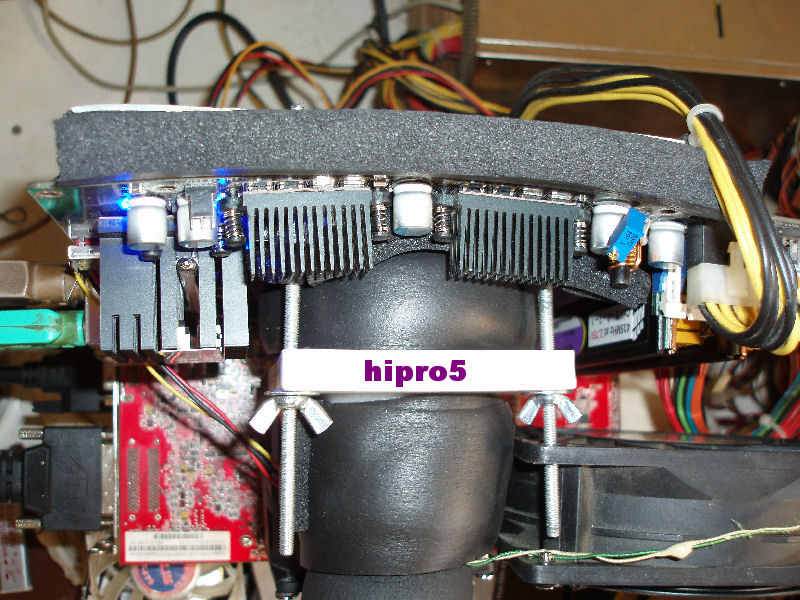
    a. Digital OR traditional VRM with ALL the Mos-Fets in ONE LINE (straight) and cooling them with ONLY ONE heatsink, IS WRONG.....

    Why?......EVEN if a user place the DEFAULT Intel heatsink onto the CPU, the motherboard is NEVER going to be in a "straight line" - take a look at it from it's side - .....
    By this, the CENTRED Mos-Fets are getting WAY hotter than the sided ones....
    Imagine now that a user buys another CPU heatsink and he starts to squeeze it much more.....
    BIG mistake putting ALL Mos-Fets in one line with ONE heatsink on them.....

    Do you want to talk now about the enthousiasts with the cascades/LN2s?....You get an "S" shape motherboard.....

    I'm NOT talking about DFI here......I'm talking about ALL.....


    b. When using a Digital VRM Mos-IC-Fet, you encode two problems:
    1. TOO tiny surface to cool down with a heatsink and
    2. in case that some user wants to takes off it's heatsink and place another one on them, they are TOO delicate and they break VERY EASY....(Even a corner of them if it breaks you're s(crewed....


    c. NO MATTER how high switching frequency the Digital VRM you make to work for efficiency/etc., you CAN'T "filter" the "Voltage spikes" from idle to full load of a CPU.....
    By NOT using electrolytic capacitors ALSO ADDED on their output circuit so to "catch" (filter) better those voltage spikes and "walking" on the reference design of Voltera (for example), you're doing NOTHING....


    My thoughts:

    a. If you want to use Digital it's OK BUT place those Mos-IC-Fet by TWO (and only OR by 4 in a square) with a quite big heatsink on them (forget heatpipes and crap like this)....
    b. ADD some elecrolytic capacitors on their outputs...(SMDs like ASUS uses in some of their designs "catches" faster those voltage spikes - Vdroop of ASUS is another thing though and it has nothing to do with them - )
    c. Use AT LEAST 8 Digitals so by placing them in square, you will need only two quite big heatsinks which MUST NOT TOUCH each other with heatpipe or anything else in case the motherboard gets stretched by the CPU heatsink or so....
    d. DON'T use the "lined" chokes for the digital......when a user screws his mobo with the heatsink/LN2 pot/cascade, some of them break their ceramic cover and they become useless.....


    .
    Last edited by hipro5; 10-12-2007 at 02:15 PM.
    INTEL PWA FOR EVER

    Dr. Who my arss...

    .........


Bookmarks

Bookmarks

Posting Permissions

  • You may not post new threads
  • You may not post replies
  • You may not post attachments
  • You may not edit your posts
  •