


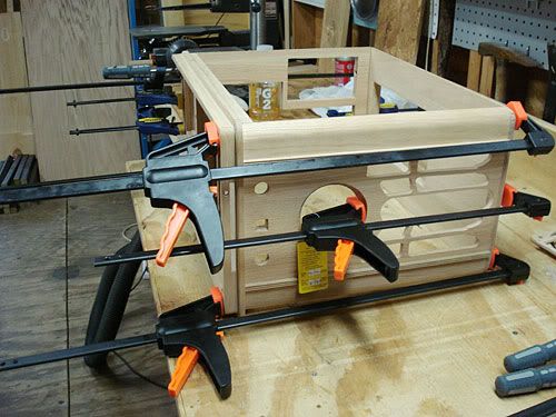
Base
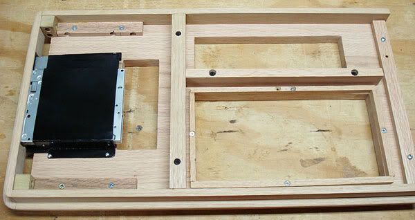
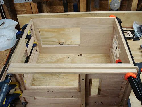
I added some cleats and mounted the base trim to the bottom piece. I screwed the base on instead of gluing as I want to be able to remove it should I need to make any adjustments to the DVD area later. My concern here is how well the slot loading DVD drive itself will hold up as I read mixed reports as to their reliability. I figure if I ever need to switch to a tray loading drive instead, I would want to be able to remove the base trim to adjust the front slot dimensions.
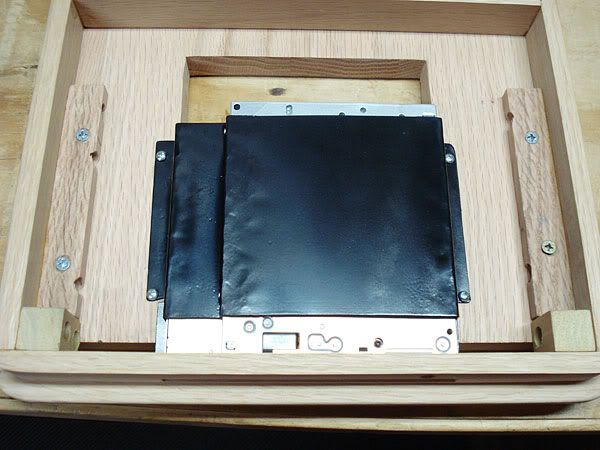
I made the mount for the DVD drive. This is made of one piece of 18 gauge aluminum that I bent using a bench vise, muscle, and hammering. I frankly wasn't expecting it to turn out the first time around, but it did. The drive is screwed into the mount.
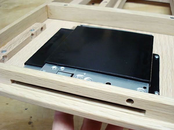
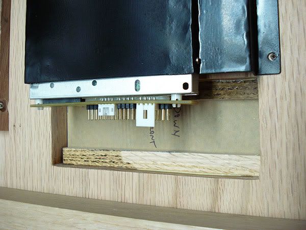
In my design, I left an open area above the drive for the cables to come through. I cut two cleats, and cut a piece of smoked acrylic (still has paper on in pic) into which I will cut slots for the cables. I want to use the SATA drive adapter board for the DVD drive that I bought, but it extends about 1/4" below the drive which makes it stick out below the bottom trim. The IDE drive adapter sits flush with the drive bottom, so I may be stuck using the IDE adapter board that came with the drive instead.
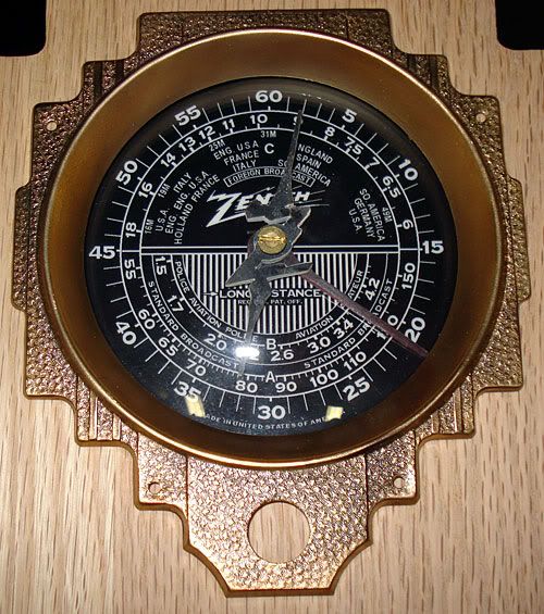
Dial Needles and Mounting
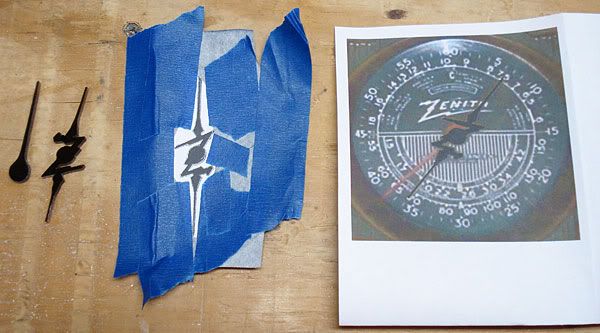
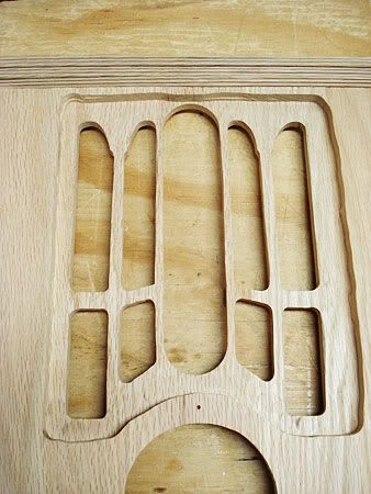
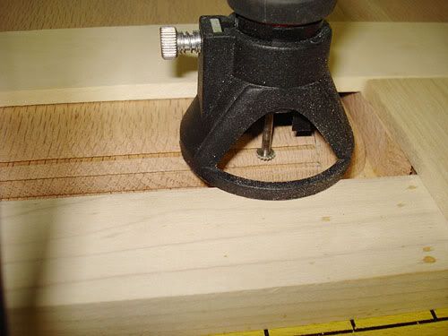
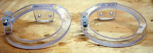
I wasn't able to get original needles for the dial, so I made my own ones. I am very pleased with the way this has turned out. It took quite a bit of fiddling with this to make it work. I had a good front pic of the dial area of the case that I resized in Photoshop to the actual dial dimensions. I traced the "Z" needle onto a new layer in PS, printed that layer out, taped it onto carbon paper with blue painter's tape, and traced and cut out the pattern on some 1/8" smoked acrylic. I mistakenly painted the needles first before drilling the center hole, so I had to sand them back down and after fitting later repaint them. I also used a dremel and thinned out one of the needles to be less than 1/8" so that they would easily under the dial glass.
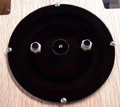
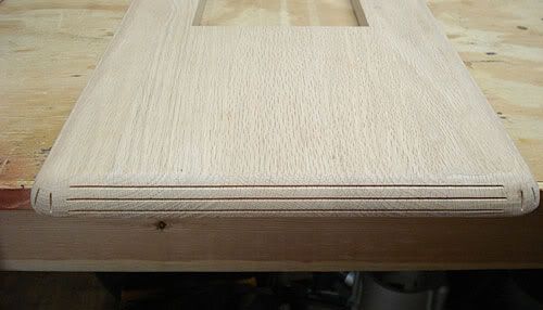
I cut a circle larger than the hole area, mounted it to the backside, and drilled holes for 2 metal LCD mounts.
There is a short piece of 3/8" dowel going between the back mount and the dial and needles so that the needles can be tightened into place without pulling back on the dial. I will fill in the slot on the screw with a bit of caulk and put a drop of white paint on it after it is mounted permanently so that the brass and screw slot aren't visible.
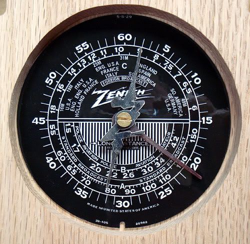
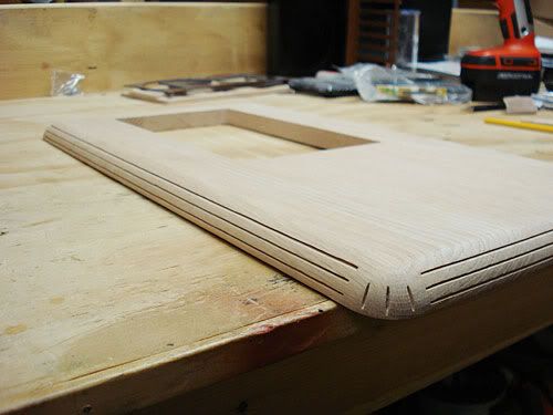
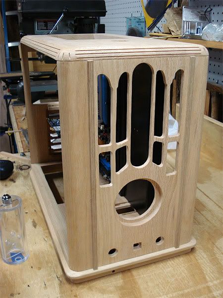
This is with the hole dial in place to give you an idea of how it will look. The needles will of course be painted their respective white and red.
Reservoir- Making One and a Guide
I haven't been very impressed with most of the commercially available reservoirs in my time watercooling. There are a few good ones, but with those of course you are limited to their layout and design. Especially since I have gotten into making my own cases the last few years, making my own reservoir to my own size/layout has worked well for me. I have tried and used T-lines before, and frankly I don't like them. I like the ease of bleeding and filling associated with my reservoir designs much better. So if you happen to hate reservoirs, I just say to each his own!
I wanted to take a bit of time to explain a bit more in depth how to make a reservoir should others be interested. I have yet to find a guide that tells how to do this. There are many ways to make reservoirs. Mine is only one way. But this way is what I have come up with over several years of trial and error that works for me and has proven 100% reliable. I capillary solvent weld cast acrylic together with no o-rings to keep the res watertight. This is a means of making a res that most do-it-yourselfers can manage with just plain hand power tools. If you have a better way to do this, by all means share your input as this is by no means an infallible guide.
Making your own res will probably cost you a bit more up front, and takes some time to get used to, but it gives you a flexibility in design and options that you simply cannot buy. Usually when I buy materials to make a res, I can make 2-3 identical reservoirs for the same cost it takes to buy a commercially made one.
--Reservoir Design
I have found so far that in deciding how exactly to design the reservoir, I first decide how to best fit a reservoir into the case/loop I am working on. One of the reasons for making a custom res in the first place is to tailor it to the loop/case, not vice versa. Once I get the barb placement figured out, then I design the internals. I like the top of my res to go directly to a top mounted fillport for easy filling. I also need a bottom barb to go to the pump inlet. In general, I try to place my reservoirs as close to the top of the loop as possible.
When it comes to how to design the internals, this is generally how I go about designing the res. I want the water to have to change directions, and not have an easy, direct path to the outlet/pump inlet. If it is very easy for water to go from one barb internally to the next, it will take air with it and the loop will be slower to bleed. I also allow a place for air to trap at the top of the res.
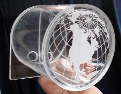
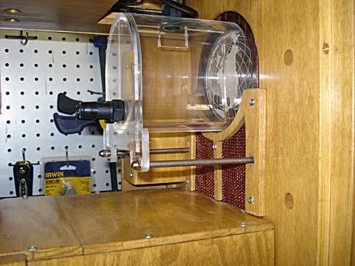
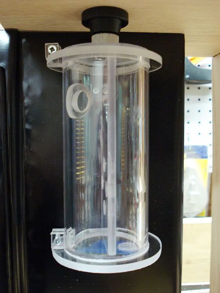
Here are a few pics of the last res that I made that I have been using for over a year. I used 4" cast acrylic tube mounted horizontally. There is a 1/4" gap between the divider and the front of the res, so that water has to go through the res from one barb to another to exit. This design has worked very well in bleeding quickly since the water has to travel which gives air time to easily rise to the top. The globe etching in the front was courtesy of Dennis at Dangerden. He responded to a forum post request and did this for me.
This is the way it is mounted.
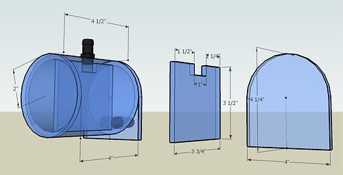
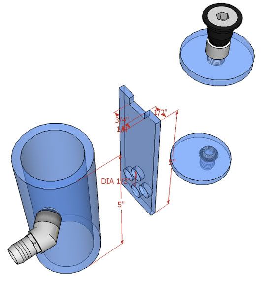
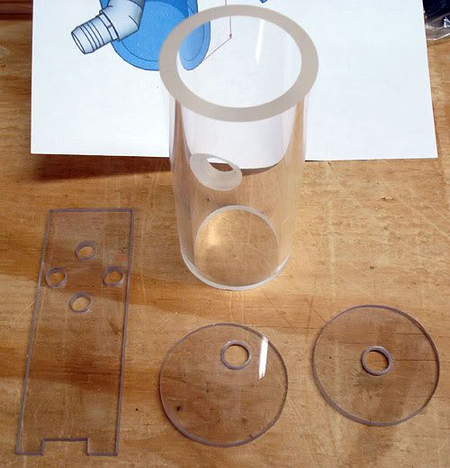
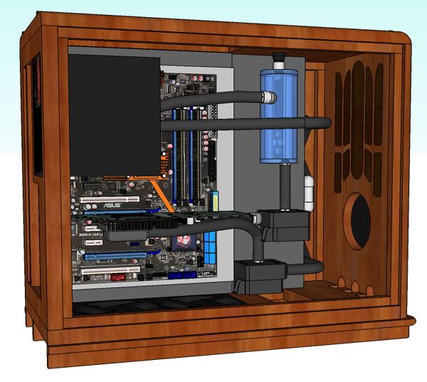
On the current res I am making for this case project, I decided on a narrow 2 1/4"OD 1 3/4"ID cylindrical tube 5 1/2" long total, or 5" minus end caps. The barb going into the res is placed high in the res due to the line going from the CPU to it. If possible, I want the res inlet to be above the CPU block so that air doesn't get trapped in the CPU block. I am making an internal divider that the water will hit before it goes anywhere else. This hopefully will draw bubbles to the top and fillport. I also placed a few holes further down in the divider that are 3/8" dia to let water through but hopefully help keep air from heading straight to the outlet. The divider doesn't quite go all the way down to the bottom. There is about a 1/32" gap between it and the bottom so that both sides will drain. I sure don't say that I have "the word" on res design, but hopefully this will help you work through the design if you make one.
--Starters
Rectangular reservoirs are harder to make since the cuts on the rectangular pieces have to be absolutely square. I have found it much easier to make cylindrical reservoirs. When getting acrylic to work with, get CAST acrylic only. DO NOT USE extruded acrylic for any of the pieces. If acrylic doesn't say what it is, it is extruded. You specifically need to buy acrylic that is cast. Without going into too much detail, cast acrylic is much harder and machines much better. Acrylic is a great material, but somewhat quirky, and heat is a major problem with acrylic. Cast acrylic doesn't heat up anywhere near as much as extruded does, and when machining extruded acrylic for a project like this, it is very easy to end up with problems.
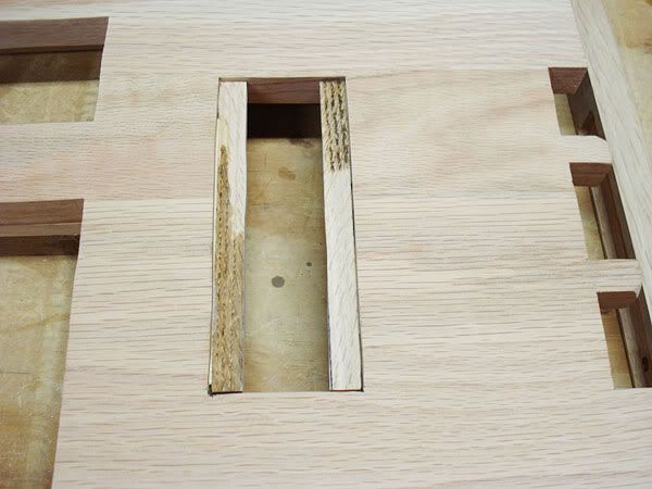
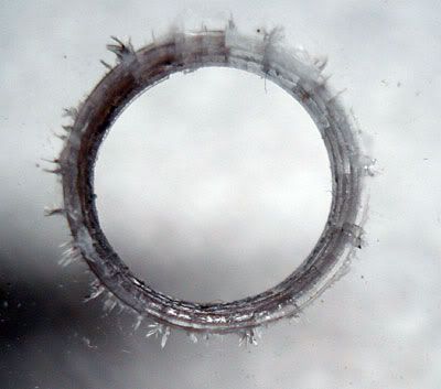
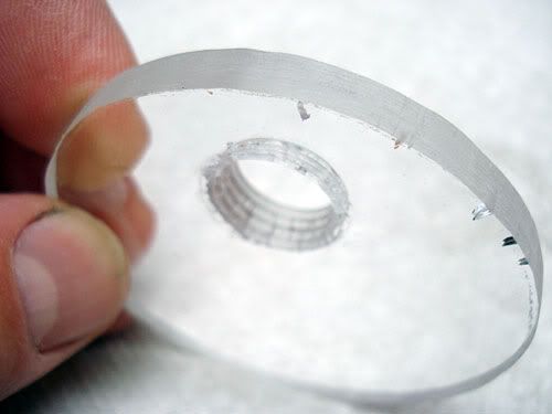
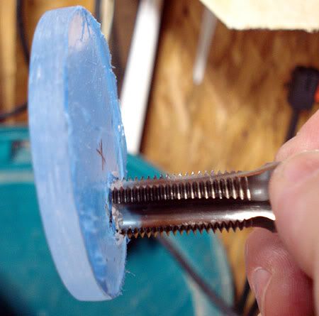
Here is what can happen if you try to cut out, drill, and tap extruded acrylic. The small cracks that can be seen are called crazing, and basically are the result of the acrylic heating up too much when machining (too much stress on the material).
The only place so far that I have found cylindrical cast acrylic in 1' lengths is mcmaster-carr (mcmaster.com). They also have sheet cast acrylic, and round laser cut dials for the ends in 1" increments made out of cast acrylic. If you can make your res so that you can use precut round laser ends, do it. Cutting the ends can be a bit of a pain to get them round. The cast acrylic for the ends and divider that I used for this I got off of Ebay. I had to cut my own ends as I can't find precut cast ends for the 2 1/4" dia of my res. I buy cast cylindrical pieces only that are no less than 1/4" thick. The ends can be 3/16" thick, but no less as this gives adequate depth for threads for barbs. 1/4" thick for the cylinder gives a good large surface to work with when solvent welding.
--Solvent Weld
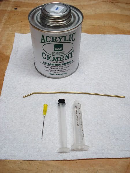
The best stuff for solvent welding the ends on is either IPS Weld-On #3, or TAP Acrylic cement (same thing) from tapplastics.com. A 4oz jar will do several reservoirs. You also want to get the needle type gauge applicator (16 gauge hypo). The needle applicator gives you very good control of how much solvent you use, whereas the bottles don't. You'll get solvent everywhere if you use them. While you are there, if you solvent weld acrylic for other purposes, you can pick up a tube of IPS Weld-On 16. It is a lot thicker and is handy for gluing together acrylic in general, but for this reservoir purpose, it leaves far too many bubbles in the seam. If properly used, this solvent weld will hold all day long at 10 times the pressure that we have in our watercooling systems.
In order to get solvent from one end to the other, I use a piece of small brass tubing that I bought locally for about a $1 at an ACE hardware store. I bent the end to make it easier to get into the bottom seams.
--Begin the Res Build
The first thing you want to do in building a res is to cut out all of your parts, sand whatever needs sanding, drill whatever needs drilling, and tap any thread holes. You want to do all of this first so that you don't get any debris stuck in the res once its together, and you will need the barb holes to feed through to get solvent into at least one end. It took me < 1 1/2 hours to cut all of the pieces, sand all of the edges, and drill and tap the holes. If you can use laser precut ends, it would save probably 30min.
The first thing you want to do in building a res is to cut out all of your parts, sand whatever needs sanding, drill whatever needs drilling, and tap any thread holes. You want to do all of this first so that you don't get any debris stuck in the res once its together, and you will need the barb holes to feed through to get solvent into at least one end. It took me < 1 1/2 hours to cut all of the pieces, sand all of the edges, and drill and tap the holes. If you can use laser precut ends, it would save probably 30 min.
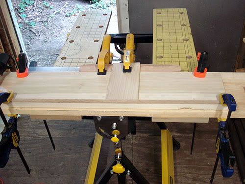
To cut the cylindrical piece of cast acrylic, I used a compound miter saw with a plywood blade. You can cut this also by hand with a simple $15 miter box. The cut however needs to be perfectly straight. If cutting with a power miter saw, don't try to cut straight through the acrylic. Use an up and down motion with the saw to cut a bit at a time. Remember, acrylic doesn't like heat so cutting in an up and down quick chopping fashion a bit at a time doesn't heat up the acrylic as much. I probably used 20-30 small up and down chops to cut the end.
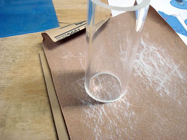
Once cut, you need to get rid of all of the saw marks. I do not recommend using any power sanders for this. They tend to heat up the acrylic too much and can cause crazing when solvent welding. I sand the ends smooth by hand using a flat surface and some elbow grease. I slowly rotate the tube as I sand. I recommend sanding all the way to 400 grit (100, 150, 220, 400). It took me about 30 minutes to sand smooth both ends.
--Barbs
As for what barbs to use, on every other res I have made, I used 3/8"NPT - 1/2" (3/8"threads x 1/2" barb) plastic barbs that I bought from ACE hardware. A 3/8"NPT tap to cut the thread holes can be had for about $5. NPT are tapered threads, so you would want to use plastic barbs to minimize the stress placed on the acrylic by the tapered holes with barbs tightened in them. If you try to put a brass tapered barb in a tapered hole in acrylic, you will probably cause it to craze. A bit of RTV silicone sealant is all that is needed to seal them up.
On this res, I bought a G1/4" thread tap from mcmaster. It is item no 8328A22 (search for it- G1/4"-19 BSPP thread tap) and sells for $17 + shipping. The metal barbs used for watercooling as most of us know use G1/4" British Standard Parallel threads. This really is an even better solution for using with acrylic as putting a parallel threaded barb into a parallel threaded hole causes virtually no stress on the acrylic surrounding the hole.
--Tapping Holes
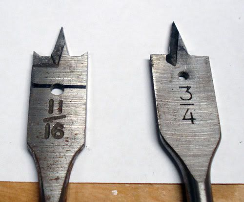
If you have tapped holes before, just skip this paragraph. In case you never have, when tapping the holes, you first drill a hole with the required size. G1/4" technically call for a ll.8mm (.46") hole, but a 7/16" (.44") bit works fine. I recommend using a wood spade bit over a forstner type bit. Wood spade bits don't heat up the acrylic nearly as much as forstner bits do. You then insert the thread tap, spray it with some kind of lubricant (I use spray silicone), and keeping the tap perpendicular to the hole work the tap back and forth into the hole, cutting a bit more thread each time with each turn. I take about a 1/4 clockwise, then counterclockwise just a bit, the 1/4 turn clockwise, back a bit, and so forth. Make sure to spray more lube a few times onto your tap and in the hole. Once the thread tap stops cutting, thread it all the way through and back out of the hole, and then thread it through the other side to clean up the threads.
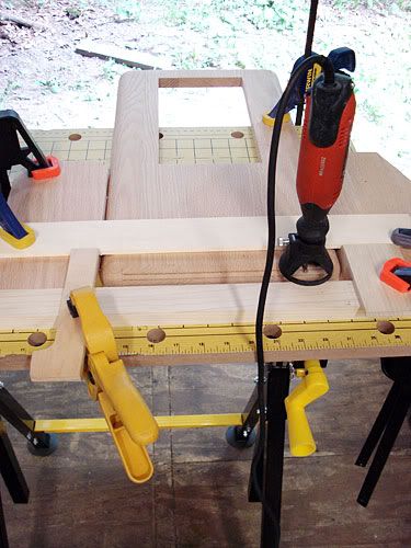
I had to use a bit of a different approach on the side inlet, as I am using a Bitspower 45 elbow which needs a flat surface for the o-ring to seal to. I took a regular 3/4" wood spade bit and using a grinder ground the side cutting surfaces to be flat. This way the hole would be flat and wouldn't go any deeper than I wanted.
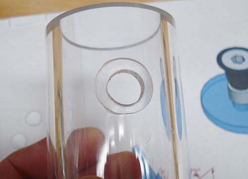
I clamped the tube onto a piece of 2" x 4" wood to keep it steady, and drilled the 3/4" hole in just deep enough until the entire 3/4" dia of the drill bit could be seen. This way I have a flat 3/4" area. I then used a regular 7/16" spade bit to finish drilling out the middle for the threads.
--Solvent Welding
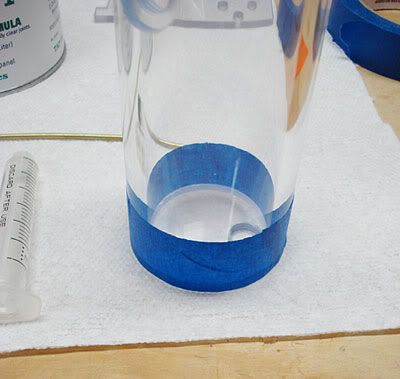
How that everything is cut and ready to use, it is time to put it all together. IPS Weld-On #3 and/or TAP plastics acrylic cement melt the edges and hence "weld" them together. This stuff is a thin as water. Welding with it is called capillary welding in case you want to Google it. I put one end on and hold it in place with blue painters tape. This way. when I put the solvent into the joint, it doesn't run all over the place on the outside.
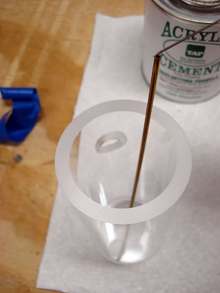
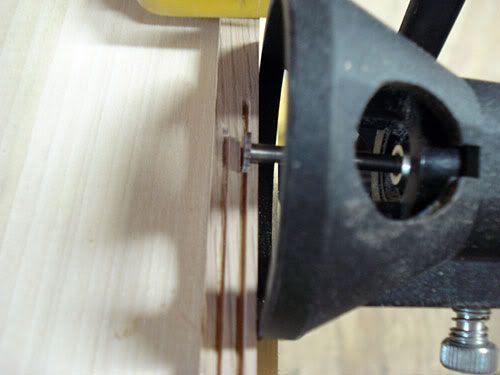
I use the brass tube from one end to reach the seam of the other end. You want to minimize getting solvent onto the acrylic as it clouds up whatever it hits. This is why i recommend the use of the syringe type applicator to put just a bit of solvent at a time into the joint (I took the tape off here just to show better how it works-I had already done this end).
You just squirt a bit of the solvent down the hole into the joint, working it all of the way around. It will go into the joint until it pools up on the inside. Once the joint won't take anymore, pull off the tape and gently squirt solvent into the seam from the outside all the way around. You can look from the bottom to see it going into the joint. Once you have gotten as much solvent as will go into all of the joint, press down on the entire tube and end hard for about a minute or so. This is to help minimize air bubbles. Holding the tube horizontally, I then put the middle insert where I wanted, ran solvent down the sides to attach it in place, and repeated the process for the other end.
If you end up with some small bubbles in the joint, it is nothing to worry about. I have never had a res leak yet. The one I have been using now I have had in my current case for over a year.
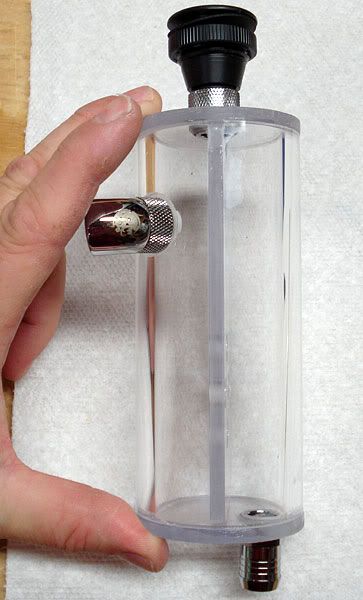
Here is what the res looks like with all of the barbs in place.
--Other Thoughts
I didn't build a mount into the res itself, as I will be making a separate piece for that, but you could easily modify the bottom piece to incorporate a mount. In the res I've been using for over a year, I did incorporate a mount into one end. It however has the tube laying horizontally instead of vertically.
Once done, I will let it sit for a few days before doing anything with it. Although the solvent dries quickly, it takes days for the joint to form maximum strength. I will then pressure test it with air pressure to about 30psi or so to make sure it is solid. If it holds 30psi for an hour, it isn't going to leak.
I'm sure there is more detail that I could put into this, but seeing as I have spent the last 2 hours on this, I think I've said enough. Others I'm sure can chime in with more information and clarification, but hopefully this will help someone looking to make their own res. Without the use of a lathe or something to cut channels for o-rings on the ends, this is a workable method for making a dependable, leak-free res with just a few basic hand power tools.

 Reply With Quote


 Join Us in the XS World Community Grid Forum & Help Fight Cancer and Other Diseases


Bookmarks