Page 2 of 3 FirstFirst 123 LastLast
Results 26 to 50 of 52

Thread: Pros and Cons of Digital PWM?

  1. #26
    X.I.P.
    Join Date
    Dec 2003
    Posts
    61
    Quote Originally Posted by STaRGaZeR View Post
    Yeah, I know how Vdroop works, and I really donīt want it. Stable voltage is best for us XS members. Asus, DFI, Gigabyte... must implement an option in the BIOS to let us rock stable voltage under load, or a max of 0.01v~0.02v, like CPU Voltage Damper does in lastest Asus boards.

    I measured it with the Smartguardian utility, didnīt know how to read it with a multimeter. Anyway, SM confirms what I saw in my tests: with the same CPU, Asus and my current Intel board behaviour is the same. Both measured with a well calibrated multimeter, after vdroop it needs 1,19v to a stable 3.3Ghz, a little OC. With the iCFX3200, 1.35v in BIOS resulted in a 1,28v idle (no problems here, typical Vdrop), but at load, it dropped to about 1,20v. At that voltage it should be stable like it was on Asus and Intel, but it wasnīt, 1,25v or 1,30v didnīt fix it. Even at that low OC, that huge voltage fluctuations kill the stability. I played with the iCFX for about a month, trying to understand what I was doing wrong, but honestly, I think that the problem was a faulty board or something, not me. I really liked all the BIOS options, great board, but the voltage related stability issue forced me to get rid of it.
    There is Vdroop disable circuit in some of our P35 board , we will put this circuit in all future board with Digital VRM(except AMD board , AMD does not define clear Vdroop design guideline in their power spec) ...

    SG utility is not calibrated unlike your reading in bios ... We have ask ITE to give us SG source code , we are working on it and try to see if we can make it more close to BIOS reading(which is calibrated) ...

    About how much voltage to have stable over clocking result , I think it's vary from single board to another(even the same model) , so I can not comment too much what's the real reason you can get stable oc as other board unless I can get them and test by myself to see what's the possible root cause ...

  2. #27
    Xtreme Mentor
    Join Date
    Nov 2006
    Location
    Spain, EU
    Posts
    2,949
    Oh I see, thanks

    Yeah, stable voltage changes in single motherboard to another, but in this case uping it waaay up didn´t help.

    I´m curious about what DFI is going to bring us related to X38, maybe if it is on time and voltage Vdroop disable option is present, I´ll give it a chance. Maybe you should put it clear in the package and specifications, I´m sure many folks will like it.

    And please, no more green crap in the LanParty series, orange rocks. Keep us far away the heatpipe madness too, with the no transpiper version abailable since board launch date
    Last edited by STaRGaZeR; 10-05-2007 at 01:59 AM.
    Friends shouldn't let friends use Windows 7 until Microsoft fixes Windows Explorer (link)


    Quote Originally Posted by PerryR, on John Fruehe (JF-AMD) View Post
    Pretty much. Plus, he's here voluntarily.

  3. #28
    Xtreme Addict
    Join Date
    Nov 2005
    Location
    PHX
    Posts
    1,494
    Wow...really good info here guys. Thanks Oskar...can't wait to get my P35 all UVed up.

  4. #29
    Xtreme Enthusiast
    Join Date
    Jun 2004
    Location
    lake forest, CA
    Posts
    787
    Yea, great info. Oskar thanks for the help.

  5. #30
    Banned
    Join Date
    Jul 2004
    Location
    Scotland
    Posts
    926
    The Voltage Droop is in the Intel mobos as Intel makes the vendors add it.

    Asus mobos always overvolted slightly on AMD.
    Last edited by humeyboy; 10-05-2007 at 08:20 AM.

  6. #31
    Xtreme Member
    Join Date
    Feb 2004
    Location
    PT - Fig Foz
    Posts
    122
    There are a lot of vantages for the digital pwm, besides of voltage control.
    One of the essencials for me its a clean cpu socket zone

    Compare this to that

    And for the heat there is always solution

    The guys who said there is a vdroop on PWM Digital should try DFI P35 and see it, now with PWM Dig 8 Phase i've never seen a board so stable out of the box.

  7. #32
    Xtreme X.I.P.
    Join Date
    Feb 2006
    Posts
    2,741
    Quote Originally Posted by OSKAR_WU View Post
    8 . In my personal opinion , with proper design in heat dissipation , the only cons is the price too high ... The other problem is the supply is not too good compare to traditional VRM , maybe this is why 1st tier player can not use it , they can not use a design which has supply problem ...
    Oskar here in number 8 are you referring to parts availability for tier 1 who need big bulk orders?


    regards
    Raja

  8. #33
    Xtreme Member
    Join Date
    May 2004
    Posts
    358
    The Digital PM on the DFI Boards get so hot with liquid cooler they shut the boards down. a fan is need to provide some airflow around the area to keep things in check. We also add some heat sinks to the chips.( The little Blue ones next to the Block)
    [/IMG]
    Asrock Extreme3 Gen3
    Intel 2500K @5.0 1.52V
    Thermaltake Frio
    4-4GB Kinston HyperX 1600's
    1-256Gb Crucial M4 SSD
    Xion 1000W (Made by Superflower)
    2-Evga GTX570 in SLI
    Antec DF-30
    Windows 7 pro 64 bit

    Just a regular guy, Not Xtreme!!

    If I sound STUPID!! it is because I am.

    Not everyone can be a Genius!!

  9. #34
    Registered User
    Join Date
    Sep 2007
    Location
    Serbia
    Posts
    2
    My baby has a high temperature.
    Blood Iron, CPU E2160
    Attached Thumbnails Attached Thumbnails Click image for larger version. 

Name:	orthos DFI Blood Iron.png 
Views:	857 
Size:	191.7 KB 
ID:	65312  

  10. #35
    Xtreme Addict
    Join Date
    Nov 2005
    Location
    PHX
    Posts
    1,494
    That looks like a lack of airflow in the case...or high ambient temp.

    And the pics comparing the Asus P5E3 Deluxe to the DFI...hilarious. The Asus looks like it's got warts. In contrast, the DFI's socket's gotta be one of the cleanest I've every played w/.

    EDIT: fixed
    Last edited by Jodiuh; 10-12-2007 at 03:44 PM.

  11. #36
    Xtreme 3D Team Member
    Join Date
    Jun 2006
    Location
    small town in Indiana
    Posts
    2,285
    nice to have your input on this oskar. i use phase change cooling so the digital is far easier for me to insulate and the temps are very reasonable. my ICFX3200 actually stayed around 0c according to sg.

    off topic: Oskar you have made a simply stellar board with the DFI LP UT P35 T2R i am impressed even more every day. as i have said in other threads it is probably the finest intel board on the market. i can't wait for the x38 version also.

    ot 2: oskar when you release a board like the x38 lp could you possibly post up an overveiw of the bios parameters and tweaks. I know Andre and others work really hard to get us enthusiasts the info we crave but it would be awesome to have the engineer's input.
    QX 9650 5ghz with 1.55v 4.8ghz with 1.5v 24/7 in a VAPOLI V-2000B+ Single stage phase cooling.
    DFI LP LT X-38 T2R
    2X HD4850's water cooled , volt modded
    Thermaltake 1KW Psu
    4x Seagate 250GB in RAID 0
    8GB crucial ballistix ram

  12. #37
    k|ngp|n/Sham my brothers
    Join Date
    Aug 2002
    Location
    Athens---Hellas
    Posts
    5,693
    Quote Originally Posted by OSKAR_WU View Post
    When the cpu load changes , no matter how fast the VRM can respond , there is always a very short period you need to use the Choke and Capacitor to maintain the voltage stable ... If we can design unlimited capacitor on the board , we can remove the droop design when the capacitor can handle all these transient state , but that's not possible ...
    From the schematics you have uploaded, users can see how the power circuit responds from heavy load to light load (idle) and visa-versa.....

    a. Digital OR traditional VRM with ALL the Mos-Fets in ONE LINE (straight) and cooling them with ONLY ONE heatsink, IS WRONG.....

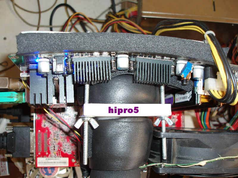
    Why?......EVEN if a user place the DEFAULT Intel heatsink onto the CPU, the motherboard is NEVER going to be in a "straight line" - take a look at it from it's side - .....
    By this, the CENTRED Mos-Fets are getting WAY hotter than the sided ones....
    Imagine now that a user buys another CPU heatsink and he starts to squeeze it much more.....
    BIG mistake putting ALL Mos-Fets in one line with ONE heatsink on them.....

    Do you want to talk now about the enthousiasts with the cascades/LN2s?....You get an "S" shape motherboard.....

    I'm NOT talking about DFI here......I'm talking about ALL.....


    b. When using a Digital VRM Mos-IC-Fet, you encode two problems:
    1. TOO tiny surface to cool down with a heatsink and
    2. in case that some user wants to takes off it's heatsink and place another one on them, they are TOO delicate and they break VERY EASY....(Even a corner of them if it breaks you're s(crewed....


    c. NO MATTER how high switching frequency the Digital VRM you make to work for efficiency/etc., you CAN'T "filter" the "Voltage spikes" from idle to full load of a CPU.....
    By NOT using electrolytic capacitors ALSO ADDED on their output circuit so to "catch" (filter) better those voltage spikes and "walking" on the reference design of Voltera (for example), you're doing NOTHING....


    My thoughts:

    a. If you want to use Digital it's OK BUT place those Mos-IC-Fet by TWO (and only OR by 4 in a square) with a quite big heatsink on them (forget heatpipes and crap like this)....
    b. ADD some elecrolytic capacitors on their outputs...(SMDs like ASUS uses in some of their designs "catches" faster those voltage spikes - Vdroop of ASUS is another thing though and it has nothing to do with them - )
    c. Use AT LEAST 8 Digitals so by placing them in square, you will need only two quite big heatsinks which MUST NOT TOUCH each other with heatpipe or anything else in case the motherboard gets stretched by the CPU heatsink or so....
    d. DON'T use the "lined" chokes for the digital......when a user screws his mobo with the heatsink/LN2 pot/cascade, some of them break their ceramic cover and they become useless.....


    .
    Last edited by hipro5; 10-12-2007 at 02:15 PM.
    INTEL PWA FOR EVER

    Dr. Who my arss...

    .........


  13. #38
    Xtreme Guru
    Join Date
    Aug 2003
    Location
    Athens, Greece
    Posts
    3,656
    Very nice read, as always, George!
    Project ZEUS II

    Asus Rampage II Extreme
    Intel I7 920 D0 3930A @ 4.50GHz (21 X 214mhz)
    3 x 2GB G.Skill Trident 1600 @ 1716MHz (6-8-6-20-1N)
    2 x Asus HD 6870 CrossFire @ 1000/1100MHz
    OCZ Vertex 2 60GB | Intel X25-M 120GB | WD Velociraptor 150GB | Seagate FreeAgent XTreme 1.5TB esata
    Asus Xonar DX | Logitech Z-5500 | LG W2600HP 26" S-IPS LCD

    Watercooling setup:
    1st loop -> Radiator: 2 x ThermoChill PA120.3 | Pump: Laing DDC-3.25 with Alphacool HF 38 top | CPU: Swiftech Apogee XT | Chipset: Swiftech MCW-NBMAX | Tubing: Masterkleer 1/2" UV
    2nd loop -> Radiator: ThermoChill PA120.3 | Pump: Laing DDC-3.2 with Alphacool HF 38 top | GPU: 2 x EK FC-6870 | Tubing: Masterkleer 1/2" UV


    Assembled in Mountain Mods Ascension Trinity
    Powered by Corsair Professional Series Gold AX1200

  14. #39
    Banned
    Join Date
    Apr 2006
    Location
    Portishead, Bristol, England
    Posts
    3,248
    Quote Originally Posted by hipro5 View Post
    True bloody facts
    Very very nicely put there.

    Now why are all the MOBO MFGS focusing on having people like Oska oc'ing the willys off the bord when what they need in the first place is someone like Hipro that knows the facts both at the engiering aspect but end user.

    Hipro maybe you should get some mobo made of your own desgin, id pay for it

  15. #40
    k|ngp|n/Sham my brothers
    Join Date
    Aug 2002
    Location
    Athens---Hellas
    Posts
    5,693
    Quote Originally Posted by JoeBar View Post
    Very nice read, as always, George!
    Quote Originally Posted by Pete View Post
    Very very nicely put there.

    Now why are all the MOBO MFGS focusing on having people like Oska oc'ing the willys off the bord when what they need in the first place is someone like Hipro that knows the facts both at the engiering aspect but end user.

    Hipro maybe you should get some mobo made of your own desgin, id pay for it
    Thanks guys, but that's just facts....

    Oskar is a hell of technician you guys.....DON'T underestimate of him...

    Have you guys ever thought that he's NOT alone?...He just CAN'T do whatever he wishes.....He's an employ.....So in some cases/designs sometimes "other people" may tell him what to put on or off of a mobo.....what parts for example.....cheaper, etc......

    IF "they" leave him alone, I bet he could do miracles...

    Another thing I whould also like to add :
    Manufacturers GET R.F. technicians TOO......We are NOT anymore at 33MHz....We are WAY HIGHER than that.....
    This is going (pointing) to anyone who can understand of what I'm talking about....
    Last edited by hipro5; 10-12-2007 at 03:27 PM.
    INTEL PWA FOR EVER

    Dr. Who my arss...

    .........


  16. #41
    Xtreme Legend
    Join Date
    Mar 2005
    Location
    Australia
    Posts
    17,242
    hipro it's simple

    make a little pot for the mosfets and stick some dice on it during the runs
    Team.AU
    Got tube?
    GIGABYTE Australia
    Need a GIGABYTE bios or support?


  17. #42
    k|ngp|n/Sham my brothers
    Join Date
    Aug 2002
    Location
    Athens---Hellas
    Posts
    5,693
    Quote Originally Posted by dinos22 View Post
    hipro it's simple

    make a little pot for the mosfets and stick some dice on it during the runs
    NOT that simple.....It won't "touch" ALL of them when mobo gets squeezed and changed it's "lined shape"...

    Take a look at the below photo and HOW a mobo could become to fully understand of what I'm talking about.....


    Now put me a "straight heatsink" on those (let's suppose) Digitals to cool them down.....


    EDIT: BUT I know why you said that!.....You want that OVP mod of the NVIDIA....

    .
    Last edited by hipro5; 10-12-2007 at 03:53 PM.
    INTEL PWA FOR EVER

    Dr. Who my arss...

    .........


  18. #43
    Xtreme Legend
    Join Date
    Mar 2005
    Location
    Australia
    Posts
    17,242
    lol biatch

    nah i'm serious

    also in terms of bending there is a solution for that too

    i could quote some nice pics MM posted a long time ago of his wooden board and rubber standoffs but CFB looking it up

    you get the idea though

    let me recap then ...... wooden/metal solid board for benching with good wide and fairly short rubber standoffs and DICE cooling on PWM and you are good to go....you will have no heat in that area of mobo and mobo should be dead straight mounted on the board..............i see no reason why it would get bend that badly
    Team.AU
    Got tube?
    GIGABYTE Australia
    Need a GIGABYTE bios or support?


  19. #44
    I am Xtreme
    Join Date
    Nov 2002
    Location
    South FL, USA
    Posts
    4,892
    Quote Originally Posted by hipro5 View Post
    Thanks guys, but that's just facts....

    Oskar is a hell of technician you guys.....DON'T underestimate of him...

    Have you guys ever thought that he's NOT alone?...He just CAN'T do whatever he wishes.....He's an employ.....So in some cases/designs sometimes "other people" may tell him what to put on or off of a mobo.....what parts for example.....cheaper, etc......

    IF "they" leave him alone, I bet he could do miracles...

    Another thing I whould also like to add :
    Manufacturers GET R.F. technicians TOO......We are NOT anymore at 33MHz....We are WAY HIGHER than that.....
    This is going (pointing) to anyone who can understand of what I'm talking about....
    that last para flew over my head but those para's above that last read so TRUE to my eyes and ears!
    BIOSTAR TPOWER I45 UNOFFICIAL THREAD

    BIOSTAR TPOWER BOLT MOD FOR HEATPIPE AND HEATSINK

    BIOSTAR TPOWER I45 BIOS FLASHING PROCEDURE

    ABIT IP35 PRO HEATPIPE MOD

    ABIT IP35 PRO BIOS FLASHING PROCEDURE

    IP35 Pro: 9650@4000Mhz, par overclocker; Freezone Elite; 4Gb GSkill DDR-800@DDR-1068 (2 x 2gb); XFX 8800 GTS; Areca 8X PCIe in Raid 0 working at 4x speed; 4-250 Gb (single platter) 7200.10 drives; Giga 3DAurora case with side window.

  20. #45
    Xtreme Member
    Join Date
    Jul 2006
    Location
    U.S.A.
    Posts
    129
    and for all your troubles maybe this board should be given away for free too huh?

    Quote Originally Posted by STaRGaZeR View Post
    Oh I see, thanks

    Yeah, stable voltage changes in single motherboard to another, but in this case uping it waaay up didnīt help.

    Iīm curious about what DFI is going to bring us related to X38, maybe if it is on time and voltage Vdroop disable option is present, Iīll give it a chance. Maybe you should put it clear in the package and specifications, Iīm sure many folks will like it.

    And please, no more green crap in the LanParty series, orange rocks. Keep us far away the heatpipe madness too, with the no transpiper version abailable since board launch date

  21. #46
    Xtreme Batrachian
    Join Date
    Jan 2007
    Location
    Eastbourne, UK
    Posts
    1,368
    It has been mentioned before in the thread, but I also find digital PWMs a PITA from a mechanical point of view.

    With my (defunct) IN9 32X I found myself in a catch 22 situation, which I was never able to overcome, and ultimately led to irreversible damage (I crushed the ceramic encapsulation).

    With the default setup, and no OC, chips would shoot to what I understood as unreasonable 80-90 C.

    Same setup, mild OC (X6800 @ 3.33 Ghz), they would shoot to 99-108 C under load.

    Changing the thermal pad for a different type (the thick light blue one you often find in laptop GPU/VRegs) had no measurable impact on temperatures.

    Liquid TIM was a no-go with the default HS, as it had (wisely enough) "legs", which left a gap enough to run freely a green rizla between the HS and the chips. Filling such void with Ceramique or MX-1 was impractical.

    I looked at the possibility of making some sort of custom HS, but I didn't have at the time tools or a place to do so.

    I finally acquired a water block from mips.de, and decided to give it a try. The problem I faced was... torque.

    Too much and the PCB would warp leaving the centre chip with no contact whatsoever, and risk crushing the most external ones.

    Not enough and the block would tilt due to the traction/torsion of the tubing.

    The difference between "not-enough" and "too-much" was so little that achieving a good mount became a job for a 70 yr old Swiss clock maker.

    In the end, my patience run out, and with it my pulse. I heard a sound like someone stepping on wet sand, and there went my MB.

    In retrospective, even having used a back plate wouldn't have helped that much. Being the ceramic encapsulation so brittle, and with such tiny surface area, I doubt I would have managed to apply enough torque to leave the block sitting completely parallel to the surface without the same dreadful consequences.

  22. #47
    Xtreme Legend
    Join Date
    Mar 2005
    Location
    Australia
    Posts
    17,242
    does DFI get THAT hot as well
    Team.AU
    Got tube?
    GIGABYTE Australia
    Need a GIGABYTE bios or support?


  23. #48
    I am Xtreme
    Join Date
    Nov 2002
    Location
    South FL, USA
    Posts
    4,892
    digital PWM's, IMO, are fine at default clocking...but...once you start with the overclocking of a Quad core and then "jamming" with P95, you better have upgraded the cooling solution cause most times the current TIM under the HS will not keep up with the excessive temps produced by overclocking a Quad cpu.
    BIOSTAR TPOWER I45 UNOFFICIAL THREAD

    BIOSTAR TPOWER BOLT MOD FOR HEATPIPE AND HEATSINK

    BIOSTAR TPOWER I45 BIOS FLASHING PROCEDURE

    ABIT IP35 PRO HEATPIPE MOD

    ABIT IP35 PRO BIOS FLASHING PROCEDURE

    IP35 Pro: 9650@4000Mhz, par overclocker; Freezone Elite; 4Gb GSkill DDR-800@DDR-1068 (2 x 2gb); XFX 8800 GTS; Areca 8X PCIe in Raid 0 working at 4x speed; 4-250 Gb (single platter) 7200.10 drives; Giga 3DAurora case with side window.

  24. #49
    Xtreme Addict
    Join Date
    Dec 2006
    Location
    Vegas ,NV
    Posts
    1,636
    thank you oskar wu for your info, i enjoyed reading it.

    i wasnt exaclty sure what vdroop really was, till i read that. Lets hope for better designs in the future
    ~

  25. #50
    Xtreme X.I.P.
    Join Date
    Feb 2006
    Posts
    2,741
    Digital PWM supplies for Memory and Chipsets may hold some merit, especially for DDR3. The lower overall current draw will probably allow for the Dmosfets to supply their full bandwidth. Using DPWM in these areas will undoubtedly increase cost, but may well be worthwhile for outright performance based motherboards.

Page 2 of 3 FirstFirst 123 LastLast

Bookmarks

Bookmarks

Posting Permissions

  • You may not post new threads
  • You may not post replies
  • You may not post attachments
  • You may not edit your posts
  •