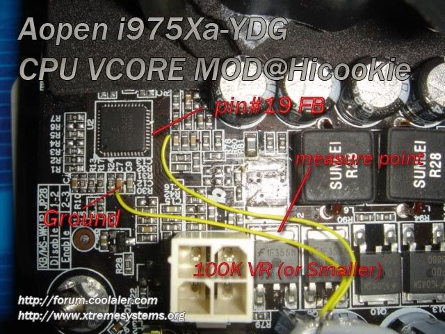
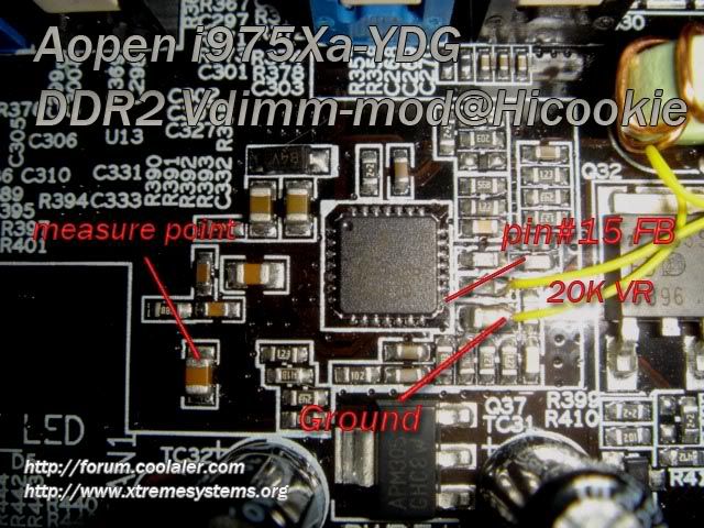
vcore-mod
vdimm-mod
Edit by runmc - hicookie I have removed this image untill it has been tested and your sure it is correct. thank you for your support.
vcore-mod
vdimm-mod
Edit by runmc - hicookie I have removed this image untill it has been tested and your sure it is correct. thank you for your support.
Last edited by hicookie; 04-23-2006 at 10:35 PM.
Do you know how high vcore will be at start if I put 50K VR for vcore mod?
Thanks
...
Thanx for sharing!
but, maybe I´m to stupid, could you explain al little more the NB V-Mod?
Is it right to solder from pin#2 to ground a 10 kOhm VR?
Last edited by stummerwinter; 04-07-2006 at 11:34 PM.
Originally Posted by NEW MODEL ARMY - the attack - 1984
Originally Posted by stummerwinter
His resistances are correct, but the wording is just a bit off.
He misused the term Vcore for the NB/Chipset mod.
The NB/Chipset is the 10K resistor mod, and Vdimm is the 20K resistor mod.
Very nice guide and pics. Thanks for sharing.
I like my women the way I like my processors...naked.
I am not the HellFire that writes bios files. I work strictly on voltage modifications.
Which Vdimmm is possible with that?Originally Posted by hicookie
Sry, to early, mixed up a few words...
Originally Posted by NEW MODEL ARMY - the attack - 1984
What do you mean: Which Vdimm is possible with that?
I dont understand what you are asking. Are you asking how high the Vdimm will go?
I like my women the way I like my processors...naked.
I am not the HellFire that writes bios files. I work strictly on voltage modifications.
vcore-mod vr i'm using 100k vr, starting at 1.5V(bios Auto voltage)
ddr2-vdimm, i tested 2.2V-2.6V working fine
intresting.
But have you managed to lift the bios fsb limitation ?
ibby
Originally Posted by ibby
What do you mean by "lift the bios fsb limitation"?
I like my women the way I like my processors...naked.
I am not the HellFire that writes bios files. I work strictly on voltage modifications.
i read some where that the bios was limited to 255mhz.
If thats the case, a vmod will not change that.
A new bios, or modded bios, is the only thing that can change bios settings.
I like my women the way I like my processors...naked.
I am not the HellFire that writes bios files. I work strictly on voltage modifications.
@hicookie: thanxOriginally Posted by hicookie
@hell-fire: thats´s what i want to know...
Originally Posted by NEW MODEL ARMY - the attack - 1984
if i measure at this point i get 1.2v if i set the vcore in bios to 1.5v, is it theOriginally Posted by hicookie
right measure point?
Heres Tcore mod (for cold boot problem @ subzero) from kyosen http://www.xtremesystems.org/forums/...postcount=1601
A L A R M .....
DON'T do the hicookie's VCore NB Mod coz IT'S NOT the NB Core....
It's the Vio of the i975 chipset and you'll measure NOTHING on the spot he pointed out for measuring.....You'll measure the REAL Vchip voltage BUT NOT coming from the regulator he's pointed out.....
WRONG REGULATOR........I just BLOW UP my AOpen mobo (Northbridge chip) by trimming the trimmer and NOT showing anything changing on the spot he has pointed coz there's NOTHING to do with this.......
It costed me 400$ this "Mod".......I was so anxious to mod my mobo that I thought not to search for Vchip Mod coz there was already be done by someone else, so I did this mod......BAD think......
QUESTION: @ hicookie....DID you do this mod on your mobo?.....DID you see changing by trimming the trimmer onto the measuring spot you are showing in your photo?......OR you just presume that this might be the VChip mod?.....
A L A R M .....
.
INTEL PWA FOR EVER
Dr. Who my arss...
.........
damn hipro.....no good mate
another German guy lost his board after this mod ...
that´s bad
hicookie don´t you test your modifications?
OK...what have I done wrong? Even after the mods, my vdimm is maxed out @ ~2.3V and the Vcore is maxed out @ ~1.64. In your pics you point to a specific pin on the IC's for the mods but you have soldered the wires to caps instead. Are we supposed to solder to the same caps? Or are we supposed to solder directly to the pin on the IC? I just assumed the solder points you used were alternate locations for the vmod, so I used the same. That may be the problem with my modsOriginally Posted by hicookie
sorry, i have not certify the nb vhip vmod....Originally Posted by C_B
is that problem mod image still there take it off dude
I got the same results...Originally Posted by Chri$ch
Which is the real VCore-measurepoint-point?
Originally Posted by NEW MODEL ARMY - the attack - 1984
sorry...
two questions... ^^
V/io voltage are originally how much.?
If MOD, is regulated from voltage that is established in bios..?
ex) Vcore(bios 1.3V) + Vcore MOD(?) = 1.3 + (?)
I made some measurements:
Set in BIOS <-> showed in BIOS <-> measure point from hicookie
1.250 V - 1.24 V - 1,006 V
1.300 V - 1.29 V - 1,084 V
1.350 V - 1.35 V - 1,072 V (!)
AutoVC - 1,37 V - 1,110 V
1.400 V - 1,39 V - 1,155 V
1.450 V - 1.44 V - 1,172 V
1.500 V - 1.48 V - 1,201 V
BIOS: 1.03
Mods: no
Originally Posted by NEW MODEL ARMY - the attack - 1984
any updates on how to fix it the right way?
I had vcore set to 1.5v in bios and it showed 1.49 on my mm using hicookie measure point. I checked it with a cheap mm I had and got low volts measurement. Then I checked it with a better mm with new batteries and got the above reading.Originally Posted by Chri$ch
Another view of the vcore mod.
Last edited by runmc; 04-24-2006 at 04:05 AM.
Bookmarks