


Hello there fella's, here's my report on the VoltMod.
I started out with a Club3D X800XL with 256MB of 2,0ns ram.
Standard the core would show artifacts at 450MHz, so I kept it at 440... but wanted more
The mem was of surprising quality and was running happily without any mods or cooling at 580MHz... I didn't hit the ceiling yet
So, the list-'o-facts:
Before the mod:
Vdd = 1.81 v
Vddq = 1.88 v
Vgpu = 1.41 v
RVdd = 1140 ohms
RVddq = 850 ohms
RVgpu = 436 ohms
RIgpu = 39.2 Kohms
After the mod:
Vdd = 1.952 v
Vddq = 1.999 v
Vgpu = 1.671 v
Below I will list only the value of the resistors that I added, you can calculate yourself what the actual resistance and Delta resistance on that spot is.
RVdd = 10.5 Kohms
RVddq = 14.45 Kohms
RVgpu = 2.29 Kohms
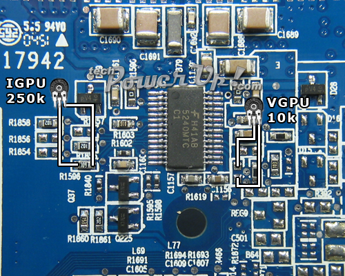
RIgpu = 250 Kohms
The Igpu resistor I left at 250 K because the GPU didn't crap out at 1.671 v.
Even adding the 250 K will lower the overal resistance so it nudged a little in the right direction anyway.
The pics!
Here it all begins, multimeter, tools, glasses and spare hard drives... just in case
Prepared the connectors for the resistors, so that they may be removed and installed when needed (I hate permanent solder mods).
In the top left corner you can see the WC blocks, ready for mounting when my Venice comes in.
Thos tiny little islands are too friggin... tiny!!!
But seemed to work...
Soldering to the chips was a lot easier, just hope no crap flowed under the chip...
This is how the connectors are mounted and how the resistors will be inserted into them.
You may wonder how I will keep them apart...
Well, like this! Some stripes to identify what goes where... simple as can be!
And this was the final setup.
Testing per resistor was easy, just put in little blue block, turn on pc and measure.
While the pc was on I adjusted the screw and saw the voltages change to what I wanted.
I'm sure the voltages can go higher with some fiddling and trying, but right now I'll leave it at a safe setting (at least I think it's safe).
Benches will follow after all work is done
Until the WC and ramsinks will be installed I removed the resistors not to stress it too much, obviously I won't just leave it running with the mod 24/7 sans cooling
Oh, while you're at it, why not take a look at my WC setup!
It's at My WC project
Forgive the crappy HTML, modding is my game, not art
Questions?
The next thing I am working on is to make the mod switchable!
I had a LCD display switchable with a signal from the printerport, but it's not stable or reliable enough to try it here, but a normal switch could do the trick! (switching 3 seperate rails with 1 flick of course)... working on it


 Reply With Quote


![Send a message via AIM to [XC] moddolicous](images/misc/im_aim.gif)


Bookmarks