-
Wire Diagram For Aquastream Xt Ultra & Aquaero
Can I please get a wire diagram from anyone specifically showing how all the wires gets connected on the pump & on the control monitor by indicating by picture, to & from between the Aquaero control monitor & to the Aquastream Xt Ultra pump. Im confused about all the conections on the back for the power & aquabus & usb & fan wires to and from control monitor & pump & onto the motherboard. I already have the english manuels & still cannot understand it & able to figure it out. 
-
Pump USB -> mobo
Pump Aquabus -> Aquaero
Pump Power -> PSU
Aquaero USB -> mobo
Aquaero Power -> PSU
-
Got a question or having a problem with your Aqua Computer product?
Contact us via
PM or
E-Mail.
-
Thanks shoggy for that pic.
1. On the back of the pump what about the connectors for the: "Fan" & the "RPM"
2. On the back of the aquaero what is Relais? the connection to what?
3. back of aquaero the "Flow" connection is for a flow meter only? right? Can i use a koolance flow meter?
4. Whats that 10pin connector "aquastream" in this pic get connected to?
5. the 3-pin "LED" connection is it for anything that has led lights needing power?
-
1.) On fan you can connect up to three fans (with y-adapters) depending on their load. You should not exceed a total of 6W. The aquastream ultra offers an automatic fan controller so you can control the fans depending on the water temperature which the pump also reads.
RPM generates several tacho signals depending on your configuration. For example you can generarte a static tacho signal which stops if the pump encounters a problem. Connected to a fan header of the mainboard you could enable a shutdown through the BIOS.
2.) The relais of the aquaero is usually used for an emergency shutdown. There are two ways to use it:
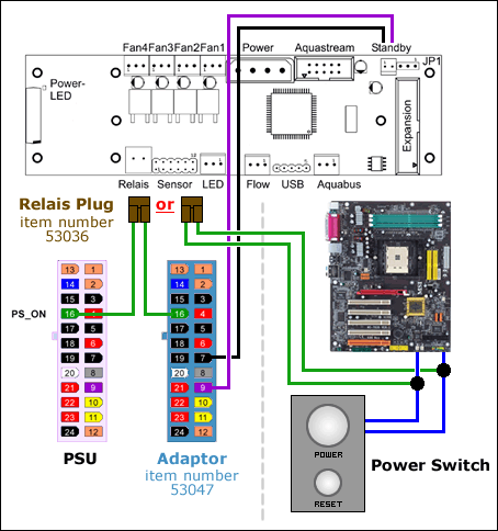
- using an optional ATX adapter or
- connecting the power switch of the case to it (parallel)
3.) Right, if you want to connect the FM17 I recommend to read this. It seems that its additional small PCB is causing some problems.
4.) You can ignore it. It was used for the old aquastream controllers:

5.) It is designed to be used with our multicolor LED module which has a two color LED (red and blue). You can set the brightness by hand, it can blink on alarm or you use it to fade from blue to red when a temperature goes up etc.
Of course you can also use your own LED(s).
Got a question or having a problem with your Aqua Computer product?
Contact us via
PM or
E-Mail.
 Posting Permissions
- You may not post new threads
- You may not post replies
- You may not post attachments
- You may not edit your posts
-
Forum Rules


 Reply With Quote
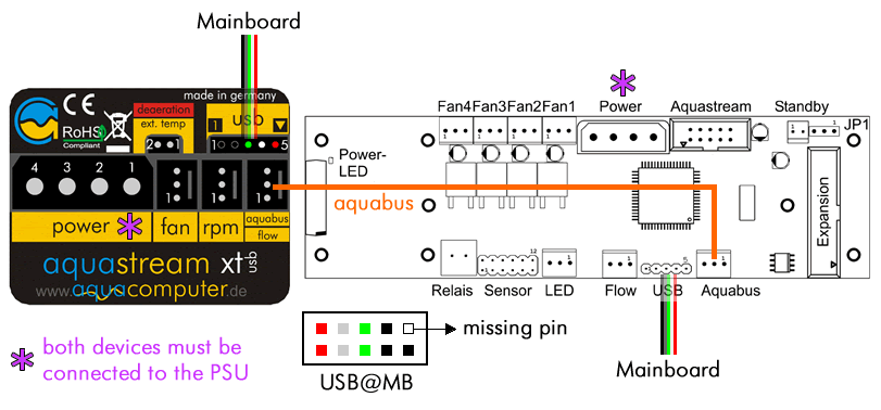

Bookmarks