


Hi there everybody.......
Sorry that I don't have time to write a complete article about the mods of the AS8 mobo but let's start it here......
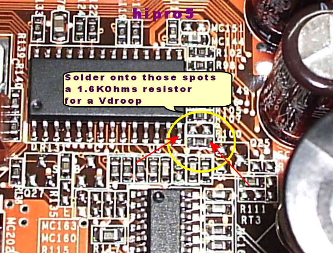
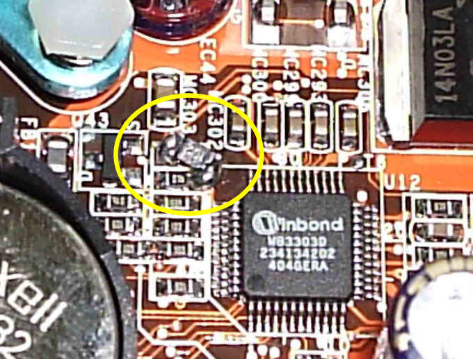
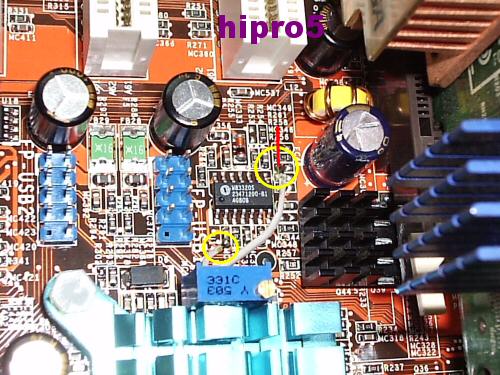
Let's start with the Vdroop mod.........AS8 mobo when you pick - let's say - 1.4VCore , it gives you at IDLE 1.35Volts and at FULL load about 1.31Volts.......YES it has a VCore droop problem.......To solve this problem we must do the below mod.......

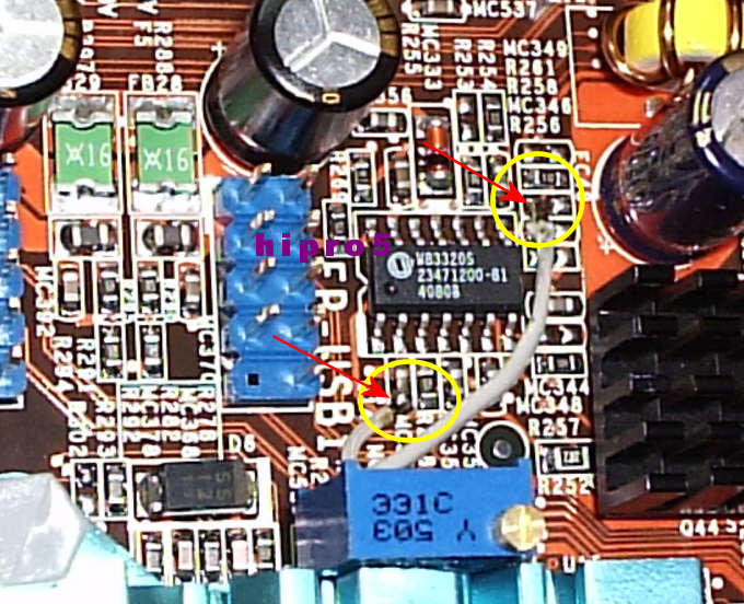
As we can see we solder one resistor of 1.8KOhms - BEST is 1.6KOhms - at leg 14 of this IC at the point showing on photo........In PARALLEL with the existing one.......and we are READY......With the 1.8KOhms we have a small droop at ONLY full load and not at IDLE........With a 1.6KOhms 1% resistor we are OK.......
EDIT : VDroop as it was BEFORE the mod........
EDIT 2 : we DO NOT UNSOLDER the existing resistor for the Vdroop mod........We just solder another one in PARALLEL with the existing one.......
VCore mod......
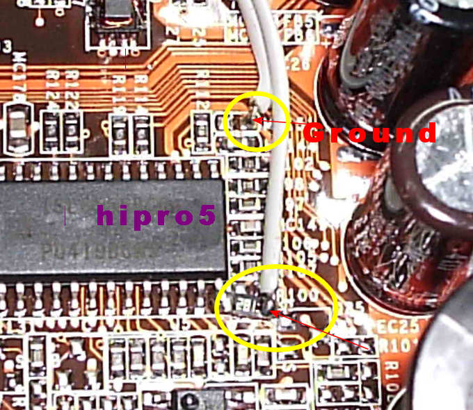
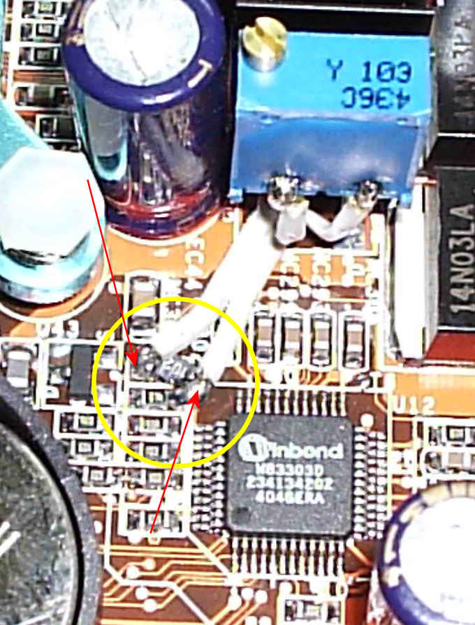
IF we want MORE VCore than the one that the mobo can provide as we can solder a 100KOhms trimmer at the spots in the photo below......We firstly trim it at it MAX resistance.......We solder one of it's side legs to ground and the middle one onto the spot in the photo........
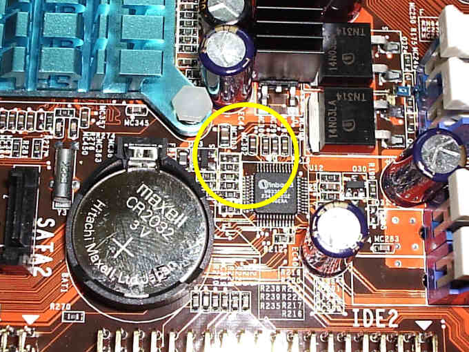
VChip(VNorth) mod.......
We track this Winbond IC - near and left of the CPU's slot - and we solder a 50KOhms trimmer in PARALLEL with the existing resistor.......Best is to trim it up to 1.52Volts.......MAX 1.72Volts........BUT IF you go for HIGH fsb you might need to trim it up to 1.9Volts max......With 1.72Volts you could reach up to 360MHz+ fsb.......
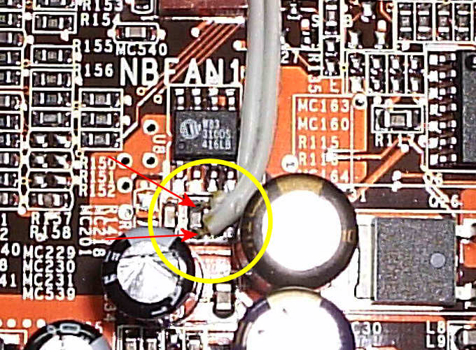
Vfsb mod......
By default it is at 1.21Volts.......The best I could get out of it was to trim it at 1.32Volts and no more.......
Track this area close to Winbond IC left to Ram slots.....
There must be a 0Ohms resistor there - IF I remember well coz I was in a hurry that day so as to boot this mobo with my new toy and I didn't pay that much attention to it - PLEASE someone confirm this.......
EDIT 3 : It IS a 0Ohms resistor......
Solder a 1KOhms resistor at the spots showing into this photo........
Solder a 10KOhms trimmer in PARALLEL with the soldered resistor of 1KOhms......and trim it at its MAX resistance......
Trim as you wish but the best I got was at about 1.32Volts.....
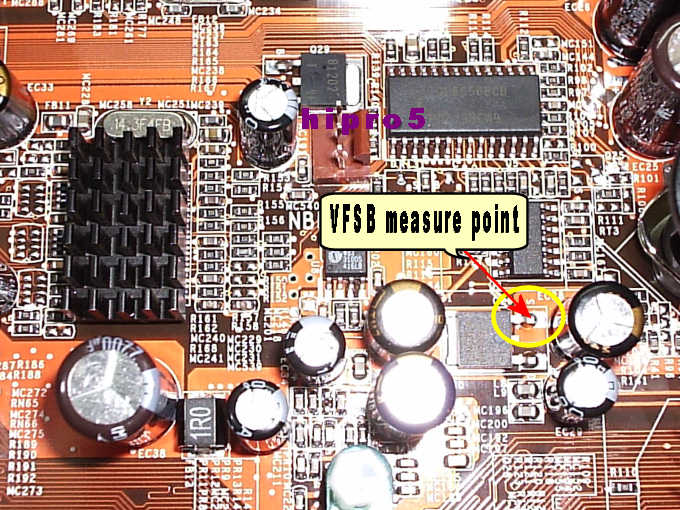
Here you can measure the VFSB..........
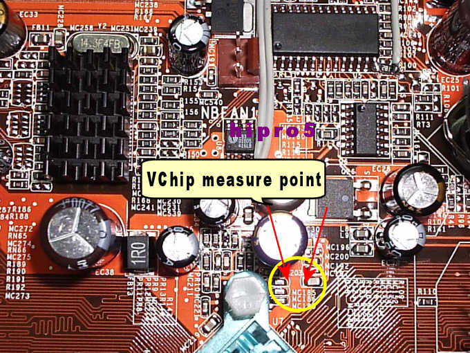
Here you can measure the Vchip............
VAGP mod...........
With this mod you can REALLY climb a bit higher at all confings : 1:1 , 5:4 , 3:2 .........
Trim it up to 1.95Volts if you wish..........
Solder a 50KOhms trimmer at those spots with in the photo below........
..........and a closer look..........
Trim it up to 1.95VAGP measuring it here.........
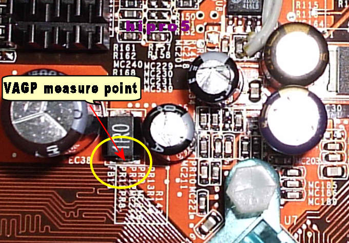
Measuring VAGP at the spot into the above photo , the real VAGP is about 2Volts.......When we trim it at 2Volts measuring at that spot , mobo will shut down from OVP........So just leave it MAX at 1.97 - 1.98Volts........If you encode a OVP VAGP problem , DON'T Panic......Just untrimm the VAGP trimmer with your rig shunted down - power off the PSU - and boot it up......
Vdimm mod isn't made coz I have my DDR Maximizer on it........
VTT IS tracked by the mobo quit well I could say by a Winbond IC on the right of the RAM slots.......So NO NEED to mod the VTT........
Just try to glue a heat sink onto this tiny chip coz it provides up to 2A VTT.......It needs a heat sink.......like the photo below........
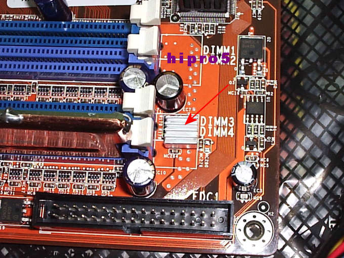
The SAME VTT chip is onto the MSI mobo too........
You could solder some 1500 - 3300uF/6.3V low esr electrolytic capacitors on the backside of the mobo if you wish for better VCore stability like the photo below........
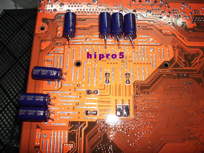
.......and some 100nF to 1uF NO POLAR SMD caps too.........
You can glue some heat sinks ALL over the place if you'd like to.......

Pay attention to trim out all trimmers at their MAXIMUM resistance before powering up you mobo and I wish you GOOD LUCK and may the "BLUE" force be with you........and feel free to ask anything you want........Thank you......


 Reply With Quote


 !!!STICKY!!!!


Bookmarks