

Yes.
That pin is connected to the light brown area just "below" it which is where I have soldered my wires to (have to scrape away the protective coating over that light brown area).
Be carefull not to contact the other pin next to it.


Yes.
That pin is connected to the light brown area just "below" it which is where I have soldered my wires to (have to scrape away the protective coating over that light brown area).
Be carefull not to contact the other pin next to it.
All along the watchtower the watchmen watch the eternal return.
But from the picture i shown, i tried to connect the 2 wire in the same point. Then above you say "YES", but you also say "Be carefull not to contact the other pin next to it" . So, what does it mean?Originally Posted by STEvil
I mean, izzit i really can connect the 2 wire in the same point which shown in the picture without scrape away the protective coating area, just solder at the same point.
Yes, but that single contact point defeats the purpose of more than one wire because it is small and would limit current carrying capacity.
That is the reason I have done the mod as I did, so current can not be limited.
All along the watchtower the watchmen watch the eternal return.
how about if i just connect 1 wire and what's the purpose you solder the 2nd wire?
Will work fine.
The reason I used two wires is:
Use a wire similar in size to the one in the picture on the right.
All along the watchtower the watchmen watch the eternal return.
STEvil did you also do the vtt mode (if yes which one)?
Athlon 64 X2 5200+ || Gigabyte GA-MA69GM-S2H || Connect3d 4850 || Crucial ddr2-800 Lanfest 2x1 Gb || AKASA PowerPlus 650W || Watercooled
AthlonXP-M 2500+ @2500 || Abit NF7-S v2.0 || ATI 9700 PRO || Corsair XMS PC3500 v1.1 2x256 + 1x512 Kingston HX || Enermax EG465P-VE FC || Slk 900A - Delta 92mm
no.
3.3 direct does not require a vtt mod.
All along the watchtower the watchmen watch the eternal return.
STEvil does you way supply power to all three dimms. Does the dirty punk method as well. Thanks
It supplies it to the output side of the vdimm supply mosfet, which has a large trace to the DIMMs.
The Dirty Punk connection point goes to a single DIMM and relies on a small trace to supply needed power.
Connecting to the VDIMM mosfet output or the VDIMM capacitors (more than one!) are the best way to do it.
All along the watchtower the watchmen watch the eternal return.
Thanks
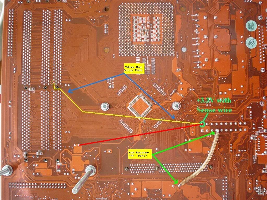
There is a Vdd mod here.
The Vdd booster is supposed to help stabalise the Vdd voltage, but I don't think many people have found much benefit from doing the mod.
mine wont even post with the VDD booster.
All along the watchtower the watchmen watch the eternal return.
Hey i tried you mod STEvil it didnt work for me. No differnce in voltage. Which i find odd. Does it matter that my board is a plain NF-7? The punk method does however work, But unregulated voltage and fluctiuations under load isnt appealing to me. Thanks for all your help man. This means another log on the fire
Mine is also a plain nF7.
Mine and Dirty Punk's mods are 100% exactly the same except mine has higher current carrying capacity. Thats it.
All along the watchtower the watchmen watch the eternal return.

Ummm can you take measurements showing the vref tracks without vtt=vref? I always remember needing it...
Already did.
All along the watchtower the watchmen watch the eternal return.
Pin1 - Vref
Pin2 - Vtt
Pin7 - Vdimm
Tracks quite nicely, If you ask me
EDIT: I just noticed that STEvil is talking about different way of doing VIO=VDIMM mod... Those photos above are taken with the NF7-S with "Dirty Punk's method".
Last edited by bachus_anonym; 04-01-2005 at 05:56 PM.
Wow I've learned alot reading this thread.
Got a new NF7-S rev2 now (killed my other one, which was too bad considering the thought that it did 260fsb+) and when I start modding it for real I'll try your method STEvil instead of the Dirty Punk method.
I've just got one question, when done the Dirty Punk vio=vdimm does all of the dimm ports recieve 3,3V or just the first one? My belief is that all of the ports get 3,3V but a guy over at a Swedish forum made me wonder. It would explain why my card did a bit over 260fsb with the ordinary vdimm mod and about 250 with the dirty punk mod.
Thnx all
AMD Turion MT34 @ 250*9=2250MHz 24/7
ATI X800PRO
MSI K8NM FISR BIOS Rev 1.5 My first BIOS modification
2x80GB Maxtor drives @ RAID-0
1x160GB Seagate
Everything in a mATX case.
Yep, all DIMM slots are getting same volts when using VIO-VDIMM mod and one wire
Hi,
I did THIS mod for my nf7-s Pict1 Pict2 and I started my pc, opened bıos, then ı set 200x8 to test for first time(ı used 3 switches for turning them on-off; i tried this settings while mods closed). I saved and reboot pc but it didn't opened again
I checked mods hundered times and all of them were set correctly,ı used silicone to protect them as well... What's wrong in this situation? Please help me
My system;
Abit nf7-s
xp 1.8+
2x512 a-data vitesta 500 mhz ddr
Gas cooling Cpu&Nb (-50&-30 on the gasblock)
Last edited by Antiloop; 04-03-2005 at 03:29 PM.
Get rid of vtt=vref mod... It's not needed when vio=vdimm mod is done and can actually mess with your board if you have vdimm mod done above mentioned way. It's only necessary when "normal" vdimm mode is done.
Do that and report back, please.
The wire you used for the VDIMM=VIO is too small and too long, and the point it is connected to is not designed to carry high amperage.
The vdd booster mod doesnt work for me either, system will not post with it connected.
All along the watchtower the watchmen watch the eternal return.
exactly, like STEvil says.
in other words, just leave vio=vdimm mod in place. the other two mods really do not help at all... just make things worse most of the time.
Hi everyone;
bachus_anonym and STEvil,today evening I got rid of all mods and I applied vio=vdimm with better wire; then ı connected gascooling and started my pc but it didn't work. I cut all of the wires however it didn't work....


So, with no-mods it doesn't even POST anymore ? Damn bad news if so...
See if there's nothing shorted on the board. Check voltages...
 Posting Permissions


 Reply With Quote
Bookmarks