MMM
Results 1 to 22 of 22

Thread: Asus P5P800 vDimm mod help

  1. #1
    Xtreme Member
    Join Date
    Feb 2004
    Location
    Denmark
    Posts
    241

    Asus P5P800 vDimm mod help

    There is currently only one vDimm mod available for Asus P5P800 wich is connecting the 3,3v rail to the vDimm so the vDimm turns into 3,3v. Correct me if I'm wrong, but the voltage will be 3,3v when having default vDimm setting in bios. Upping the vDimm in bios to 2,7v (+0,2v) would give a effective vDimm of 3,5v?

    Then would it be possible to make a fly-back circuit with the 3,3v as source supplying 3,1v to the points on the motherboard where the 3,3v was directly connected. That should give a vDimm interval of 3,1-3,45v... another idea of this mod would be to make a switch on the wire going to one of the points on the motherboard so it would be possible to turn the mod on and off...

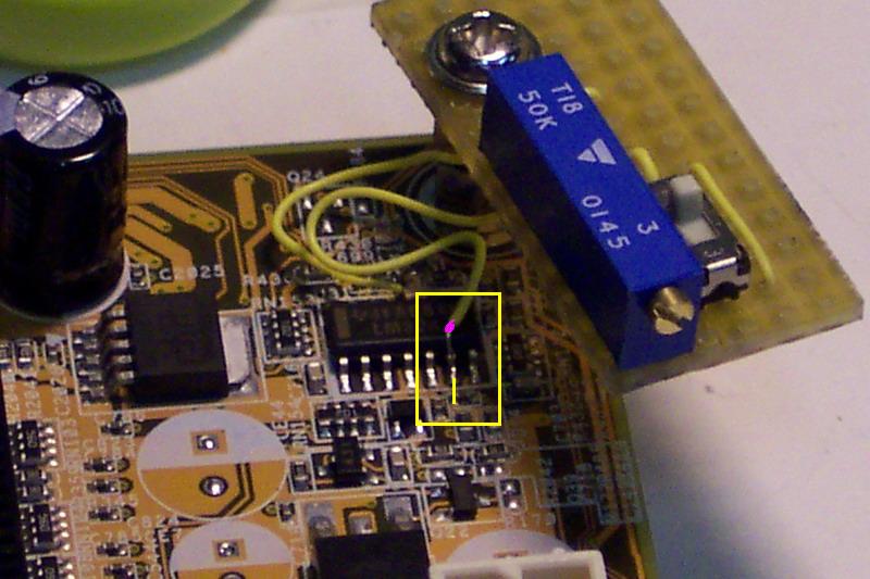
    Picture of the vDimm mod: http://pienari.is-mad.com/Pics/Asus_..._V-mem_mod.JPG
    Picture of all of them: http://pienari.is-mad.com/Pics/Asus_p5p800/
    P5P800 Vmod thread: http://xtremesystems.org/forums/show...t=42646&page=1

    I'll try illustrate my idea in paint... maybe another soloution is possible
    Attached Thumbnails Attached Thumbnails Click image for larger version. 

Name:	vdimmp5p800.jpg 
Views:	1904 
Size:	25.7 KB 
ID:	20720  
    Last edited by Salkcin; 12-08-2004 at 02:43 PM. Reason: Attached image

  2. #2
    Xtreme Mentor
    Join Date
    May 2003
    Location
    Engineering Lab - NCSU
    Posts
    2,978
    I cant imagine that using the 3.3v rail is the only option for a Vdimm mod on this board.

    Just so you know, once you use the 3.3v rail for a Vdimm mod you do not have the capacity to make any adjustments via the bios. Whatever you 3.3v rail is sitting it is what your Vdimm will be...well, minus a couple of tenths maybe. So, if your rail is at 3.6v, then your Vdimm will be 3.35-3.5v or so. And the only way to adjust it once you do this type of mod is by using a high watt resistor on the wire connecting the 3.3v rail to the mod location.

    I will look over those pics and will need some things answered from you bud.

    **EDIT**
    Please answer the questions on the pic.
    Attached Thumbnails Attached Thumbnails Click image for larger version. 

Name:	P5P800.JPG 
Views:	1896 
Size:	94.5 KB 
ID:	20721  
    Last edited by Hell-Fire; 12-08-2004 at 02:43 PM.


    I like my women the way I like my processors...naked.
    I am not the HellFire that writes bios files. I work strictly on voltage modifications.

  3. #3
    Xtreme Member
    Join Date
    Feb 2004
    Location
    Denmark
    Posts
    241
    Okay - idea killed already, but looking at my picture do you think a mod that does the same as I ilustrated would be possible? Forget the voltage regulating thing and so - think of the functionallity of the final product should have been

    I can supply you with high quality close up pictures of the board if needed

    EDIT: Lying on the floor reading out the chips now. Damn some of them got long "names"
    Last edited by Salkcin; 12-08-2004 at 02:52 PM.

  4. #4
    Xtreme Mentor
    Join Date
    May 2003
    Location
    Engineering Lab - NCSU
    Posts
    2,978
    Yes, I would like high res pics of the area around the dimms. Include a few inches on each side of the dimms so I can see the chips. And please point out where the Vdimm is read. Figure its off one of those mosfets on the left of the dimms in my pic.

    I need close ups of the chips as well, but not so close up that I cant see the surrounding area.

    Yes, a switch will certainly work, but it needs to be a high current switch.


    I like my women the way I like my processors...naked.
    I am not the HellFire that writes bios files. I work strictly on voltage modifications.

  5. #5
    Xtreme Member
    Join Date
    Feb 2004
    Location
    Denmark
    Posts
    241
    Here are they. Desciptions made compared to the picture. The "-" means the text was placed in a new line

    The one in the left: 42ARN1K - LM324

    In the rigth middle: MV358I - 41M - CJY9
    In the lower rigth: G075232 - 45K - A3IV (G0752... could the 0 be the letter or number. I don't know)

    Hope you can use any of this... the one in the upper right is VERY difficult to read (when the mobo's in case and in use ). I can take some reading it out if you like?

  6. #6
    Xtreme Member
    Join Date
    Feb 2004
    Location
    Denmark
    Posts
    241
    I'm not taking those pictures now since it would require me to take out the motherboard and it's 12.16 AM in Denmark (bed time soon). I proberly take them tomorrow if I can find some time (I proberly do!).

    Thanks for your interest of helping

  7. #7
    Xtreme Member
    Join Date
    Feb 2004
    Location
    Denmark
    Posts
    241
    By the way... I have no idea where to measure the vDimm. Proberly on some of the mosfets below the vDimms or am I wrong?

  8. #8
    Xtreme Mentor
    Join Date
    May 2003
    Location
    Engineering Lab - NCSU
    Posts
    2,978
    Quote Originally Posted by Salkcin
    By the way... I have no idea where to measure the vDimm. Proberly on some of the mosfets below the vDimms or am I wrong?
    Check here.
    Attached Thumbnails Attached Thumbnails Click image for larger version. 

Name:	Vdimm_Read.JPG 
Views:	1884 
Size:	61.7 KB 
ID:	20723  


    I like my women the way I like my processors...naked.
    I am not the HellFire that writes bios files. I work strictly on voltage modifications.

  9. #9
    Xtreme Member
    Join Date
    Feb 2004
    Location
    Denmark
    Posts
    241
    What leg to measure? allways the one in the middle?

    EDIT: Could'nt wait for an answer. Figured out nothing could go wrong (or...? :P). Anyways. The voltage is set at 2,85v in bios and measured from the left (or from up to down in the picture) the mosfets give 2,5v - 2,6v and 2,7v. It should be mentioned that I'm using a analog multimeter. If it makes any sense the mosfet next to the AGP slot was measered 2,6v and just over the AGP slot on the right the vAGP is measered
    Last edited by Salkcin; 12-08-2004 at 03:38 PM.

  10. #10
    Xtreme Mentor
    Join Date
    May 2003
    Location
    Engineering Lab - NCSU
    Posts
    2,978
    You should be reading the voltage from the legs that are soldered to the board.


    I like my women the way I like my processors...naked.
    I am not the HellFire that writes bios files. I work strictly on voltage modifications.

  11. #11
    Xtreme Member
    Join Date
    Feb 2004
    Location
    Denmark
    Posts
    241
    okay... did some more measuring and found out the varying results are because of I did'nt held the multimeter straigth horizontal :P... there's measured 2,6v on all of the mosfets middle leg at both vDimm 2,55v and 2,85v. And the mosfet i mentioned was'nt vAGP. All my mistakes...

    anyway. Could there happen any bad thing if shortening the wrong leg to ground on the mosfets? As I can understand I shall measure on the right OR left leg.

  12. #12
    Xtreme Member
    Join Date
    Feb 2004
    Location
    Denmark
    Posts
    241
    HAHA - I end up destroying something by doing before getting an answer :P

    I found out that the one placed highest in the picture is the one you measure on (the highest leg to - seen normally it's the mosfet on the left and the leg on the lef of it to measure on).
    Last edited by Salkcin; 12-09-2004 at 05:18 AM. Reason: Image deleted from the host

  13. #13
    Xtreme Hardware Killer
    Join Date
    Jan 2004
    Location
    Behind you
    Posts
    1,265
    I'll place money on it that the LM324 is the one.
    Level 80 UD Death Knight on Murmur (Beta)

  14. #14
    Xtreme Mentor
    Join Date
    May 2003
    Location
    Engineering Lab - NCSU
    Posts
    2,978
    I agree with bh2k.

    But without a better pic, its gonna be trial and error big time. THe LM324 has 4 error amplifiers in it if I recall. I want to say pin #6 to ground, but cant be certain. It is the closest error amp pin to the fet reading Vdimm, but that doesnt mean a thing frankly. Can you give me a resistance between pin #6 and ground..with the board powered down and the psu turned off.


    I like my women the way I like my processors...naked.
    I am not the HellFire that writes bios files. I work strictly on voltage modifications.

  15. #15
    Xtreme Member
    Join Date
    Feb 2004
    Location
    Denmark
    Posts
    241
    *** deleted text - new measurements ***

    Another thing - you said I would need a high current switch to make a switch for the mod. Thinking of the wires used when modding they are very thin and should not be able to take many amps... why need a switch that will be able to handle "many" amps when in same circuit?.

    EDIT: I'm going to link this image - it would kill the thread because of the size . 2048x1536 - hope it's good enough. Ignore all the dirt - thinks it's from the time I bathed the motherboard in all the water from the watercooling

    Image: http://users.cybercity.dk/~dsl30381/lm324highres.jpg

    2nd EDIT: It's hard to track down the traces from any of theese pins to the left leg on the left mosfet. I have a connectivity tester, but would it damage anything? think it's using 9v to test for connectivity (but not sure). I'm by the way going to remeasure with a digital multimeter I'm going to borrow later.

    3rd EDIT: Updated the attachment so it fits the reply below
    Attached Thumbnails Attached Thumbnails Click image for larger version. 

Name:	p5p800-mod.jpg 
Views:	2682 
Size:	173.1 KB 
ID:	20750  
    Last edited by Salkcin; 12-09-2004 at 11:50 AM. Reason: Took high resoloution picture of the LM324

  16. #16
    Xtreme Member
    Join Date
    Feb 2004
    Location
    Denmark
    Posts
    241
    Okay - I got the things remeasured with a digital multimeter. The mosfet is measured 2,87v when vdimm is set 2,85v and 2,59v when it's set 2,55v. I'll accept that as the right one (other mosfets where measured 3-3,1v and 12v).

    I measured two diffrent pins on the LM324 - pin #6 counted from left to rigth compared to the picture on the upper side and downside of the chip. The one in the upper row was measured 1037 Ohm and the one on the downside was measured 992 Ohm. I don't know why this measurement was so diffrent from the analog, but I trust the digital the most!

    All the voltages was measured with the black wire in the 4-pin molex connector as ground.

  17. #17
    Xtreme Mentor
    Join Date
    May 2003
    Location
    Engineering Lab - NCSU
    Posts
    2,978
    Ok bud...thanks for the readings. Thats definitely the Vdimm fet.

    And just to be certain, that resistance reading of 1037 ohms is on pin #9 correct? If so, you can try the mod I suggest below.

    One thing to try first. Check the voltage at the spots I marked. Pins #9 and #13 are the most likely candidates for the mod, but we cant rule out the pins on the other side LM324 until we know for sure of course. If you want, post your readings on the voltages at those pins before doing the mod below.

    Try a 10K vr between pin #9 and Ground. Figure we will start at pin #9 since that side of the chip is facing the Vdimm FET...and go from there. Be sure its set to max resistance before soldering it on there of course. And be sure to check the Vdimm as you are adjusting the VR. Best to solder a wire to that FET leg so you can just have the multimeter showing the voltage as you turn the vr's screw.
    Attached Thumbnails Attached Thumbnails Click image for larger version. 

Name:	VdimmCheck.JPG 
Views:	1875 
Size:	112.4 KB 
ID:	20756  
    Last edited by Hell-Fire; 12-09-2004 at 04:15 PM.


    I like my women the way I like my processors...naked.
    I am not the HellFire that writes bios files. I work strictly on voltage modifications.

  18. #18
    Xtreme Member
    Join Date
    Feb 2004
    Location
    Denmark
    Posts
    241
    Hi again.

    It should be pin #9 since the pin measuered 1037 Ohm is the cloesest one to the vdimm mosfet. I have a question about the components. I'm going to use normal components - no high precision multi-turn VR's or ½watt low tolerant resistor. It's a 27kOhm 5% tolerant 0,25watt resistor wich is going to be serial connected with a 2,2kOhm VR adjusted for 28kOhm so I can make the vDroop as well. The vDimm I'm going to try is just a regular 10kOhm variable resistor, but the voltage should'nt be rising 0,9v (where it gets dangerous) before I'm going to notice. I will of course turn the variable resistor gently

    I have a question about the attachment you made. Why should I connect a pin in each cornor to the nearest condesator (I think it is)? What good is it and should this be done along with the 10kOhm VR on pin #9 to ground (where is the nearest ground? please inform )

    I'm planning to do the mod when I'm going to change my waterblock since I anyway would need to unmount the motherboard. Can't tell when it is - tomorrow is planned, but seems I can't get the rigth fttings for the waterblock till tomorrow. On tuesday in worstcase.
    Last edited by Salkcin; 12-10-2004 at 10:12 AM.

  19. #19
    Xtreme Mentor
    Join Date
    May 2003
    Location
    Engineering Lab - NCSU
    Posts
    2,978
    As far as nearest ground, you will ahve to determine that on your own. You can use a screw hole, or pin #11 on LM324 as ground.

    As for the things I pointed out in the pic, those are just places I wanted someone to give voltage readings for. Keep in mind that you should check that the mod works for pin #9 before remounting the board. I dont know if it will work or not until someone tries it, or atleast gives me voltage readings on the 4 places I circled.


    I like my women the way I like my processors...naked.
    I am not the HellFire that writes bios files. I work strictly on voltage modifications.

  20. #20
    Xtreme Member
    Join Date
    Feb 2004
    Location
    Denmark
    Posts
    241
    Look at the attachment for the readings...

    Maybe it sounds stupid, but how should I be able to test the board before re-mounting it to the case? - don't you just mean I should power up the system on my desk before having all the trouble mounting it again?

    I got the parts ready for the mod, but then I found out I borrowed my soldertool to a friend. Will go get it later in case I get possitive answers from you

    EDIT: Don't know if it's a relevant infomation, but the vDimm was set 2,85v at the time of the measurement.
    Attached Thumbnails Attached Thumbnails Click image for larger version. 

Name:	lm324mes.jpg 
Views:	1797 
Size:	196.6 KB 
ID:	20808  

  21. #21
    Registered User
    Join Date
    Dec 2003
    Location
    Rome Italy
    Posts
    86
    LM324 single supply quad operational amplifier fairchild , it's same at asus a8v 939 , and the vmod is same for me, pin 6 and pin 11

    someone confirmation?

    best regards

    wasky

    http://www.xtremesystems.org/forums/...ad.php?t=37075

    LM324


    and this is a my mod on asus a8v 939,


    Last edited by wasky; 03-07-2005 at 02:53 AM.

  22. #22
    Registered User
    Join Date
    Dec 2003
    Location
    Rome Italy
    Posts
    86
    up please

    10x and best regard

Bookmarks

Bookmarks

Posting Permissions

  • You may not post new threads
  • You may not post replies
  • You may not post attachments
  • You may not edit your posts
  •