


Hello!
Finaly I am able to show you better pictures.
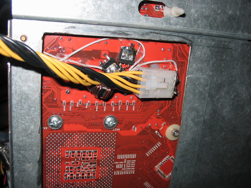
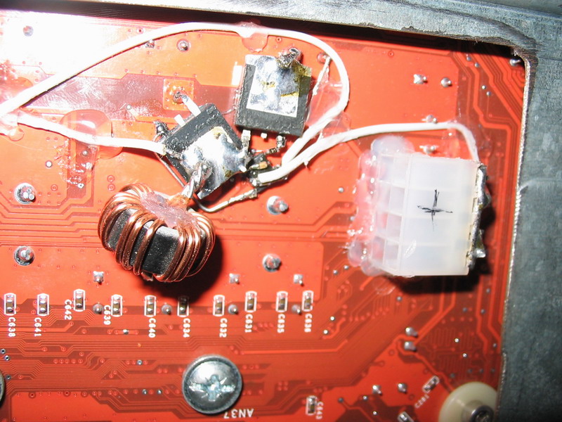
Now you can see details, but the problem is because everything is so small and messy. I had to improvise. Those two wires that go on the front side of the board are PWM signal and Isen sense line for fourth phase. Chip wich controls MOSFETs is located between MOSFETs, where all the wires go. Also there are a few small SMD capacitors and resistors soldered directly between legs of that chip... as I said before It is a mess. But it is working. So far...
As you can probably see from the pictures above I've soldered aditional 8 pin ATX_12V connector to my board, so I can use both ATX_12V supply lines on my Tagan PSU. It decreases voltage drop across cables for 20mV...
Thats it.
Thanks for warning me, but I am aware of that problem, I am studying elecronics engineering and I know quite a lot about PWM voltage regulators.Be careful as raising switching frequency will also play a HUGE role in the losses of the upper MOSFET...i.e. it will get a lot hotter.


 Reply With Quote


Bookmarks