


Lets start off with introductions. I'm a retired Professional Overclocker who had/still has a No thrills No bullapproach to any hardware I work on. Reviews for overclockers by an overclocker.
Some may remember me some may not. Some may like or dislike my tough love approach but to bad, you don't have to read it.
Onto the board in question. Z490i Meg Unify. Retail board purchased at a microcenter like any other end user can. No pictures from me as the enclosure/build it's in is currently NDA so I will use pictures off MSI's site.
I've taken the liberty to point out the only items that 90% of users will need concern themselves with. As you can see the power/reset etc is located in a rather less than optimal location Other than that no complaints. If you were bench testing on a bench station with this board your definitely going to want to carnage power/reset buttons from a case lest your screwdriver slips and you ground out on your VGA. No RGB thank god......still has headers though.
When I saw a teardown of this board and seen a small fan blows at a heatpipe I was like well that looks useless. I was right. They should have put more USB ports on the back panel and beefed up heatsink enough to passively cool better.
If you want detailed vrm analysis and specs I suggest watching buildzoids video but the summary is the vrm is fine both on paper and in real world.
The heatsinks and heatpipe/vrm fan implementation is not so great however and even a low 800-1200 rpm fan blowing in the general direction of it is more than effective to keep things cool enough that the mosfet fan never even turns on.
This also applies to the southbridge heatsink/SSD heatsink as that can get quite toasty with little to no airflow. Just make sure your case has some airflow and if not add a fan so it does.
Passive
Fan
Voltages and extreme overclocking features or the lack there of.
No Ln2 jumper on board that I can identify.
No vtt voltage adjustments.
Limited vcore (1.7v range IIRC)
This is where you ask yourself questions like what is MSI is trying to do with this board? They have a 10 layer PCB, surface mount dimm slots, optimized trace layout and no vtt voltage control or monitoring for that matter.
I can get the limited voltage no ln2 mode jumper as a 10900k on ln2 could potentially push this vrm and 8 pin a tad to far but I don't get the reasoning behind going all out on the memory layout and excluding vtt voltage/monitors.
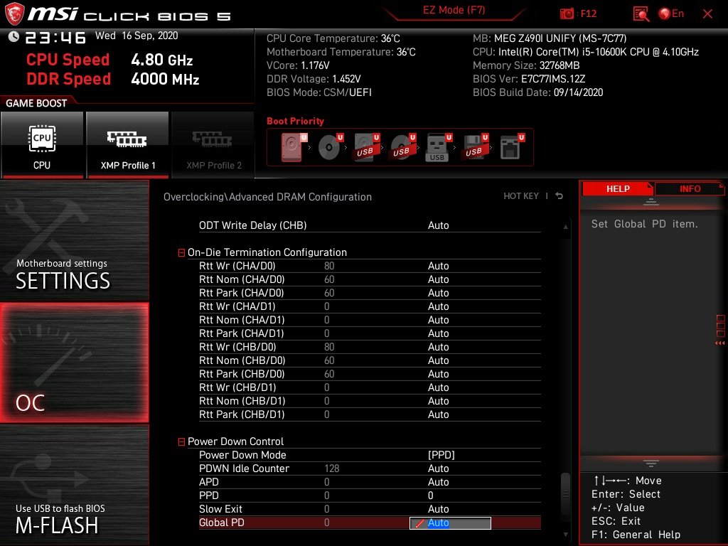
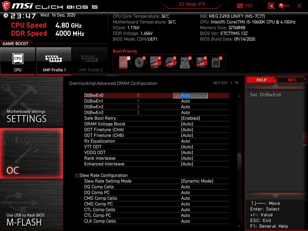
Default LLC on board is a tad overkill. 1.175vcore manually set will net you roughly 1.2v peak under prime 95 load. I suggest adjusting llc so you have a little vdroop which will lower power consumption and temps. This is probably why some youtubers were failing to match overclocks on this board compared to others. I had no problem hitting 5.1 on a 10600k.
Test config.
10600k
Custom Asetek AIO ( cpu is cooling limited not board limited )
2x16gb gskill Neo 3600 c16 Bdie
MSI Meg Unify I z490
Corsair SFX 750
Reference 2080TI
Samsung 970 Evo + 2tb
Stability wise no complaints even cpu cooling limited it should be easy to dial in a memory OC with cpu Oc to 4.8 with a -1 avx offset.
I don't put much stock in XTU as the end all stability test but since another vendors ITX board I tested refused to pass avx 512 for 5 minutes with anything resembling memory tuning I ran it anyway.
I don't put much stock in Aida for a stability test but some people I deal with do so I ran that to.
I do trust prime and since so many are "afraid" to run it I trust it even more
HCI is another one I trust IF and this is a big IF you overkill the task scope.
Apparently the new craze is TM5 with anta777 extreme so I ran that off while I was writing this with slightly some modified tighter timings as I'm still fine tuning.
This is my personal favorite stability test which I call thrash the system. I usually let it cook for a 12 hour minimum.
3d results on the board are good. Nothing out of the ordinary and everything is inline with what I would expect. I did not bother with results.
Lets go back to the topic of memory as that is where we find some things that are not quite inline with what I would expect.
One of the things I noticed is the RTL IO-L and the rtls in general just don't pull in quite like I would expect them to. In fact if you go to tight the board posts fine and sets them extremely loose.
The side effect at least from what I have experienced is latency performance is poor as a result.
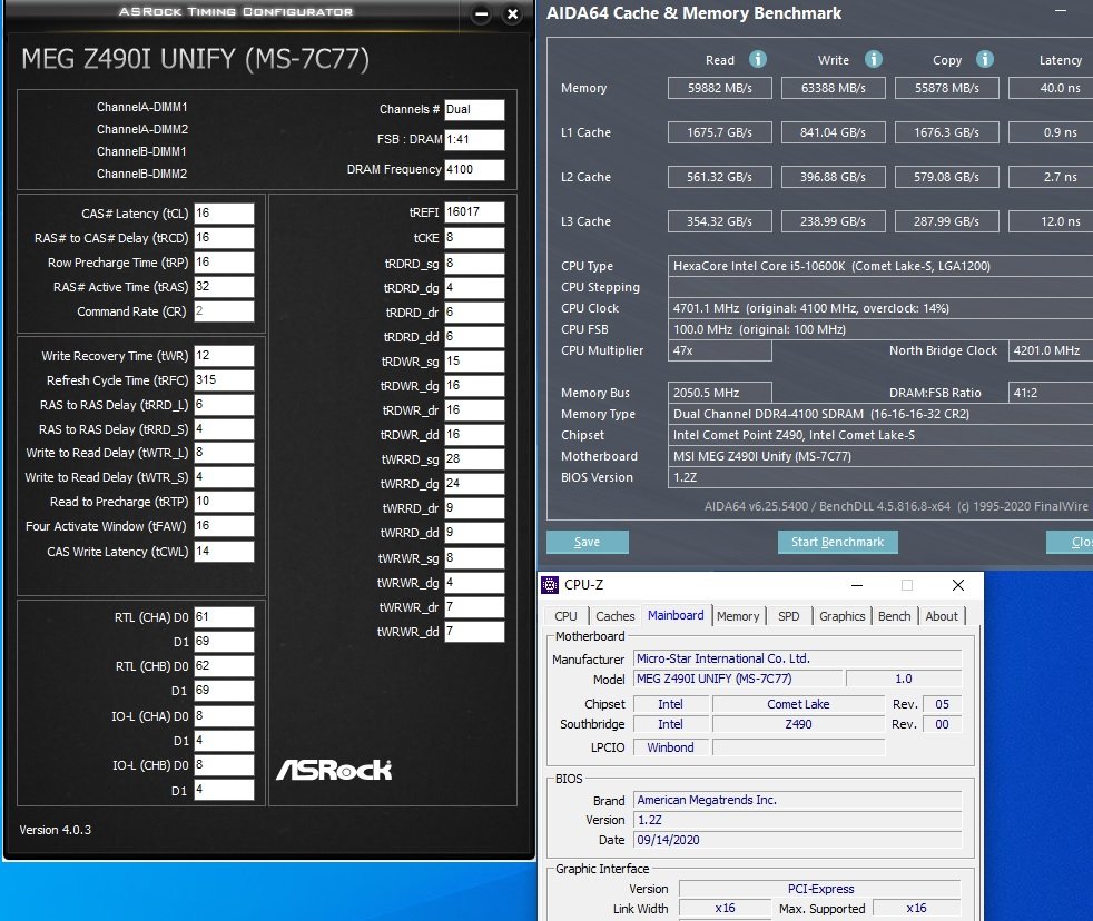
Here's an example keep in mind this is 2x16gb so the memory clock speeds are on par with what I expected.
The board can run c14 2000 as well although I did not test as to what kind of volts that would require nor if it was even possible to get stable.
Going beyond 2000 seems to pose a problem with at least this particular config. I'll call c14 2000 2x16gb "bench stable"
2000 c16 2x16gb bdie should be a realistic goal with 1.45v dimm. What it can't seem to do is produce latency results that one would expect at these timings and speeds.
Conclusion.
I don't draw conclusions. I present data. You draw your own conclusion.
I draw an educated opinion and having worked with the board my opinion is the board has Identity crisis. It does not know if it wants to be a 2 dimm memory overclocking performance champ or not. I'm sure that the latency issue will get worked out via a bios update but i'm not 100% sure that they can give us full vtt control and monitors at which point anyone looking for a relatively affordable memory overclocking board is going to have to whip out a soldering iron void warranty and volt mod this board to get the required volts needed to play the xtreme memory overclock game.
I mentioned 2000 was a realistic goal so I verified it. It's baseline and can be tweaked from here. I included timings. Voltages required are included in hwinfo and accurate however I suggest tuning your vccio/vccsa to your chip not mine.


 Reply With Quote


Bookmarks