Page 10 of 17 FirstFirst ... 78910111213 ... LastLast
Results 226 to 250 of 423

Thread: ABIT IC7 – IC7-G – IC7 MAX3 ALL in one Modifications - The way to go!

  1. #226
    Xtreme Member
    Join Date
    Jun 2004
    Posts
    257
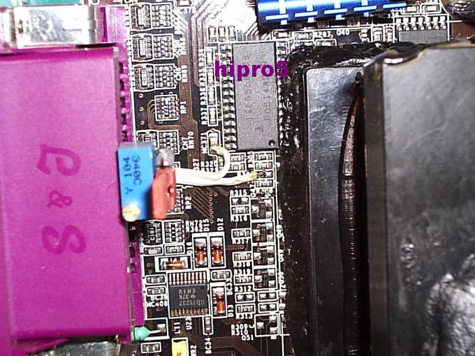
    Just done some more thorough checking - the AGP regulator mosfets are not powered by it....the PLL definately is, VDD and VDDA on the ICS952607 are connected direct to that mosfet output where that 5v mod is) and is definately burning up when at 5v - well beyond its 3.3v rating.

    Im not 100% certain about the southbridge, but it was getting hot very quick (more so than normal) when i booted the board with no cpu or ram installed (to test and measure voltages).

    Its also possible certain lines to the northbridge are coming from that mosfet output.

  2. #227
    k|ngp|n/Sham my brothers
    Join Date
    Aug 2002
    Location
    Athens---Hellas
    Posts
    5,693
    I'm working with the 5Volts mod over a week and so and I haven't got any problems yet.....Anyways I'll take a look of it as soon as I can......
    INTEL PWA FOR EVER

    Dr. Who my arss...

    .........


  3. #228
    Xtreme Legend
    Join Date
    Nov 2002
    Location
    Sweden
    Posts
    1,019
    Originally posted by froudeg
    the only safe way to do this mod is as above and disconnect both vddr mosfets from that 3.3vDual source and connect em direct to 5v.'
    Can you give us a hint about how hard these bastards are to get of the board?

    What about vtt tracking? Is the normal vtt mod able to handle, say 1.9vtt? (yes, 3.8vdimm)

    "In mild doses, ethylene produces states of euphoria, associated with stimulus
    to the pleasure centres of the human brain."

    Intel benching: 3DMark Vantage: E69642, P37253, H30363, X22138
    Swedish Overclocking Champion 2006 - Celeron Mobile 1400 @ 4243MHz - 203%

  4. #229
    Xtreme Member
    Join Date
    Jun 2004
    Posts
    257
    VTT doesnt have a problem - since it has plenty of headroom with the 3.3v rail.

    To get those mosfets off, you will need to use a large chisel tip on your soldering iron (bigger contact area on the metal tab).....it helps if you have got an adjustable soldering station, but it is possible to remove them with a 25 watt soldering iron - altho i recommend something thats 40 watts.

    Put the tip on the tab, apply some solder until it flows along the metal tab, then with a small precicion screwdriver try to prise it up - its tricky as you need to keep the iron on it as you do this.

    It maybe easier just to toally desolder it (desolder the 2 legs 1st) etc then just solder those 2 legs back on when ya removed it.

  5. #230
    Xtreme Legend
    Join Date
    Nov 2002
    Location
    Sweden
    Posts
    1,019
    I really need a dedicated benching board to try all these cool things!

    "In mild doses, ethylene produces states of euphoria, associated with stimulus
    to the pleasure centres of the human brain."

    Intel benching: 3DMark Vantage: E69642, P37253, H30363, X22138
    Swedish Overclocking Champion 2006 - Celeron Mobile 1400 @ 4243MHz - 203%

  6. #231
    Registered User
    Join Date
    Nov 2003
    Location
    wash dc area
    Posts
    40
    i was able to replace my vtt mosfet with a 30 watt iron i left the legs atached heated metal tab and lifted with a small screwdriver.the attached legs keep it from flying all over the place

  7. #232
    Xtreme Addict
    Join Date
    Aug 2003
    Location
    Buenos Aires, Argentina
    Posts
    1,603
    Originally posted by hipro5
    I'm working with the 5Volts mod over a week and so and I haven't got any problems yet.....Anyways I'll take a look of it as soon as I can......
    Could you please post some more pics or update our Bible, err, sorry your Guide
    Where do I need to solder that fat cable? I did the mod like in your guide but I'm not able to put more than 3.38V in my bh5's
    BTW, my board is an IC7

  8. #233
    Xtreme Member
    Join Date
    Jun 2004
    Posts
    257
    I recommend ppl dont perform the 5v mod for now until hipro has finished checking it.

    As i say the PLL chip is definately getting 5v when the mod is performed in this way, and its only rated for 3.3v....it gets scorching hot and i believe it will burn out - it may take a few weeks but i do think it will burn out for ppl who are doing more than just the odd bench - ie. ppl who intend to perform this mod on their main pc.

  9. #234
    Xtreme Member
    Join Date
    Jun 2004
    Posts
    257
    Check this out, have a guess what it is


  10. #235
    Xtreme Legend
    Join Date
    Nov 2003
    Location
    Helsinki, Finland
    Posts
    1,692


    It only takes 3.4V to reach 265FSB with these KHX3200 BH-5 sticks

  11. #236
    k|ngp|n/Sham my brothers
    Join Date
    Aug 2002
    Location
    Athens---Hellas
    Posts
    5,693
    Yes.......The PLL chip gets 5V from the Rams IF you mod your mobo with the 5V mod......Not the Southbridge.....PLL chip gets hot but with a heatsink on it you can make it.....

    For real now.......I would suggest ppl not to do the 5V mod IF they don't have heatsinks on their Mos-Fets and on the PLL chip.........After all.......That's XTREME......
    INTEL PWA FOR EVER

    Dr. Who my arss...

    .........


  12. #237
    k|ngp|n/Sham my brothers
    Join Date
    Aug 2002
    Location
    Athens---Hellas
    Posts
    5,693
    Originally posted by The Stilt
    It only takes 3.4V to reach 265FSB with these KHX3200 BH-5 sticks
    You are lucky and GOOD with those Rams of yours M8.......They're doing grate........
    INTEL PWA FOR EVER

    Dr. Who my arss...

    .........


  13. #238
    Xtreme Member
    Join Date
    Jun 2004
    Posts
    257
    Yep Hipro - my mosfets got scorching, and it became unstable unless i had a good fan blowing on them.

    I decided to hell with that crap linear regulator on the motherboard and am now using that switching regulator i cut out from a kG7 - its working really well!, got more overclock, and the board doesnt even get warm.

  14. #239
    Registered User
    Join Date
    Nov 2003
    Location
    wash dc area
    Posts
    40
    Originally posted by froudeg
    Yep Hipro - my mosfets got scorching, and it became unstable unless i had a good fan blowing on them.

    I decided to hell with that crap linear regulator on the motherboard and am now using that switching regulator i cut out from a kG7 - its working really well!, got more overclock, and the board doesnt even get warm.
    jesus, what are u and hipro? engineers or electronic techs???i wish the hell id have gotten more electronics backround instead of fiber optics. u two are MANIACS....

  15. #240
    k|ngp|n/Sham my brothers
    Join Date
    Aug 2002
    Location
    Athens---Hellas
    Posts
    5,693
    Originally posted by froudeg
    Yep Hipro - my mosfets got scorching, and it became unstable unless i had a good fan blowing on them.

    I decided to hell with that crap linear regulator on the motherboard and am now using that switching regulator i cut out from a kG7 - its working really well!, got more overclock, and the board doesnt even get warm.
    That's clever..........
    INTEL PWA FOR EVER

    Dr. Who my arss...

    .........


  16. #241
    Xtreme Legend
    Join Date
    Nov 2002
    Location
    Sweden
    Posts
    1,019
    Originally posted by froudeg
    Check this out, have a guess what it is


    More info!

    EDIT: I've found out that you've got more images of that mod
    Last edited by crotale; 07-25-2004 at 02:29 AM.

    "In mild doses, ethylene produces states of euphoria, associated with stimulus
    to the pleasure centres of the human brain."

    Intel benching: 3DMark Vantage: E69642, P37253, H30363, X22138
    Swedish Overclocking Champion 2006 - Celeron Mobile 1400 @ 4243MHz - 203%

  17. #242
    Xtreme Member
    Join Date
    Nov 2003
    Location
    Germany Berlin
    Posts
    131
    thanks hipro for ur help with the vtt mod. judt got it working and i just need some more conductive paste cput temp is really bad with 50 C under full lod at stock volts and 3,5ghz . hope that vtt mods helps my 5:4 issue
    2,8€ @4130mhz
    radeon 98 pro440/380
    ic-7max3 full modded

  18. #243
    k|ngp|n/Sham my brothers
    Join Date
    Aug 2002
    Location
    Athens---Hellas
    Posts
    5,693
    U P D A T E


    In case that someone needs the VCore mod.......Here it is.......

    Just solder a 100 KOhms trimer at this spot to ground......


    GROUND is the one side of the MC371 where one cable is soldered and the other spot is the THIRD spot from the IC and to com and serial ports side (not the CPU side) of the mobo......There's a missing resistor there....
    Last edited by hipro5; 09-17-2004 at 02:07 AM.
    INTEL PWA FOR EVER

    Dr. Who my arss...

    .........


  19. #244
    Xtreme Enthusiast
    Join Date
    Aug 2004
    Location
    Brasil, S.P.
    Posts
    999
    Where can I measure the vcore?
    990FXA-UD3 | FX8350@4.7Ghz | Asus HD7870 | 2x 4GB Crucial Ballistix Tracer 2050Mhz 8-8-8-22 | AX850W |SSD Vertex3 Max IOPS 120GB | Auzentech Forte + TAPCO-S5

    EK Supreme Full-Gold | XSPC RX240 + EX120 | MCP35x | 3x Koolance Blue Led @PWM | Tygon Black 1/2 | Bitspower Compression | @ FM CM690 I

  20. #245
    k|ngp|n/Sham my brothers
    Join Date
    Aug 2002
    Location
    Athens---Hellas
    Posts
    5,693
    You can measure in on the sides of the big rounded coils near CPU socket....NOT on them coz they are covered with some sort of varnish....On their sides.....
    INTEL PWA FOR EVER

    Dr. Who my arss...

    .........


  21. #246
    Xtreme Legend
    Join Date
    Nov 2003
    Location
    Helsinki, Finland
    Posts
    1,692
    hipro5, how big increasements in fsb is possible to archieve when ex. 156W peltier (with cold water) is applied to nb?

    I´m going to pelt this crappy AS8, which currently can´t run much over 250FSB 1:1, eventhou the VTT is working as it should

    Other solution could be increase of VAGP voltage like in IC7 series. Maybe I should figure it out some day, because the board uses exactly same chip as IC7 boards

  22. #247
    k|ngp|n/Sham my brothers
    Join Date
    Aug 2002
    Location
    Athens---Hellas
    Posts
    5,693
    Quote Originally Posted by The Stilt
    hipro5, how big increasements in fsb is possible to archieve when ex. 156W peltier (with cold water) is applied to nb?

    I´m going to pelt this crappy AS8, which currently can´t run much over 250FSB 1:1, eventhou the VTT is working as it should

    Other solution could be increase of VAGP voltage like in IC7 series. Maybe I should figure it out some day, because the board uses exactly same chip as IC7 boards

    At -30*C with a Vapo , I gained 3 MHz at max fsb and about 1 - 2 MHz at 1:1 configuration.........The secret though to play with 1:1 is to uper the VAGP up to 1.98Volts(at 2VAGP mobo's shuting down from OVP).....I think you'll gain another 5MHz or so......
    INTEL PWA FOR EVER

    Dr. Who my arss...

    .........


  23. #248
    Xtreme Enthusiast
    Join Date
    Aug 2004
    Location
    Brasil, S.P.
    Posts
    999
    Quote Originally Posted by hipro5
    You can measure in on the sides of the big rounded coils near CPU socket....NOT on them coz they are covered with some sort of varnish....On their sides.....
    That's pretty bizarre I tough I was using 1.56V and I found out that it was actually between 1.57~1.62V Is it alright? How can I reduce that oscilation?


    Now I've got VDD, VTT, VDIMM and eletrolitic Capacitor.

    What voltage I gonna get if a set the 50k trimmer to 0 in the VDD mod?, cause I've done this mistake, my MB still working. But I'm afraid I dammaged something on that.
    Last edited by Barr3l Rid3r; 09-20-2004 at 04:40 AM.
    990FXA-UD3 | FX8350@4.7Ghz | Asus HD7870 | 2x 4GB Crucial Ballistix Tracer 2050Mhz 8-8-8-22 | AX850W |SSD Vertex3 Max IOPS 120GB | Auzentech Forte + TAPCO-S5

    EK Supreme Full-Gold | XSPC RX240 + EX120 | MCP35x | 3x Koolance Blue Led @PWM | Tygon Black 1/2 | Bitspower Compression | @ FM CM690 I

  24. #249
    Xtreme Member
    Join Date
    Nov 2003
    Location
    Germany Berlin
    Posts
    131
    best mod is the vttmod imho i really like it. coulden´t do 220mhz with my bh5 2x512mb. now i am primestable at 245 cl2-2-2-7. btw which are the right timings to choose? i mean the these special settings in the bios i don´t know anything about. u can find them under the game acceleration? f1 turbo etc...hope u know what i mean
    2,8€ @4130mhz
    radeon 98 pro440/380
    ic-7max3 full modded

  25. #250
    k|ngp|n/Sham my brothers
    Join Date
    Aug 2002
    Location
    Athens---Hellas
    Posts
    5,693
    Quote Originally Posted by Barr3l Rid3r
    That's pretty bizarre I tough I was using 1.56V and I found out that it was actually between 1.57~1.62V Is it alright? How can I reduce that oscilation?


    Now I've got VDD, VTT, VDIMM and eletrolitic Capacitor.

    What voltage I gonna get if a set the 50k trimmer to 0 in the VDD mod?, cause I've done this mistake, my MB still working. But I'm afraid I dammaged something on that.

    If you set it to 0 then the mobo will NOT boot at all........or you'll fry your Northbridge......If it works then it's OK....
    INTEL PWA FOR EVER

    Dr. Who my arss...

    .........


Page 10 of 17 FirstFirst ... 78910111213 ... LastLast

Bookmarks

Bookmarks

Posting Permissions

  • You may not post new threads
  • You may not post replies
  • You may not post attachments
  • You may not edit your posts
  •