

Yeah, i dont really want to read a thread full of weak flaming, sorry. And there are a ton of people asking this same question, so maybe they are in the same boat as me too.Originally Posted by Top Nurse


Yeah, i dont really want to read a thread full of weak flaming, sorry. And there are a ton of people asking this same question, so maybe they are in the same boat as me too.
For the record I am not sick, nor am I a gamer, nor am I a sick gamer. That name just sounds really cool to me but dont put me under that stereotype at all.
nevermind... addicted to COD4 and Free Online Games baby!
WARNING, Danger! Danger!
From here on out you must understand that I am not connected with Aqua Computer or any of their distributors. If you decide to take apart your pride and joy and find you can't put it back together so as to have a functional device then do not take it apart! Doing this kind of mod takes a certain amount of mechanical and electronic aptitude. If you don't know which end of a soldering gun is the business end then enjoy the pics and the good conversation here.
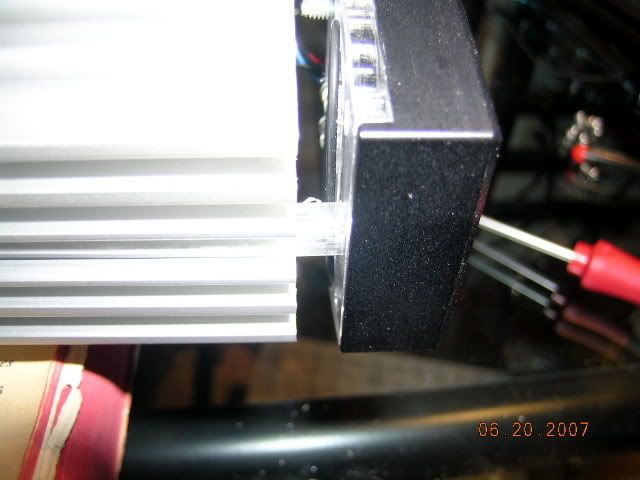
Okay we have had enough fun and games for a while. So back to the Aquaduct. Last night I started the disassembly and here I have already taken off the blue plexi top.
One thing that is very important about the un-tightening sequence is that you must use a cross pattern and only a twist or two of the driver per sequence. This will became apparent later on as to the why.
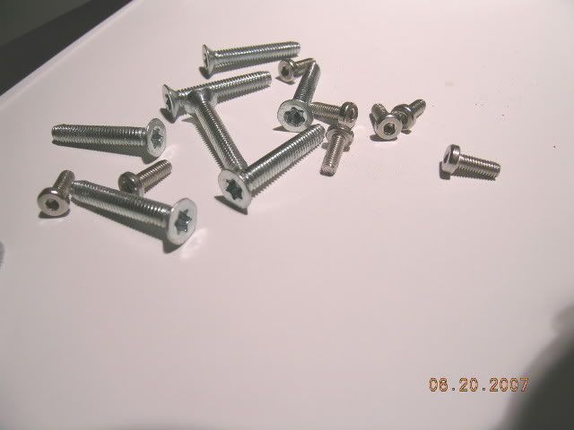
Make sure you bag up the screws as the flat head TORX screws may be hard to find in your locale.
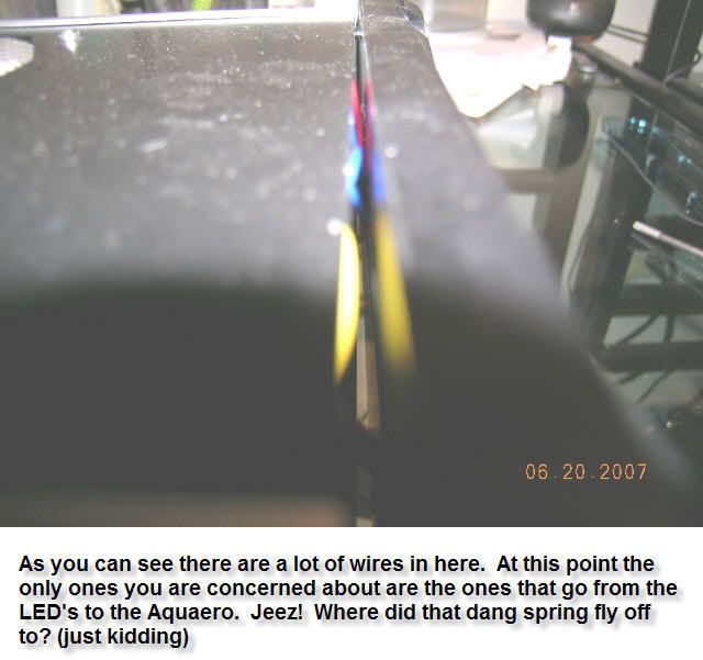
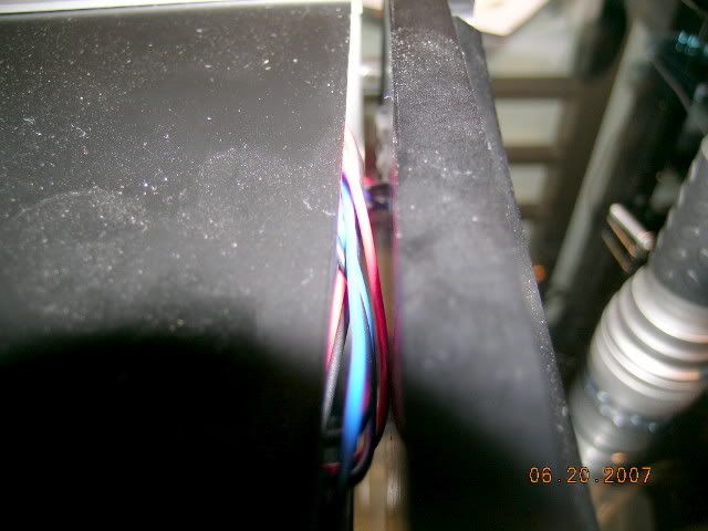
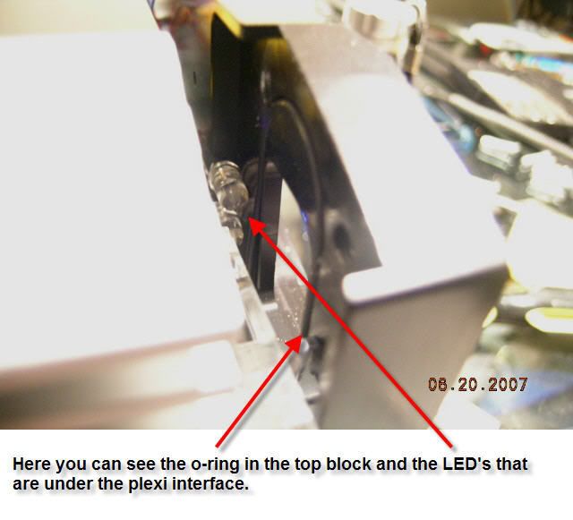
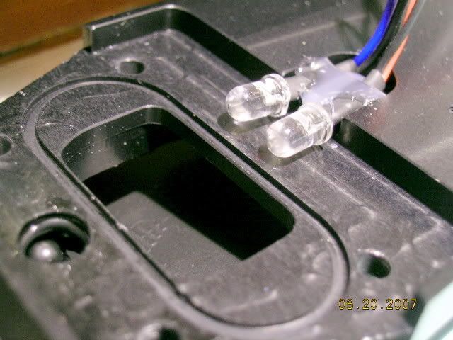
The wires you see here are the important ones to make sure you don't accidentally pull out of the top plate. These are the four (4) LED's that make up the blue glow you see in normal operation. These LED's can also be configured to glow red according to whatever temp you decide should be a visual warning.
When I first pulled out the top plate a ways I wasn't sure how all this was connected together so I decided to take off the plexi plate that you can see fitted into the top plate. This is totally unnecessary so don't do what I did. However, the plus side is that you get to see more pics, right?
That plexi plate was really difficult to get out. If you decide to take it out you will need some dental probes, some jewelers screwdrivers, and maybe some kind of really thin piece of flat stock about 1.5" wide.
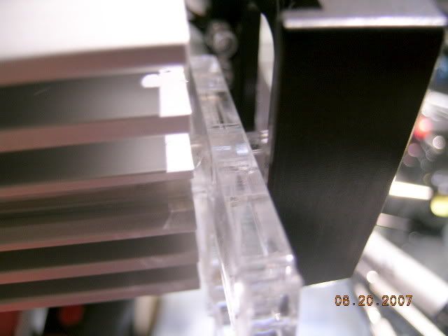
I finally got that dang plate out. Be careful you don't scratch it or you will be FUBAR as two o-rings seal against it.
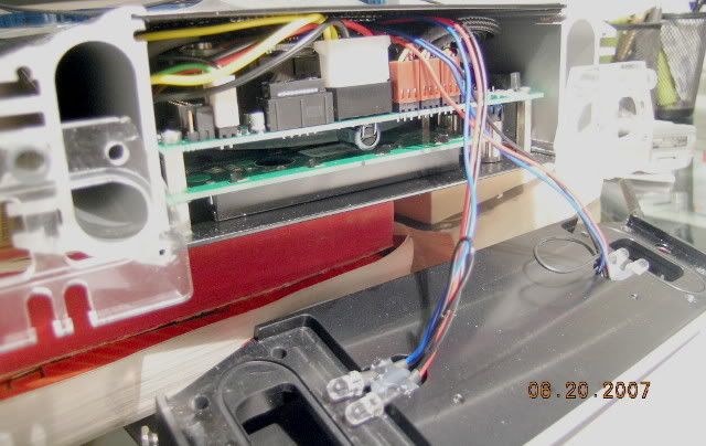
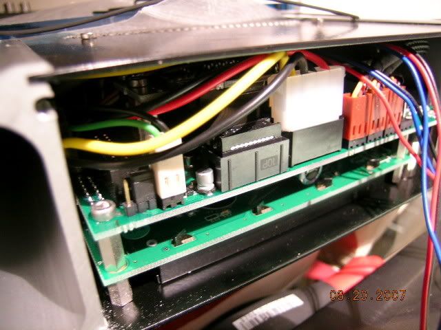
Now that I got the front plate off this is what is underneath it. For those in the know this looks like a pretty standard Aquaero circuit board, except for that big electrolytic capacitor just between the LCD board and the Aquaero board. Notice the sleeving on the fan wires? Now that's class to sleeve when no one will ever see it, huh?
Another odd thing is that you can see that they have the ribbon cable (to the left of the molex power connector) hooked up to something. Wonder what that is because AC has said that the Poweradjust unit can't be interfaced to the Aquaero and there certainly isn't an Aquastream in this Aquaduct. I guess we will see later what the surprise is.
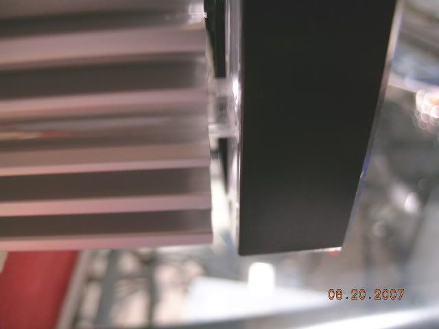
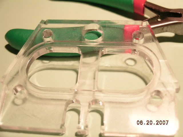
Here is one of the plexi plates. These also have an o-ring groove machined into it so that it seals against the aluminum side cooling extrusions.
I have been thinking about something here. See that gigantic flow chamber? I wonder how much extra flow you get from having that additional water cross section in the loop. That's 1.890" x 0.710" x about 23" x 2 sides plus the fairly wide water channel in the top plate.
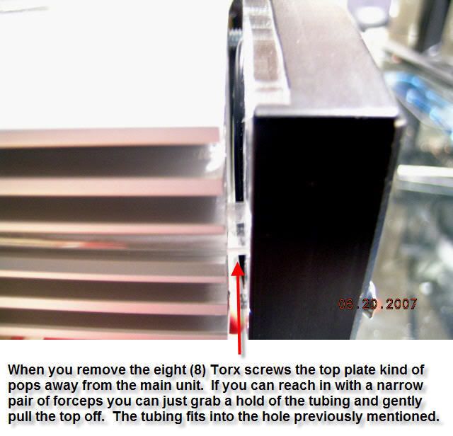
Remember when I suggested that you be very careful when unscrewing the Torx screws. Now you can see why I made the warning. The tapped holes are missing about 20% of their threads so creating a lateral force on the top while taking it off might FUBAR the threads. BTW, I would highly suggest that you cover that surface with some blue painters tape to protect that surface from scratches. O-rings don't like scratches.
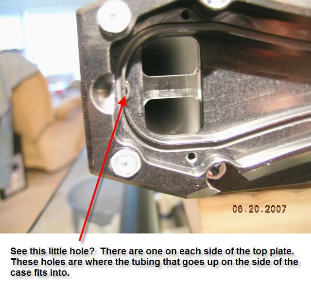
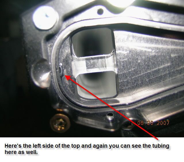
Here's another pic of the top plate. Make sure you don't pull the LED's loose as they fit exactly into the plexi plate shown above.
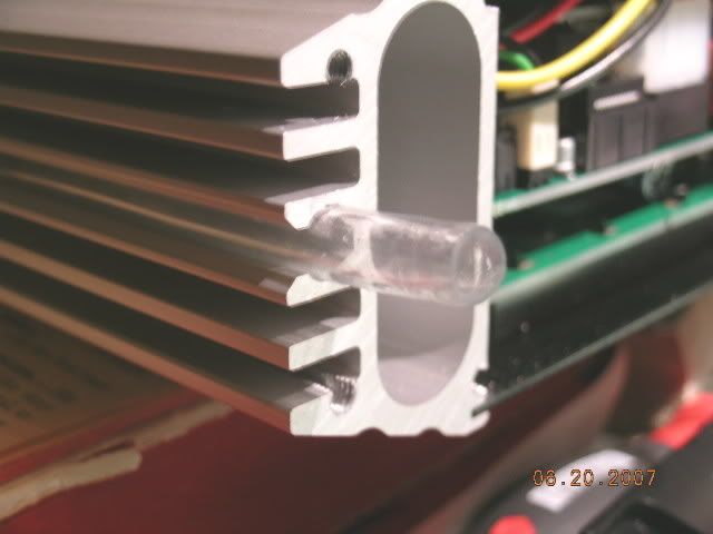
Hey, we got more cross sectional flow here add in another 6mm x 25" x 2 tubes.
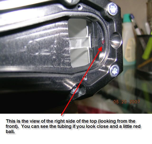
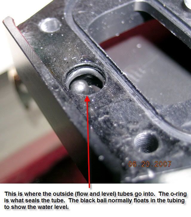
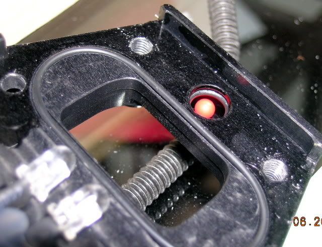
Here's the right side of the top plate. The little red ball only shows flow when you start up the Aquaduct. While it is in operation it sits up here in the top block.
The next job is to slide out the black plate you see at the top of the pic.
That's all for now till I take some more pics.
Last edited by Top Nurse; 06-21-2007 at 05:52 PM.

CEO Swiftech
What's even funnier is that they didn't want to touch that with a 10 foot pole.
Top Nurse,
Thanks for going through the trouble to disassemble this unit and take a lot of good pictures with text descriptions. Good work.
Very nice detailed work there Top Nurse!
750W Thermaltake Modular PSU
DFI UT X58-T3eH8
Core i7 920 @ 20 X 200 1.325V
CORSAIR XMS3 DHX 4GB (2 x 2GB) DDR3 1600
768 MB EVGA 8800GTX
1 X 36GB WD Raptor
2 X 150GB WD RAPTORS
1 X SpinPoint P Series SP2504C 250GB
1 X Maxtor 6L300S0 300GB
16 X NEC DVD Burner
7 120mm Yate Loon LED Intake Fan
4 120MM Yate Loon Exhaust Fan
28" HANNSPREE Monitor
Watercooling Loop:
1 X PA120.3
1 X PA120.2
2 X Laing DDC's w/EK-DDC Dual Turbo Top
7 X Yate Loon Blue LED Intake Fans
4 X Yate Loon Blue LED Exhaust Fans
1 X Swiftech GTZ
1 X GPU EK Fullcover Waterblock
1 X XSPC Dual Bay Reservoir 5.25" with Bubble Window

finally the "meat" or part of the unit...
Thanks for the nice nice.
Now that the [H] is back up I thought you might like to see my worklogs:
Heres my latest work on Feeding Frenzy Interlude, which is my work computer. It is really rather short in length, but I still got a bit left to do.
This worklog is called Feeding Frenzy, which is my screw around computer. This one might take some time to view as it has 736 posts and it hasn't been finished yet in two years now.
Now that is perserverence and I commend you on taking all those pictures and making that. Cant wait for more, excellent work!
For the record I am not sick, nor am I a gamer, nor am I a sick gamer. That name just sounds really cool to me but dont put me under that stereotype at all.
nevermind... addicted to COD4 and Free Online Games baby!

Thats looks absolutely awesome, and very nice job with the through pics !!!
FOLD for XS WCG ; or Rodzilla kills a kitten
@TN While I know we didn't agree on the Push Fit fittings (and now there seems to be evidence I may have been correct on this point) why have you not published temps?
I'm not looking for bashing or flaming. Just the facts.
I do appreciate your efforts. I just want to see the results.
See post #10
Sorry, but for now you will have to bug theseeker and R1ckCa1n to publish temps as they both have Aquaduct's running. After taking off the top plate I mentioned earlier this has a whole lot of wire and sleeving work to do. It will also take me a while to see if I can go up to 8mm ID tubing as that may not be possible within the mechanical construction constraints.
As for the push-fits I was correct within the parameters I set for using the tubing I use. PUR tubing is quite ideal for push-fits. When you try and muck up the tubing with stuff you currently use in big bores, that is when the problems start. So long as the proper tubing is used with the proper connector there are no problems.
Okay. Thats fair. I just didn't remember you setting the parameters when we discussed this last week. My bad.
Personally, as I said last week, I won't be using Push Fits until I hear a majority of people are successful.
I do find it interesting you don't back off with Push Fits after Gabe's results were posted.
Is this due to convenience or some other aspect I'm not aware of ???
Pretty nice pictures there TN! Can't wait to see temps.
Core i3-550 Clarkdale @ 4.2GHz, 1.36v (Corsair A50 HS/F) LinX Stable
MSI H55-GD65 Motherboard
G.Skill 4GBRL DDR3-1600 @ 1755, CL9, 1.55v
Sapphire Radeon 5750 1GB
Samsung F4 320GB - WD Green 1TB
Xigmatek Utgard Case - Corsair VX550


Please post the Results already.
Theres no point arguing over this.
I dont even think Temperatures are going to be that great, unless TP fabricates them, or has 320CFM Fans running over it.
CPU : E8400
Motherboard : Abit IP-35 Pro
Memory : GSkill DDR2-800 2GBHZ @ 1:1 445 4-4-4-12
Graphics Card : Palit HD4870 Dual Sonic
Display : Dell E228WFP
Storage & OS : 1TB | Windows 7 64bit
Sound Card & Speakers/Headphones : X-Fi Platinum (HotRod) > Zero DAC > BeyerDynamic DT990 Pro
Peripherals : Razer ProType Keyboard | Steelseries Ikari Optical | Razer Goliathus Speed.
Case : Coolermaster ATCS 840
PSU : OCZ GamerXtreme 700W
Hmm. Okay. I'll sit and listen.
It's because they work perfectly for me and thousands of users worldwide. It's only here in the USA that people haven't been exposed to them to any great degree in the water cooling scene. Convenience is another factor. I put a flow meter in my loop and it was installed and running within about 10 minutes. I can change my loop order in less than 20-30 minutes. And best of all they don't leak like hose barbs.
Maybe you lie, but I don't.
I assume you didn't read the thread from your comments...
^^ Lol, That was a joke.
Ill quote Petra's Sig? :P....
Lol, Why didnt you post temp's as soon as you got it, and before your DDC Mods?She canna take it anymore captain, we're experiencing a catastrophic sense-of-humour failure! ;p
I hope your atleast jotted them down, to refer to them, as before mods/after mods.
CPU : E8400
Motherboard : Abit IP-35 Pro
Memory : GSkill DDR2-800 2GBHZ @ 1:1 445 4-4-4-12
Graphics Card : Palit HD4870 Dual Sonic
Display : Dell E228WFP
Storage & OS : 1TB | Windows 7 64bit
Sound Card & Speakers/Headphones : X-Fi Platinum (HotRod) > Zero DAC > BeyerDynamic DT990 Pro
Peripherals : Razer ProType Keyboard | Steelseries Ikari Optical | Razer Goliathus Speed.
Case : Coolermaster ATCS 840
PSU : OCZ GamerXtreme 700W
She has not used it yet. How can you post temps if it has not been used.
agree 100%
750W Thermaltake Modular PSU
DFI UT X58-T3eH8
Core i7 920 @ 20 X 200 1.325V
CORSAIR XMS3 DHX 4GB (2 x 2GB) DDR3 1600
768 MB EVGA 8800GTX
1 X 36GB WD Raptor
2 X 150GB WD RAPTORS
1 X SpinPoint P Series SP2504C 250GB
1 X Maxtor 6L300S0 300GB
16 X NEC DVD Burner
7 120mm Yate Loon LED Intake Fan
4 120MM Yate Loon Exhaust Fan
28" HANNSPREE Monitor
Watercooling Loop:
1 X PA120.3
1 X PA120.2
2 X Laing DDC's w/EK-DDC Dual Turbo Top
7 X Yate Loon Blue LED Intake Fans
4 X Yate Loon Blue LED Exhaust Fans
1 X Swiftech GTZ
1 X GPU EK Fullcover Waterblock
1 X XSPC Dual Bay Reservoir 5.25" with Bubble Window
I agree TN over at [H] was unbarerable. But he(she) does make solid points . and yes a well designed low flow system is just as efficient as a high flow system.
As for mixing aluminium and copper . It can cause problems. So I decided to to experiment. Almost 2 years ago I bought a koolance cooling system and decided to use it with a storm and maze 4 using koolance liquid. I checked the parts every 6 months. after a year and 1 1/2 years without changing the coolamt zero corrosion. NONE nada, I will post full results at the end of 2 years with testamonials from the people involved in this experiment.
I don't know Marci or Cather. But have read a lot about what they have posted and it is in fact good stuff. Cathers storms is nothing but
I used marci rads in everthing their great . I now use only his 160's in some case's as we now have our own 120.3 type rad and its very efficient.
But 4 160's in a system is very hard to beat their that good. I wish marci would change his 160's inlet and outlet so as to use G 1/2 Its hard to clean them out after I modd them. But I really like the 160's.
Hopefully we can duplicate their performance soon enough haven't succeeded yet but soon. So I don't have to modd anymore 160's it is a pain. in the arse.
Marci if you read this. The reason I modd your 160's is because the flow threw a 160 's is infact the bottle nick for the systems i use them in .
I use 2 pumps going into a 6 loop flow control set up . so I need to run between 6-8 gpm threw the 4 160's . I have found that 3/4 I.D. copper tubing works great to connect the 4 rads. All the loops use 3/8 copper tubing I.D. Except the hard drive loop 1/4 works fine their and the chipset and memory loops. the 2 video card loops and 2 cpu loops are 3/8 .
Of course for now 1 of the cpu is blocked off till skulltrail but I have tested flow with all blocks in place and without modding the 160's they bottleneck the flow. 2 gpm to the 3/8 loops and 1 gpm to the 1/4 loops.
Didn't bother as I had no computer to add it into at the moment. I know most people would want to immediately slap it into some rig and take it for a spin. However, in case you hadn't noticed I take the road less travelled and decided to just start modding. For me modding is the fun part and what I get out of it is just secondary gain. I know that any mods I make will be beneficial so who cares what it did before I mod it?
Last edited by Top Nurse; 06-22-2007 at 09:42 AM.
Okay, time to do some more surgery. The next operation is to get the back panel off. To do this you have to take off all the 3mm fan screws. Anotherhere as two of the screws had the socket hex stripped. Not fun to have to get a pair of vice-grips out to get them off. Well no big deal as I plan on only using stainless button heads on re-assembly.
Here you can see me sliding off the back panel.
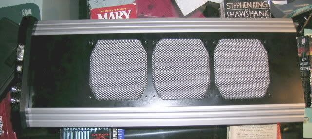
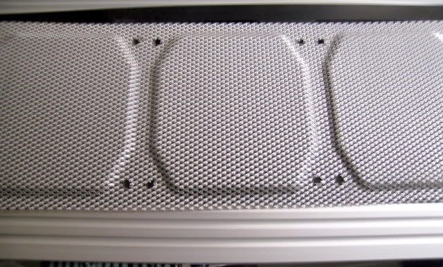
In case you were wondering how they did that fancy grill this is it. AC has started selling this grill in some pre-made cases so I think it is only a matter of time before they sell them by themselves.
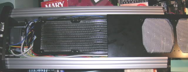
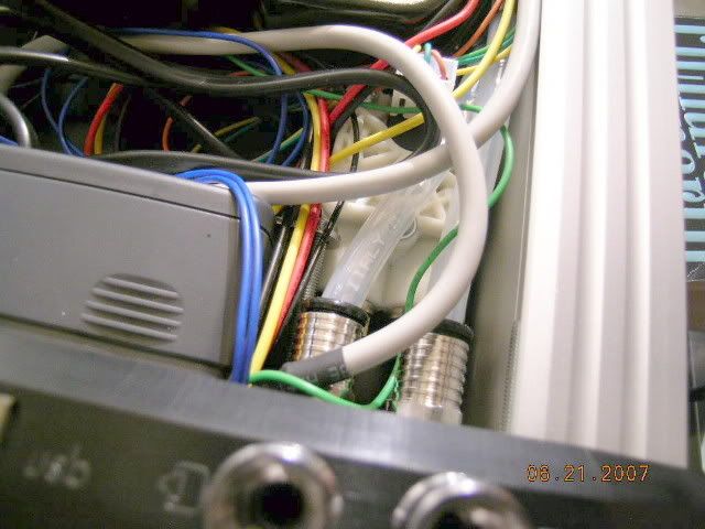
Here's looking at the bottom inside of the Aquaduct.
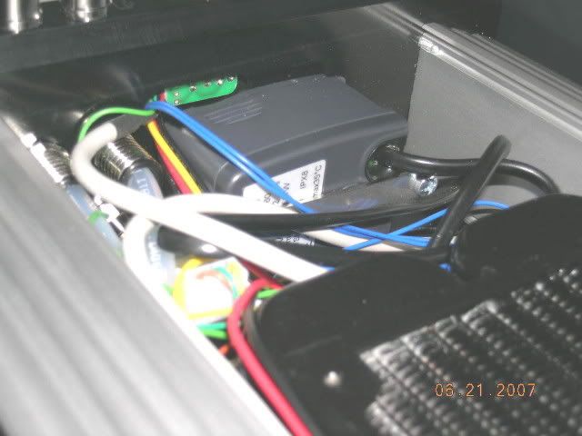
Here you can see the Eheim Compact 600 pump and the DigMesa flow meter is barely visible under the tubing on the right side. I take back what I said earlier about their good wiring skills. All these wires are going to have to be customized to the proper length and sleeved. How about a plexi back plate here?
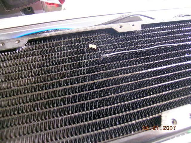
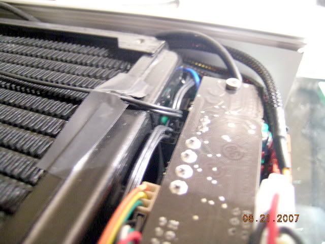
Here is a close-up of the 360 radiator and the temp probe they have placed to measure the air temp after leaving the radiator.
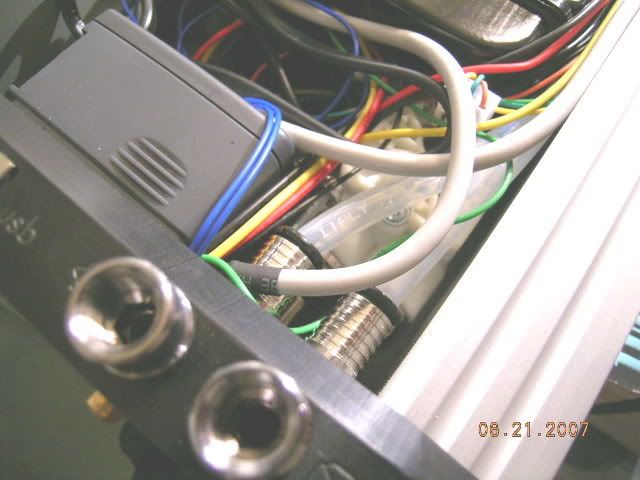
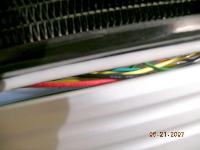
The water tubes go along both sides of the radiator. Seems strange, but I guess we will have to wait till further disassembly to see what's up. The wires also are routed through this area on both sides as well (more sleeving and shortening). Using bigger tubing looks kind of tight in here. Guess I got to order the tubing and see what we see.
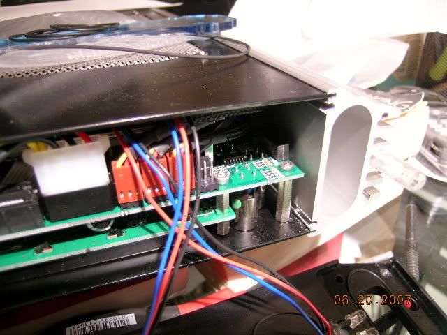
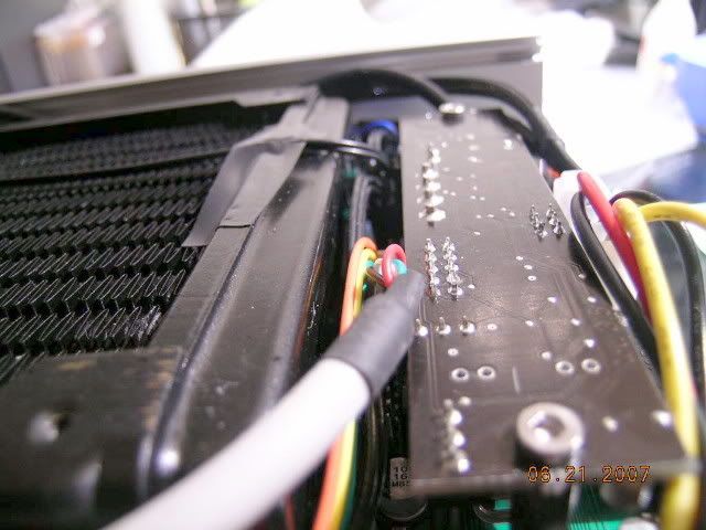
The circuit board you see here is the pump controller board and is piggy backed to the Aquaero. In addition it has a ribbon cable to allow control and create a feed back loop to the software/hardware.
More later when I have time to process more pics.
 Posting Permissions


Bookmarks