

Yes, although I am pretty sure that with 1.7 Volt we will have to adjust the Current limiter.Originally Posted by VoRtAn_MaDgE
This is the 3.5Kohm resistor from pin 10 to pin 11.


Yes, although I am pretty sure that with 1.7 Volt we will have to adjust the Current limiter.
This is the 3.5Kohm resistor from pin 10 to pin 11.
Last edited by t024484; 03-23-2006 at 08:39 AM.
No it is not hardwired.
The traces are going to ground or via a resistor to +5Volt I suppose, in order to get a 0 or a 1.
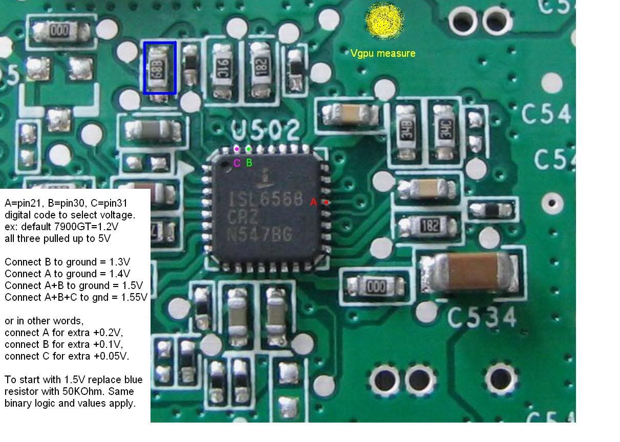
i made a pretty picture
i did none of this. all credit to the developers
Last edited by s e t h; 03-23-2006 at 09:32 AM.
There are two possibilities:
1) Either you do not change any resistor at all, and then this table applies:
options starting at 1.200 Volt with the existing sertting of "01110"
-------1.200-1.250-1.300-1.350-1.400-1.450-1.500-1.550
Pin22----0-----0----0------0------0-----0------0----0
pin21----1-----1----1------1------0-----0------0----0
pin30----1-----1----0------0------1-----1------0----0
pin31----1-----0----1------0------1-----0------1----0
pin32----0-----0----0------0------0-----0------0----0
2)Or you change the resistor as in the picture from Flytek to 50Kohm,
then this table applies starting from 1.5 Volt for the existing setting of "01110"
-------1.500-1.525-1.550-1.575-1.600-1.625-1.650-1.675-1.700Volt
Pin22----0-----0----0------0------0-----0------0----0-----0
pin21----1-----1----1------1------1-----1------1----0-----0
pin30----1-----1----1------0------0-----0------0----1-----1
pin31----1-----0----0------1------1-----0------0----1-----1
pin32----0-----1----0------1------0-----1------0----1-----0
In the Picture that FLYtek mailed, the wrong combination of resistor and table was made.
Simplified, I removed pin info, diagrams tables etc.
24/7: A64 3000+ (\_/) @2.4Ghz, 1.4V
1 GB OCZ Gold (='.'=) 240 2-2-2-5
Giga-byte NF3 (")_(") K8NSC-939
XFX 6800 16/6 NV5 @420/936, 1.33V
t024484
Let's make a guide, so everyone can do this. If you add that table in the picture and mark the mod points. It will be easier to understand, if someone haven't read this thread before.
You are as good as your samples are!
***Deimos*** did it already! Thank's
You are as good as your samples are!
ingenius!
after doing the 50k mod, (must do before this) this should be the 1.6 and 1.7v mod. but let me test it out 1st. prolly need the ocp mod 1st too


Just so DAMM small to solder.
and the ISL is very exposed to the heat+it being so complicated makes i more likly to kill the chip when soldering maybee?
That's the whole story.***Deimos
Simplified, I removed pin info, diagrams tables etc.
Well done Deimos
The info from LardArse should also be used because this makes it a lot easier to solder.
Last edited by t024484; 03-23-2006 at 10:44 AM.
It is extremely small, seems the easiest way is to just mod the resistor and stick with 1.5v
- i7 5820K | Asus X99 Deluxe | 16GB Corsair Vengeance LPX | eVGA GTX 970 SC SLI | Asus PB278Q | 250GB Samsung 840 | 11TB HDD Storage | Steel Series Rival & QcK+ | Razer Orbweaver & Black Widow Ultimate '14 | Corsair RM1000W | Win 8.1 -
- Ek Supremacy Nickel | Alphacool NexXxos UT60 360MM | Coolgate UHE 360MM | Bitspower Water Tank Z-Multi 150 | EK D5 CSQ Top | Alphacool VPP D5 | Corsair SP120 HP's | Corsair 900D | Xbox One & PS4 | Sharp Aquos Q 60" | Astro A50 -
~ Gone but never forgotten: Xtreme Legend - Hallowed Point - Enthusiast - Bencher - Friend ~
The easiest way would be to stick one end of wire right between ground and pins #30 and #31, and get +0.25V.
With such small places to solder, its difficult to get one exact pin. But this way, its easier.. 1.2-1.45V made easy.
Last edited by ***Deimos***; 03-26-2006 at 11:01 PM.
24/7: A64 3000+ (\_/) @2.4Ghz, 1.4V
1 GB OCZ Gold (='.'=) 240 2-2-2-5
Giga-byte NF3 (")_(") K8NSC-939
XFX 6800 16/6 NV5 @420/936, 1.33V
Can we do the pencil trick between pin 21 and 22?
This should set 1.4V VGPU right away.
Last edited by TimeOut; 03-23-2006 at 11:08 AM.
Congratulation men, you did it.
Did anyone check where via lead on the other side of the PCB, because soldering directly on ISL legs sounds quite hard.
Is 1.5V and higher not too high for the regulator embedded on the GT ? (that are different from GTX )
DFI NF4 Ultra-D
Opteron 165 @ 3.0GHz Max | Opteron 146 @ 3.2GHz Max
Leadtek PX6200TD GF6200 @ 692/743 Max
Sapphire X800-XL R430 @ 549/579 Max
Sapphire GTO² R480 @ 684/633 Max
2x512 Twinmos UTT 270 2-2-2-5 @ 3.63V
2x512 CMSAM New BH5 250 2-2-2-5 @ 3.5V
Waterchiller by Learn R22-225W
#5 6200-3DM01:21891 |WR 6200-3DM03:8753 | WR 6200-3DM05:3946 | WR 9800Pro-3DM05(110):3676 | #2 X800XL-3DM05:6660
| WR X800 GTO² 3DM05:8050 | WR X800 GTO² 3DM03:16472
Overclocking-Masters.com
So this is correct right (just asking to be sure)? to get 1.5V

Dell: Dude whats that smell, its my Dell burning like hell.
Oh I like that!
- i7 5820K | Asus X99 Deluxe | 16GB Corsair Vengeance LPX | eVGA GTX 970 SC SLI | Asus PB278Q | 250GB Samsung 840 | 11TB HDD Storage | Steel Series Rival & QcK+ | Razer Orbweaver & Black Widow Ultimate '14 | Corsair RM1000W | Win 8.1 -
- Ek Supremacy Nickel | Alphacool NexXxos UT60 360MM | Coolgate UHE 360MM | Bitspower Water Tank Z-Multi 150 | EK D5 CSQ Top | Alphacool VPP D5 | Corsair SP120 HP's | Corsair 900D | Xbox One & PS4 | Sharp Aquos Q 60" | Astro A50 -
~ Gone but never forgotten: Xtreme Legend - Hallowed Point - Enthusiast - Bencher - Friend ~
You do the same with pins #21 and #22 and get +0.20V or 1.40V VGPU
So that's for vgpu, then just replace the resistor with a 50k and ground it to pin 21? I may get a GT now...
Phenom II 940 BE / ASUS M4A79 / HD5770 Crossfire
3770mhz CPU 2600mhz NB | DDR1040 5-5-5-15 | 900/1250
Err seriously? That simple?
- i7 5820K | Asus X99 Deluxe | 16GB Corsair Vengeance LPX | eVGA GTX 970 SC SLI | Asus PB278Q | 250GB Samsung 840 | 11TB HDD Storage | Steel Series Rival & QcK+ | Razer Orbweaver & Black Widow Ultimate '14 | Corsair RM1000W | Win 8.1 -
- Ek Supremacy Nickel | Alphacool NexXxos UT60 360MM | Coolgate UHE 360MM | Bitspower Water Tank Z-Multi 150 | EK D5 CSQ Top | Alphacool VPP D5 | Corsair SP120 HP's | Corsair 900D | Xbox One & PS4 | Sharp Aquos Q 60" | Astro A50 -
~ Gone but never forgotten: Xtreme Legend - Hallowed Point - Enthusiast - Bencher - Friend ~
I want to know as well, as my 7900gt is on its way and I already have a NV Silencer 5 for it. However, I can't solder for the life of me and I want a simple volt mod that does not require any skill.
I'm afraid it won't be much easier...
BUT: If Pin 32 and pin 22 is *already* '0', why not just connect
Only pin 32 to pin 30 and 31 to get 1,350V or
Only pin 22 to pin 21 to get 1,4V or
pin 32 to pin 30 and 31 AND pin 22 to pin 21 to get 1,55V
Would that work?

Last edited by Belarnion; 03-23-2006 at 01:30 PM.
If you guys encounter problems soldering those tiny legs of the intersil chip just isolate the closests legs near the one to solder with seal string for example...
"God...i know she's dead :'( but keep her soul alive because in my heart she will never die :'(" VoRtAn_MaDgE
Nc te eskecerei avó! :'(
Anyone thought of using a DIP switch?
Also you can search for the same point in other PCB location, checking continuity between it and the pin you search for. Do you understand what i mean ? ( im not sure of the words to use)
Asus P5K Premium//Intel E6600@3,6ghz//Corsair PC6400C3@500 4-4-4-12 2,2v//8800GTS G92//Audigy 2 ZS//SeaSonic M12 700W & LianLi V2000B
I think this would work.
But, getting pencil in there is just as difficult as soldering.
24/7: A64 3000+ (\_/) @2.4Ghz, 1.4V
1 GB OCZ Gold (='.'=) 240 2-2-2-5
Giga-byte NF3 (")_(") K8NSC-939
XFX 6800 16/6 NV5 @420/936, 1.33V
 Posting Permissions


 Reply With Quote


Bookmarks