

Hmm... I hadn't thought of that.Originally Posted by jumper2high


Hmm... I hadn't thought of that.
I'm doing science and I'm still alive...
yes, I also found that using hot air gun has much better success rate than drag soldering for this kind 0.33mm leg spacing IC. but it should be done very carefully, 360 degree maximum 10 second. After the solder melt and the IC self align , hold the temperture for 10s and stop the heat gun immediately. For me, drag soldering is good for >0.4mm leg spacing.

Another item on sale from diyinhk
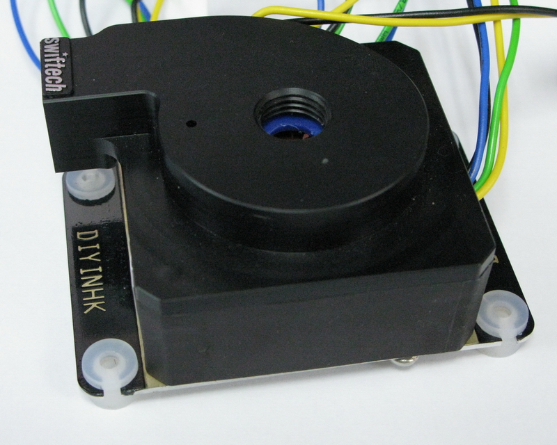
Laing DDC water pump 12W swiftech MCP350 with heatsinkEach pump is modded and tested one by one. The PCB has going over three version and It's 100% bug free. We only use top quality component, Dale resister, Japanese capacitor, 2oz copper PCB, Gold plated heatsink, Kester lead free solder etc.. As the price told, profit is not the target, more user of our product and your good comment is the mostly wanted.
Last edited by SpuTnicK; 01-25-2011 at 10:39 AM.
An unfortunate person is one tries to fart but sh1ts instead...
My Water Cooling Case Build (closed)
I would have to question the actual effectiveness of that heat sink with it being buried inside the plastic housing.
Circles SucQ!
If your annoyed by sigs telling you to put things in your sig, then put this in your sig
Bribery won't work on me...just say NO to AT!!!
+1 on doubts.
I remember simple mod with cutting holes in pump plastic casing, was very effective in bringing temps down even with original PCB.
This is another PCB mod, sanyo motor driver
Test shows that without the heatsink, the pump can only run with stock top. i.e. maximum ~0.9A.
with the heatsink, it can run with aftermarket top and up to 1.5A before trigger the overheat protection. The pump stop when overheat detect, and auto restart when temperature is reduced. This should be a standard feature seems not available in the Laing original PCB.
this sanyo uses "sine wave" can drive motor more silent than "PWM", but more heat. Test shows that Toshiba PWM can drive up to 2A without extra heatsink. for xtremer, toshiba PWM. for silent love - sanyo sine wave
Last edited by wizard1238; 01-25-2011 at 04:32 PM.
@wizard1238
How do you mount the pump as there is no mounting ears?
System:1
Banchetto
I7 860 4.2Ghz | Asus Maximus III Formula | EVGA 2 GTX295's | 4Gb (2x2Gb) Dominator GT Ram @ 2000 8-9-8-24-1T | OCZ RevoDrive3 120Gb SSD | Barracuda 500Gb HDD
W/C System
Apogee XT | EK-FC285 Nickel| Thermochill PA 120.3 | TFC Xtender Shrouds |DD Monsoon Premium D5 Dual Bay Reservoir | MCP655-B|Noctua NF-P12| HydrX | B*P Compression Fittings
System:2
Sunbeamtech Ultra-Tech Station
I7 875K 4.4Ghz | EVGA P55 LE | PNY Quadro FX4800 | 4Gb (2x2Gb) Dominator Ram @ 1600 8-8-8-24-2T | 2 OCZ Vertex2 60Gb SSD RAID 0 | Barracuda 500Gb HDD
W/C System
Apogee XT | DD Koosah | 2 Thermochill PA 120.1 | TFC Xtender Shrouds | EK-DDC X-RES 100 | MCP350 | Noctua NF-P12 | Indigo Xtreme | HydrX | B*P Compression Fittings
System Videos
I'm not saying it doesn't work, I'm saying it doesn't work as well as it could.
Heat sinks require a constant supply of moving air in order to be able to efficiently shed the heat they collect, yours isn't getting any fresh air because it's inside the pump housing. If the housing had even a few holes in them, the heat sink would do a much better job.
Circles SucQ!
If your annoyed by sigs telling you to put things in your sig, then put this in your sig
Bribery won't work on me...just say NO to AT!!!
Yes, It should perform better if open to free air
But it has already let the sanyo driver run at it's full potential 1.5A inside the original plastic housing.
Without it, we can only use stock top and test shows that the sanyo driver will overheat at only 0.9A even run nude without the original plastic housing
Last edited by wizard1238; 01-25-2011 at 10:57 PM.
Maybe this thread might be of interest. Should be simple to make with dremel at hand. This was done by just drilling holes in hausing.
But though not the cheapest, most effective and best looking probably would be this replacement pump hausing by Koolance. It's not only air open, but also from metal, +heatsink, +thermal pads from fets to heatsink, +superb looks.
I'm still confused as to why Koolance decided to go with the color they choose for it. I really think either nickle or black would've looked much better.
Little expense had been spared to create the impression that no expense had been spared. - Hitchhiker's GuideMondays:It's better to ask dumb questions now, than to look stupid later
the koolance solution is good for long run and it's the only solution for the original laing PCB. It's amazing and superb looksheat transfer from IC leg to PCB first to thermal pads to heatsink.
this gold plated heatsink is designed only for this sanyo solution, It make direct contact to the IC top for immediately and quick heat dissipation. I tried 3M silicone thermal pad between the heatsink and sanyo IC top in the very beginning, the pump can run up from 0.9A to 1A only and trigger the overheat protection...direct contact heatsink rise the overheat protection trigger originally at 0.9A to 1.5A. Actually, I am very lucky to find it out, the 12W pump can use aftermarket top and run stable finally before it's go publicActually, 40% headroom may be too much even for aerospace industry
Last edited by wizard1238; 01-26-2011 at 02:31 AM.
All it is 4 metal springs. Although I haven't used the pumps yet but I do not think they are all that useful.
Anyways is anyone willing to do the soldering required to these PCBs if I were to send the gear to him?

I had a DDC pulled from a mac with one of those compensator things. The rubber diaphragm split and it leakedI'd sooner get a DDC without that compensator thingy.
The Cardboard Master Crunch with us, the XS WCG team
Intel Core i7 2600k @ 4.5GHz, 16GB DDR3-1600, Radeon 7950 @ 1000/1250, Win 10 Pro x64
This is a common issue with the DDC-VC pumps once they are taken out of the 12psi pressure loop and used in a regular WCing loop with a RES. The diaphragm has no pressure to keep it pressed against the backing plate held by the four springs, thus the rubber diaphragm can easily split.
Support Your Local Sheriff - At high noon
My Heatware http://www.heatware.com/eval.php?id=63611
The pump Maverick, BMaverick
Honestly the diaphragm doesn't look all that cheap to me. Both of mine look to be in great shape. And if by chance it leaks from there I don't see why I couldn't just block small hole to the diaphragm w/ a dab of silicon.
I would like to order one to play with, but how do you mount it?
System:1
Banchetto
I7 860 4.2Ghz | Asus Maximus III Formula | EVGA 2 GTX295's | 4Gb (2x2Gb) Dominator GT Ram @ 2000 8-9-8-24-1T | OCZ RevoDrive3 120Gb SSD | Barracuda 500Gb HDD
W/C System
Apogee XT | EK-FC285 Nickel| Thermochill PA 120.3 | TFC Xtender Shrouds |DD Monsoon Premium D5 Dual Bay Reservoir | MCP655-B|Noctua NF-P12| HydrX | B*P Compression Fittings
System:2
Sunbeamtech Ultra-Tech Station
I7 875K 4.4Ghz | EVGA P55 LE | PNY Quadro FX4800 | 4Gb (2x2Gb) Dominator Ram @ 1600 8-8-8-24-2T | 2 OCZ Vertex2 60Gb SSD RAID 0 | Barracuda 500Gb HDD
W/C System
Apogee XT | DD Koosah | 2 Thermochill PA 120.1 | TFC Xtender Shrouds | EK-DDC X-RES 100 | MCP350 | Noctua NF-P12 | Indigo Xtreme | HydrX | B*P Compression Fittings
System Videos
I know it was already posted somewhere on XS, but just keep all in one place:
This is a Laing DDC pump bottom heatsink with vibration damper. It is suitable to all version of DDC pump include MCP350 MCP355, the newest MCP35X, and the taller Apple G5 VC version.
LinkIt is a gold plated metal plate with direct contact to the ddc bottom. The metal plate has a silicone feet to ensure better air flow in the bottom. It avoid the danger of overheat problem like the traditional way which fullly cover the bottom with sponge gel for vibration damping. The silicone feet also turely decoupled the ddc pump, not direct load path from the pump to the computer case, it is ture isolation.
do i hear gold?
BTW, I am Xtreme Enthusiast now
Last edited by SpuTnicK; 02-06-2011 at 12:43 PM.
An unfortunate person is one tries to fart but sh1ts instead...
My Water Cooling Case Build (closed)
This bottom is made from mcpcb (metal core pcb). It has 2OZ copper layer and 1.6MM aluminum layer(like a double layer heatsink).
This type of professional PCB is used for best thermal transfer of electronic component. It is much expensive than ordinary PCB.
The copper area under the DDC bottom is gold plated, it uses the same treatment of PCB terminal(aka gold finger).
Last edited by wizard1238; 02-06-2011 at 07:08 PM.
DDC pump repair in 3 minutes guide video
http://www.youtube.com/watch?v=3_Rpty4lWgg
Is there another part to that?
But you didn't finish soldering the wires to the PCB...
Pretty neat seeing the heat gun soldering iron in action.
Mine is sat in customs still
we need part two.
great work.
An unfortunate person is one tries to fart but sh1ts instead...
My Water Cooling Case Build (closed)
I just been chatting to the man on eBay
Seams like they are apealing to our need. Most of us can solder. Im sure we don't need the reflow air gun to remove the coil wires, an soldering iron will do fineThank you for interesting in our product, The Sanyo pcb assembled version for the 10W black rotor DDC is on sale in the ebay store now. The Toshiba assembled pcb for the 18W purple rotor DDC will be on sale soon. What is your ddc rotor color to repair? Thanks
 Posting Permissions


 Reply With Quote


Bookmarks