MMM
Page 1 of 2 12 LastLast
Results 1 to 25 of 36

Thread: TEC Chiller Project

  1. #1
    Xtreme Member
    Join Date
    Jun 2004
    Location
    Brighton, UK
    Posts
    131

    TEC Chiller Project

    Hi everyone
    I currently have a pretty high-end watercooling setup:
    Feser 480 Rad with 4 San Ace Fans (1600rpm)
    Laing 3.1 with XSPC Res Top
    Fuzion V1 Block cooling a Q9650 at 4.13 Ghz/1.31 volts (currently)
    2xATI 4870s in Crossfire at 815/925 with EK full cover waterblocks
    Gigabyte EP45 Extreme motherboard, also watercooled.

    But being a bit of a technophile who likes building stuff, I’ve decided to build a TEC-based chiller
    So here’s the plan:
    2 QMax 437 (allegedly, apparently more like 400- thanks for all your advice Uncle Jimbo ) TECs from FrozenCPU running in parallel, undervolted to 12 volts (so CoP > 1)
    3-15 Volt 25 Amp continuous switched mode power supply (£59 reduced from £99- bargain)
    TEC power controlled via the PWM booster described by Ultrasonic 2 (thanks for your help on this too) hooked up to a T-Balancer BigNG (with the capacitor on that output channel removed)
    Custom TEC waterblocks
    Cold side loop pumped using my existing Laing 3.1 with XSPC Res Top (insulated)
    Chiller cooling CPU only, graphics cards and motherboard waterblocks will be in the separate hotside loop pumped by another Laing 3.1 with XSPC single Bayres and cooled by the Feser 480
    T-Balancer will control the hotside loop temperature via the rad fans
    First off the waterblocks- since I work in a University I fortunately have access to excellent machine shop facilities which the guys are happy to let me use. Block bases are copper 80mm x 140mm x 12mm thick, with 5mm wide x 10mm deep channels, flycut on the bottom and then lapped:

    I did these by hand (took a while...) since I have no idea how to program the CNC mills
    The tops are 8mm Delrin, sealed onto the blocks with 0.5mm thick butyl rubber gaskets which cover the whole surface and so seal the tops of the water channels from one another.
    The TECs are clamped between the 2 blocks using Arctic Ceramique TIM and 6 M4 bolts tightened to 15 in lbs each which gives a clamping pressure of 250 psi- mind you I couldn’t get hold of a suitable torque wrench so used the trusty long Allen key and spring gauge method. Here is the finished article- not insulated as yet:


    More to follow soon.....
    EVGA Classified, i920 @ 4200 24/7, 3 x 2GB XMS CAS7, ATI 5870 FC EK W/C , Bequiet 850W PSU, XFi Music, Vista 64 Bit, peltier-chilled water-cooling

  2. #2
    Xtreme Enthusiast
    Join Date
    Jun 2008
    Location
    Somewhere South, Great Britain.
    Posts
    661
    Quote Originally Posted by uranium View Post
    But being a bit of a technophile who likes building stuff, I’ve decided to build a TEC-based chiller
    So here’s the plan:
    2 QMax 437 (allegedly, apparently more like 400- thanks for all your advice Uncle Jimbo ) TECs from FrozenCPU running in parallel, undervolted to 12 volts (so CoP > 1)
    3-15 Volt 25 Amp continuous switched mode power supply (£59 reduced from £99- bargain)
    TEC power controlled via the PWM booster described by Ultrasonic 2 (thanks for your help on this too) hooked up to a T-Balancer BigNG (with the capacitor on that output channel removed)
    Custom TEC waterblocks
    Cold side loop pumped using my existing Laing 3.1 with XSPC Res Top (insulated)
    Chiller cooling CPU only, graphics cards and motherboard waterblocks will be in the separate hotside loop pumped by another Laing 3.1 with XSPC single Bayres and cooled by the Feser 480
    T-Balancer will control the hotside loop temperature via the rad fans
    First off the waterblocks- since I work in a University I fortunately have access to excellent machine shop facilities which the guys are happy to let me use. Block bases are copper 80mm x 140mm x 12mm thick, with 5mm wide x 10mm deep channels, flycut on the bottom and then lapped:

    I did these by hand (took a while...) since I have no idea how to program the CNC mills
    The tops are 8mm Delrin, sealed onto the blocks with 0.5mm thick butyl rubber gaskets which cover the whole surface and so seal the tops of the water channels from one another.
    The TECs are clamped between the 2 blocks using Arctic Ceramique TIM and 6 M4 bolts tightened to 15 in lbs each which gives a clamping pressure of 250 psi- mind you I couldn’t get hold of a suitable torque wrench so used the trusty long Allen key and spring gauge method. Here is the finished article- not insulated as yet:
    Looks good...you've done your research.
    It's a moot point, so long as you don't crack your pelts but 15lbs per screw is well over 250psi.

    T = (C x D x F x in²) / (# of screws)

    T lbs per screw
    C is torque coef. 0.2 = stainless steel
    D nom. size M4 = 0.112
    F force we will use 300psi
    in² 2x 62mm x 62mm = 11.52

    (0.2 x 0.112 x 300 x 11.52) / 6 = 12.9 lbs per screw for 300psi

    Torque wrenches are often way over ...more often than not starting at 20inch lbs you needed a torque screwdriver - much smaller torques.

    Pleased to see you got yourself a nice variable PSU those meanwell things are not as useful as they could be.
    Last edited by zipdogso; 07-28-2009 at 03:59 PM.

  3. #3
    Xtreme Member
    Join Date
    Jun 2004
    Location
    Brighton, UK
    Posts
    131
    Thanks

    With respect, M4 is 4mm major diameter which is 4/25.4 in inches= 0.157, which would make my calculation correct European versus US Screw sizes!!

    Geoff


    Quote Originally Posted by zipdogso View Post
    Looks good...you've done your research.
    It's a moot point, so long as you don't crack your pelts but 15lbs per screw is well over 250psi.

    T = (C x D x F x in²) / (# of screws)

    T lbs per screw
    C is torque coef. 0.2 = stainless steel
    D nom. size M4 = 0.112
    F force we will use 300psi
    in² 2x 62mm x 62mm = 11.52

    (0.2 x 0.112 x 300 x 11.52) / 6 = 12.9 lbs per screw for 300psi

    Torque wrenches are often way over ...more often than not starting at 20inch lbs you needed a torque screwdriver - much smaller torques.

    Pleased to see you got yourself a nice variable PSU those meanwell things are not as useful as they could be.
    EVGA Classified, i920 @ 4200 24/7, 3 x 2GB XMS CAS7, ATI 5870 FC EK W/C , Bequiet 850W PSU, XFi Music, Vista 64 Bit, peltier-chilled water-cooling

  4. #4
    Xtreme Member
    Join Date
    Jun 2004
    Location
    Brighton, UK
    Posts
    131
    ..... and here's the PWM Booster


    Its basically the one described by Ultrasonic 2 in this thread:

    http://www.overclock.net/peltiers-te...troller-2.html

    I stuck a 40mm Kaze Fan on the heatsink, with a temperature probe hooked up to the T-balancer (might as well do something with all the sensor channels on it).
    EVGA Classified, i920 @ 4200 24/7, 3 x 2GB XMS CAS7, ATI 5870 FC EK W/C , Bequiet 850W PSU, XFi Music, Vista 64 Bit, peltier-chilled water-cooling

  5. #5
    Xtreme Enthusiast
    Join Date
    Jun 2008
    Location
    Somewhere South, Great Britain.
    Posts
    661
    Quote Originally Posted by uranium View Post
    Thanks

    With respect, M4 is 4mm major diameter which is 4/25.4 in inches= 0.157, which would make my calculation correct European versus US Screw sizes!!

    Geoff
    Your probably right But I was under the impression it is not the outside dia of the threads you use but the point of most grip which is the size less the thread which is 3.3mm 0.1 roughly I could well be wrong but I just go by size conversions I have found here and there, Going by the correct definition of "nominal" you right and I an wrong !!


    Like I said it's a moot point just tension well so long as you don't crack them.

    Incidently have you considered using a thin layer 2 or 3mm max of neoprene between the layers the more you can insulate the hot from the cold the better.

    Be interesting to see what Ultrasonic will make of your milled blocks...surprised he hasn't been here yet...
    Last edited by zipdogso; 07-29-2009 at 01:57 PM.

  6. #6
    Xtreme Member
    Join Date
    Jun 2004
    Location
    Brighton, UK
    Posts
    131
    Quote Originally Posted by zipdogso View Post

    Incidently have you considered using a thin layer 2 or 3mm max of neoprene between the layers the more you can insulate the hot from the cold the better.
    Yes I did that already and insulated the entire unit, also insulated the cold lines with 5mm thick neoprene self adhesive tape then wrapped with PVC tape. Here it is all installed in the case:


    Even though this is a Lian Li G70 which is pretty huge, not a lot of room left

    Results soon.....
    EVGA Classified, i920 @ 4200 24/7, 3 x 2GB XMS CAS7, ATI 5870 FC EK W/C , Bequiet 850W PSU, XFi Music, Vista 64 Bit, peltier-chilled water-cooling

  7. #7
    Registered User
    Join Date
    Jan 2009
    Location
    Georgia\Tbilisi
    Posts
    92
    It was said at a tech forum that ON/OFF mode kills TECs, as PWM is very fast ON/OFFs I would suggest to add a 1000uF capacitor to your TECs to stabilize PWM output.


  8. #8
    Xtreme Member
    Join Date
    Jun 2004
    Location
    Brighton, UK
    Posts
    131
    Quote Originally Posted by Delfistyaosani View Post
    It was said at a tech forum that ON/OFF mode kills TECs, as PWM is very fast ON/OFFs I would suggest to add a 1000uF capacitor to your TECs to stabilize PWM output.
    There appears to be some debate about this issue, see

    http://www.overclock.net/peltiers-te...troller-2.html

    Also here,

    http://www.tetech.com/FAQ-Technical-Information.html#19
    where PWM at >300Hz (which is what I am using) is recommended by a TEC manufacturer

    EVGA Classified, i920 @ 4200 24/7, 3 x 2GB XMS CAS7, ATI 5870 FC EK W/C , Bequiet 850W PSU, XFi Music, Vista 64 Bit, peltier-chilled water-cooling

  9. #9
    Xtreme Enthusiast
    Join Date
    Jun 2008
    Location
    Somewhere South, Great Britain.
    Posts
    661
    Quote Originally Posted by Delfistyaosani View Post
    It was said at a tech forum that ON/OFF mode kills TECs, as PWM is very fast ON/OFFs I would suggest to add a 1000uF capacitor to your TECs to stabilize PWM output.
    TEC manufacturers actually advise using PWM so where this argument comes from...not quite sure.

    The switching on/off repeatedly of the PSU TEC's are connected to is not advised but that's not the same thing as the TEC's themselves.
    Last edited by zipdogso; 07-30-2009 at 08:35 AM.

  10. #10
    Xtreme Member
    Join Date
    Jun 2004
    Location
    Brighton, UK
    Posts
    131
    OK here are some results

    Room Temperature 24 C

    TEC PSU set at 12 volts- TECs draw around 22 amps total on full power at this voltage

    Cold loop temperature set to 10 C, controlled by PWM from T-balancer via booster using digital sensor in reservoir

    Hot loop temperature controlled by T-balancer in analogue mode via rad fans using digital sensor in reservoir and response curve (50% at 25 C, 60% at 28 C, 75% at 30 C, and 100% at 35 C or above)

    Idle


    TEC power is around 50% to maintain 10 C at idle

    Only one problem- the sensors on my Q9650 are stuck Makes no difference to the idle temps whether the cold loop is at 5, 10, or 15 C. But its a known issue with Yorkfields apparently

    Full load- Furmark and OCCT running


    CPU temperatures have hardly budged This represents a 20 C improvement over CPU temps from my previous non-chiller system (OCCT only running would give core temps of 52 C)

    Also the graphics and Northbridge temps have only gone up by a degree or so from the previous system, despite being in a loop that also has to dissipate the Peltier power.
    So quite pleased
    EVGA Classified, i920 @ 4200 24/7, 3 x 2GB XMS CAS7, ATI 5870 FC EK W/C , Bequiet 850W PSU, XFi Music, Vista 64 Bit, peltier-chilled water-cooling

  11. #11
    Registered User
    Join Date
    Jan 2009
    Location
    Georgia\Tbilisi
    Posts
    92
    uranium

    OK, but adding a capacitor wouldn't be bad overall, only of PWM operates at VCC / OPEN mode, if LOW pulse means connection to ground it will cause kinda short circuit, to avoid this u can simply add a diode between TEC:CAPACITOR but I'm pretty sure u have an NPN transistor at output that won't connect to GND whatever u do with base. If do like this, PWM signal will be rather "blurred"


    and doesn't 300Hz suck? gotta ~2Khz 14-bit PWM on an atmel avr that doesn't seem fast enough and u're telling 300Hz? no idea.....


    I'm still wondering if there is such a physics simulation app that could help make liquid-to-liquid heatpump optimal.
    Last edited by Delfistyaosani; 07-31-2009 at 03:03 AM.


  12. #12
    Xtreme Member
    Join Date
    Feb 2008
    Posts
    169
    Excellent results!

    I do have a question though... I'll admit my electronics knowledge is a little lacking, so I apologize for a potentially bad question, but, can you do something similar using an Aquaero? Or is the BigNG a requirement?
    Project: OSIDIAS - CNC by Romaxx
    Losias Technologies & SFF Modding Forums

    Quote Originally Posted by ShadowHunter
    dude, stop trying to create Skynet. at this point, the scale goes - metric tons of awesome < epic < overkill < you

  13. #13
    Registered User
    Join Date
    Jan 2009
    Location
    Georgia\Tbilisi
    Posts
    92
    I gas u can, but if u wanna have a really good PWM controller u can pick an atmel AVR, f.e. ATmega8 and if u're not too noob in soldering it is quite easy to assemble an up to 16 channel 12-bit 1-2Khz PWM controller with RS232/COM PORT support. What about AVR core program I have done a PWM done so I can simply rewrite the code as needed an give u a HEX file ready for flashing into AVR CPU


  14. #14
    Xtreme Member
    Join Date
    Feb 2008
    Posts
    169
    I'm pretty good at soldering, and I've pretty sure I can assemble most anything with the proper directions. I don't have a lot of understanding of electrical schematics however. Of all the things I've learned over the years, it's the one thing I still haven't pushed myself to learn. I'm really wishing I had.

    Basically, my last two rigs were cooled with peltiers, and I'd like to go with one in my new project as well. It's a completely custom SFF rig (it's the render in my avatar). I love the idea of a PWM controller, but I'd have to control it with the Aquaero or Multiswitch, as I've literally got no extra room for anything bigger.
    Project: OSIDIAS - CNC by Romaxx
    Losias Technologies & SFF Modding Forums

    Quote Originally Posted by ShadowHunter
    dude, stop trying to create Skynet. at this point, the scale goes - metric tons of awesome < epic < overkill < you

  15. #15
    Registered User
    Join Date
    Jan 2009
    Location
    Georgia\Tbilisi
    Posts
    92
    Choice is yours, but I can help u with schematics so u can assemble a practically N-Channel PWM controller on-the-fly configurable via RS232 (made a RGB Led controller for testing, three variable resistors act as Hue, Saturation and Light multiplier) and I don't think this would take more than 10x5cm PCB, a simple "technological board" can be used I'm gonna do one for my "coming" chiller so u can simply copy it

    The main problem will be how to ensure that main transistor is fully open at HIGH pulse and fully closed at LOW to get less extra heat. Now I gotta contact my.. say Sen-Sei to determine which kind of transistors would be best, bipolar, MOSFET or any other


  16. #16
    Xtreme Member
    Join Date
    Feb 2008
    Posts
    169
    Interesting... Thanks for the input. I'll do a little more research and likely be in touch.
    Project: OSIDIAS - CNC by Romaxx
    Losias Technologies & SFF Modding Forums

    Quote Originally Posted by ShadowHunter
    dude, stop trying to create Skynet. at this point, the scale goes - metric tons of awesome < epic < overkill < you

  17. #17
    Xtreme Enthusiast
    Join Date
    Apr 2008
    Location
    Auckland New Zealand
    Posts
    568
    Hay guys.. man it's looking good.. sorry i haven't seen this i've just been so absorbed with my W/C block at the moment

    i personally . wouldn't bother with at cap on the out put of the PWM booster because for it to make any real difference at 22amps it has to be one BIG cap

    The Chiller block looks good for a first go .. there's SO much that could be done to improve it.. id be proud of it if it we're mine :-) especially since it's hand made

  18. #18
    Xtreme Member
    Join Date
    Jun 2004
    Location
    Brighton, UK
    Posts
    131
    Quote Originally Posted by Ultrasonic2 View Post
    Hay guys.. man it's looking good.. sorry i haven't seen this i've just been so absorbed with my W/C block at the moment
    Thanks

    Quote Originally Posted by Ultrasonic2 View Post
    i personally . wouldn't bother with at cap on the out put of the PWM booster because for it to make any real difference at 22amps it has to be one BIG cap
    Yes I agree it would have to be huge to make any difference

    Quote Originally Posted by Ultrasonic2 View Post

    The Chiller block looks good for a first go .. there's SO much that could be done to improve it.. id be proud of it if it we're mine :-) especially since it's hand made
    Yes its quite a basic block, water simply in, up one side down the other and out. Still it seems to work quite well and fits neatly in the case. Out of genuine interest, how could it be significantly improved- not sure I have the time to make another one at the moment, but I might at some point!

    Geoff
    EVGA Classified, i920 @ 4200 24/7, 3 x 2GB XMS CAS7, ATI 5870 FC EK W/C , Bequiet 850W PSU, XFi Music, Vista 64 Bit, peltier-chilled water-cooling

  19. #19
    Xtreme Enthusiast
    Join Date
    Apr 2008
    Location
    Auckland New Zealand
    Posts
    568
    Quote Originally Posted by uranium View Post
    Thanks


    Yes I agree it would have to be huge to make any difference


    Yes its quite a basic block, water simply in, up one side down the other and out. Still it seems to work quite well and fits neatly in the case. Out of genuine interest, how could it be significantly improved- not sure I have the time to make another one at the moment, but I might at some point!

    Geoff
    Simple things to improve cooling performance would be to increase the number of fins and channels .. ie make them all smaller .. Your biggest problem with the current design is at both ends you dont have any fins to remove heat. So cooling at both ends of your block will be significant reduced.


    Still. Don't worry about that be happy

  20. #20
    Registered User
    Join Date
    Jan 2009
    Location
    Georgia\Tbilisi
    Posts
    92
    Hey there!

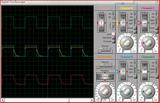
    I did some kinda research with virtual circuit in ISIS, 12V PSU, 0.5Ohm resistor acting to be a TEC (no matter for schematic TEC or resistor), 300Hz and 1Khz PWM at 50% pulse width, tried various capacitors, here u can see how does actual and PWM output voltage diagrams look like:


    1Khz 100uF

    1Khz 1000uF

    1Khz 10000uF

    300Hz 100uF

    300Hz 1000uF

    300Hz 10000uF


    Testing schematic:


    Personally I would suggest using 5000uF with 300Hz PWM and 1000uF with 1Khz.

    (does anyone know a good image hosting server with direct linking?)
    Last edited by Delfistyaosani; 08-01-2009 at 05:57 AM.


  21. #21
    Chasing After Diety
    Join Date
    Jan 2007
    Location
    Absolutely Speachless :O
    Posts
    11,930
    nice to see more people pondering on this concept.

    I figured since TEC's main advantage is the quick cycling of the on / off, if u had them on a controlled T-stat, couldnt you also save electricity and get sub ambient performance.

    Since ur unit is able to go down to 10C, a cycle on and off at around 15C im guessing would of be very nice on your electicity bill.

    That way when your coolant went over 15C it would turn on the TEC's, and as your coolant went below, the TEC's would turn off.
    Nadeshiko: i7 990 12GB DDR3 eVGA Classified *In Testing... Jealous? *
    Miyuki: W3580 6GB DDR3 P6T-Dlx
    Lind: Dual Gainestown 3.07
    Sammy: Dual Yonah Sossoman cheerleader. *Sammy-> Lind.*

    [12:37] skinnee: quit helping me procrastinate block reviews, you asshat. :p
    [12:38] Naekuh: i love watching u get the firing squad on XS
    Its my fault.. and no im not sorry about it either.

  22. #22
    Xtreme Member
    Join Date
    Oct 2008
    Location
    Canada
    Posts
    191
    It'd probably only work if the thermostat was actually a temperature probe that would control the duty cycle of the PWM. So that once it reaches a certain temperature it changes the duty cycle (sadly that means that temps will fluctuate by somewhat massive amounts). I also assume the most accurate way to measure the temperature is a DTS mounted to the CPU/Coldplate.

  23. #23
    Xtreme Enthusiast
    Join Date
    Apr 2008
    Location
    Auckland New Zealand
    Posts
    568
    The whole point of the T-Balancer and PWM booster is to set a coolant temp .. and it keeps it at that irrelevant of ambient temp or CPU load. So it saves you Heaps in electricity since you never run you PC at full load

  24. #24
    Xtreme Member
    Join Date
    Jun 2004
    Location
    Brighton, UK
    Posts
    131
    Quote Originally Posted by Ultrasonic2 View Post
    The whole point of the T-Balancer and PWM booster is to set a coolant temp .. and it keeps it at that irrelevant of ambient temp or CPU load. So it saves you Heaps in electricity since you never run you PC at full load
    Exactly Hard to see how a bang-bang controller would be more efficient energy-wise, and the slow duty cycle probably wouldn't do the TECs much good- PWM at > 300 Hz is what the manufacturers recommend
    EVGA Classified, i920 @ 4200 24/7, 3 x 2GB XMS CAS7, ATI 5870 FC EK W/C , Bequiet 850W PSU, XFi Music, Vista 64 Bit, peltier-chilled water-cooling

  25. #25
    Xtreme Enthusiast
    Join Date
    Apr 2008
    Location
    Auckland New Zealand
    Posts
    568
    well the T-bB switches at 820hz

Page 1 of 2 12 LastLast

Bookmarks

Bookmarks

Posting Permissions

  • You may not post new threads
  • You may not post replies
  • You may not post attachments
  • You may not edit your posts
  •