

Greeting, all.
I had purchased a Foxconn MARS(P35) MainBoard weeks ago. Planing to mod caps with high frequency caps to improve OC ability.
Solid Caps
As I know, the voltage indicate DC power for CPU, RAM & chipsets.


Greeting, all.
I had purchased a Foxconn MARS(P35) MainBoard weeks ago. Planing to mod caps with high frequency caps to improve OC ability.
Solid Caps
As I know, the voltage indicate DC power for CPU, RAM & chipsets.
If those are Fujitsus, your mod may not be very useful. You can try replacing them with Sanyo OS-CON's, but I doubt you will see a dramatic improvement.
Code:ASUS Maximus II Q6700 ZIPPY GSM-6600P (G1) Ballistix PC6400 Sapphire HD4870
You are right, Super Nade. Fujitsu & Sanyo are Solid Caps in the same grade. I found a better one: Panasonic SP-Cap(Specialty Polymer), high frequency character is superior... You may check the spec: SP-Cap high frequency character
Mod step 2.
As voltage value, we can estimate the DC power supply for which IC.(ex.1.32V for CPU, 1.8V for DDR RAM.)
Important point: Cap's voltage range(ex. DDR RAM voltage may overclock up to 2.1V, thus Caps >2V is recommanded.)
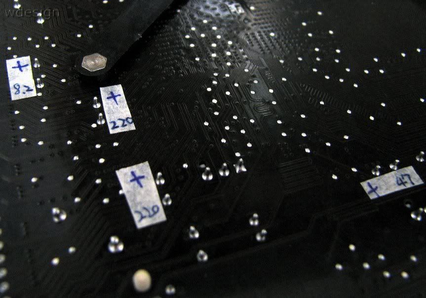
Mark cap locations with isolate tape.
Important point: Positive side.
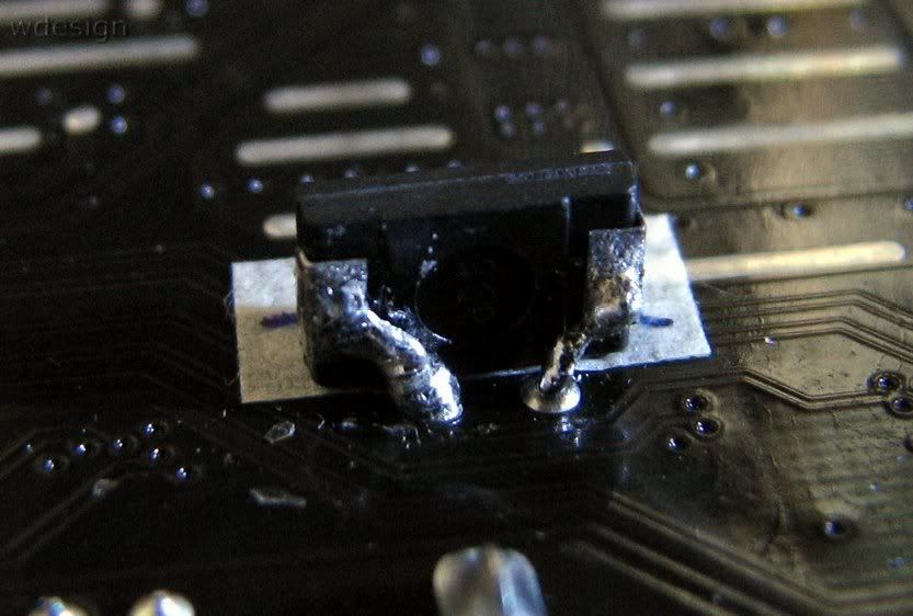
Caps for CPU = 2V/330uF.
Parallel soldering by original solid caps' DIP pin.
![Send a message via AIM to [XC] gomeler](images/misc/im_aim.gif)
Nice start, I want to do the same with a cheap board and see what'll happen with a little soldering. Wish you luck with your mod
wdesign, the ESR of those chip-caps does not seem to be in the milli-Ohm range? I don't think you can use them as a replacement to good OSCON's. But, you might be able use them in parallel with the OSCON. The idea is to have these chip-caps act as a high frequency shunt to ground (beyond say 500kHz).
One thing I'm concerned about is, in order for a high frequency shunt to be effective, it has to be as close to the CPU as possible. Now you already have rows and rows of MLCCs on the CPU package to take care of this. So, you see why I'm a bit skeptical?
Code:ASUS Maximus II Q6700 ZIPPY GSM-6600P (G1) Ballistix PC6400 Sapphire HD4870
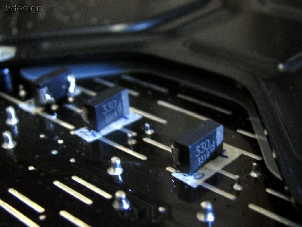
Hi, Super Nade. I did soldering them in parallel. 'casuse the PCB was designed for DIP caps, we didn't have SMD pad for SP Caps. Maybe you can have more confidence on chip-caps after looking following pcitures.
AnandTech: DFI UT P35-T2R: Tweakers Rejoice! <== Picture 2 & 3.
ASUS Blitz Extreme Mods ready to bench... <== 1st Picture.
Both of all caps for CPU are totally replaced by chip-caps. And they are State of the Art products by each brand company.
On picture #1, there is no inductor, so there is no need for OSCON type caps. Inductor ringing and the ripple current thereof is not a big problem (there are other types of problems though, i.e ones associated with a DAC/ADC). I don't know much about a fully digital VRM design, so I can't say much.
In any VRM design, the primary consideration or indeed the major role is that of the ESR and the ability to withstand inductor current surges. Check any single or multi-phase buck-regulator datasheet and that is what you would see. While the chip caps may have a very high inductor current rating, there is no info that I can see regarding its ESR (looks higher from your datasheet) or its leakage current?
Will it work?...probably, but certainly not for the traditional reasons a VRM design doc specifies. I'm not trying to say you are wrong, I'm just trying to understand why this is a better option than OSCON? Perhaps this is because of the way I work. I always have to know why and fully understand what is going on before I start changing things around.
Last edited by Super Nade; 11-20-2007 at 07:14 AM.
Code:ASUS Maximus II Q6700 ZIPPY GSM-6600P (G1) Ballistix PC6400 Sapphire HD4870

very exciting project you have there. Looks forward to see some result
OCTeamDenmark Crew - Cooled and sponsored by CoolerKit.dk
I love them modsTantalum caps just by its own not so good for CPU as it looks on paper, but in parallel to boost current caps is a great way to use them, more than enough
Keep pushing it.
 Posting Permissions


 Reply With Quote
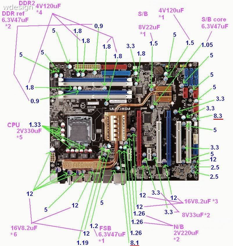
Bookmarks