


cka3o4nuk - G does not indicate "ground" it indicates "gate" as in drain, source, gate (terminals of FET) you will have to use a multimeter to find a suitable ground. As for the other pin just make sure it is attached to pin 15 of the controller chip.

 Reply With Quote


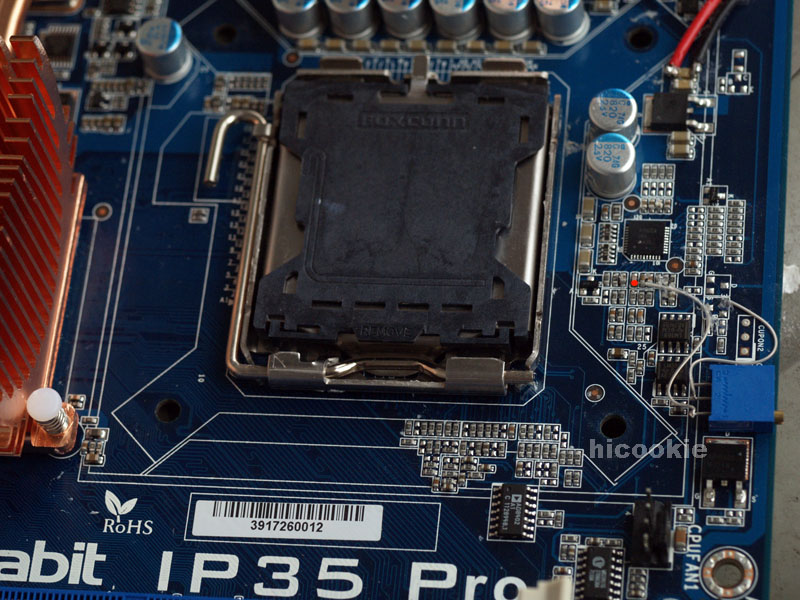


 , but one question. The red dot at the rt in the pic, is that referenced to ground? Because that is what I get at that point with my fluke, .3 ohm to the case. I was having a hard time getting the wire to stick on that point and finially gave up but now I get post code 8.7.and it won't continue past that
 I didn't get any solder across the contacts.


Bookmarks