

Ok, I have stayed up all night doing mods and I have only done 2 mods so far! Man, I'm slow. But hopefully I will finish in a day or two and I will post some photo's of my xtreme max3


Ok, I have stayed up all night doing mods and I have only done 2 mods so far! Man, I'm slow. But hopefully I will finish in a day or two and I will post some photo's of my xtreme max3
Hello
There is a modded BIOS 26 for IC7 here for those who are interested.
Regards,
pokipoki
Hello Hypro and everybody else, I am new to these forums although I know some of you well from other forums.Originally Posted by hipro5
I have the following droop problem on an IC7MAX3 with P4 3.2E (SL7CK) @ 4010 MHz, Using twin PSU's, one only for mobo ATX cons(Enermax 465W with 33A 12V rails:
My chip need 1.52-1.54V Vcore under load to run stable at this speed. In order to reach this minimum I have to set Vcore in bios to 1.58. The droop on the 12V ATX con is only 12.17 - 12.08. Will this mod help stabilize towards idle=load? Also, does this mod work on my mobo?
Thank you for answering. I use various mods from yr great guide, under which the Vcore caps mod, and the 12V xtra input choke mod.
This mod is only if you want to get higher VCore than the Mobo can supply.....I don't think though that you accualy have VCore droop problems as for IC7 series mobos......Measuring with a multimeter is the best to find out that......
INTEL PWA FOR EVER
Dr. Who my arss...
.........
I know, I always measure everything with a DMM, even the temps. Now, The droop I am writing about is actual droop, measured with DMM. Sorry I forgot to mention that. I already got rid of 0.12 droop that I had on my ATX cable, by replacing it with a higher gauge type cable. The droop is measured accross the extra caps soldered on the back of my board. They actually helped reduce droop a little.
i have done 3 mods on my max 3 agp ,vtt and vdd
they all work but that does not mean am getting more mhz out of it
so for the only mod that did wonders for me was the vtt mod
agp and vdd didn't help me at all
i have to say i only tested the board on air so far
gonna slap the prom on this weekend and see how far i can get
i also wanna do the capacitor mod but havent found the right capacitor yet
il keep u guys updated how she does under the prom
dfi rdx 200 -- 4000+ -- x1900xt -- 2gb g-skill pc4000
i think this might be my problem then.i got a friend to do all the mods.tried starting and nothing.its like the psu fans try to start but no go.which trimmer du i have to adjust?the vtt or ?hopefully the board aint dead.
Gigabyte X38T-DQ6/2x1gb xtreme/2x2900xt
E6850@ 4500
1000w psu/vapo Ls/2x74gb raptor raid.
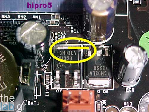
which mosfets went down.thats what happenned to me testing a 3.2e@3.8 with prime.would appriciat a photo of there location.i let it run overnight and next morning the comp was off.tried restarting but it couldnt.any clues to what happened.tried testing all the other hw and they work.i thought it was the ram mod that did it.couse im not so good in soldering.and as soon as i tried touching the wire on the mod it came off.so i sent it to a guy who fixed the mod and put all the other mods on while he was at it.got it back tried to boot and nothing.like the psu tries to start but fails.please help
Gigabyte X38T-DQ6/2x1gb xtreme/2x2900xt
E6850@ 4500
1000w psu/vapo Ls/2x74gb raptor raid.
can u mesure agp voltage with multimeter? try not to go above 1.95v
make sure the trace cut for agp mod is done right , my board was behaving strange because cut wasn't done properly
check this with multimeter to be sure
dfi rdx 200 -- 4000+ -- x1900xt -- 2gb g-skill pc4000
ill have to buy a multi meter,thanks
Gigabyte X38T-DQ6/2x1gb xtreme/2x2900xt
E6850@ 4500
1000w psu/vapo Ls/2x74gb raptor raid.
Hi guys!
I'm gonna do the vcore stablization mod just after doing the vdimm mod. I cannot solder the capacitor's on the back of my IC7 because i would not be able to put it back to my case. My friend told me to do it another way but i'm not sure if he is right. Please check this out
The whole thing is about unsoldering one of the capacitors from the mobo and connect some extra like this www.gorajec.net/Adasi/mod_eng.jpg .
cut a hole in the case so it will fit
dfi rdx 200 -- 4000+ -- x1900xt -- 2gb g-skill pc4000
Yes i know that's the easiest way but the reason i want to do it another way is that i don't want to cut my case again
hi, I did the VTT mod but not tested yet.
I have a question... how can I verify that the trace is successfully cut?
thx
any clues to #284
Gigabyte X38T-DQ6/2x1gb xtreme/2x2900xt
E6850@ 4500
1000w psu/vapo Ls/2x74gb raptor raid.
Where burned the two SMALL Mos-Fets - drivers - of the big ones for the VCore near the socket.......There are four small and four big ones for it......
INTEL PWA FOR EVER
Dr. Who my arss...
.........
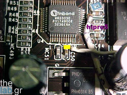
You can verify that the trace is cut by measuring from the two Mos-Fets - the ones that we measure the VTT - to the Capacitor of the picture I've posted........You sould measure NO contact......If you measure 0 Ohms then retry to do it......
INTEL PWA FOR EVER
Dr. Who my arss...
.........
i have done vtt mod ,agp mod and vdd mod and i dont seen to get the system stable over 265 fsb am using a 3.0c mach 2 cooled vdd set @ anything above 1.6v results in a worse oc vapg mod didnt seem to help me ,vtt helps me to get my b5 over 240fsb 1:1 @ 3.2v am using 2x512 sticks mushkin lv 2
@ 265-270 fsb am able to boot into windows but after a few minutes screen goes black aand computer reboots whatcould the problem be?
my 3.0c maxing out @ around 4000mhz????
dfi rdx 200 -- 4000+ -- x1900xt -- 2gb g-skill pc4000
ok so i've to measure here:

and... what capacitor?
thx for your time
Yes..........and on those spots
Here.......
...........and here........
..........after the cuting you should measure at those two spots NO conectivity..........NOT 0 Ohms......
Last edited by hipro5; 11-22-2004 at 04:13 AM.
INTEL PWA FOR EVER
Dr. Who my arss...
.........
Try to max your VAGP at - let's say - 1.8VAGP - and put into bios those settings for BH-5 , BH-6 chips........
2 - 5 - 2 - 2 32M Auto(not too aggressive) Enhanced 5 (or 4 - more aggressive , you HAVE to put it 5 in case of 5:4) Enable and Enable(this last try it at disable as well).......
INTEL PWA FOR EVER
Dr. Who my arss...
.........
I do the Malve's mod... but i've a question...
look at the picture

is that correct?
now... the guide says that i've to put a 200ohms vr at 0 ohms ....
but what pin is ground? the #1?
i've to put the vr at 0ohms... but betwen what pins?
between #3 and #1 or between #2 an #1
thx again
0 Ohms at pin 1 and pin 2.........I hope that you have already cut the VTT trace though......
INTEL PWA FOR EVER
Dr. Who my arss...
.........
now if the vdd mod was to be taken off.would the mb still boot?which way do i have to turn the trimmers if i wanted everthing as standard (no volt rises)i ask couse maybe i can determen if the mb will boot at all.i have 5 trimmers at the time being and hopefully they are set wrong,cousing the mb not to boot.im also tring to determind if i burnt any of the mosfets!
Gigabyte X38T-DQ6/2x1gb xtreme/2x2900xt
E6850@ 4500
1000w psu/vapo Ls/2x74gb raptor raid.
Try to turn them from the GROUND to every spot of them at their maximux resistance..........Also try to remeasure the resistance between cutings......You should see the 10 Ohms resistor..........IF not try to resolder it again.........
INTEL PWA FOR EVER
Dr. Who my arss...
.........
 Posting Permissions


 Reply With Quote
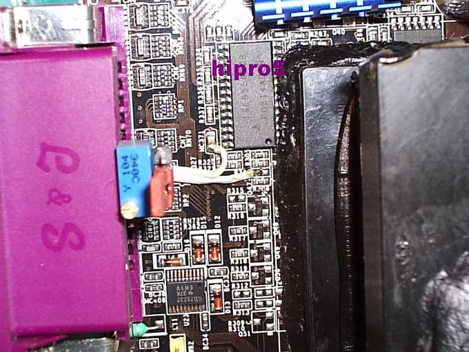

Bookmarks