


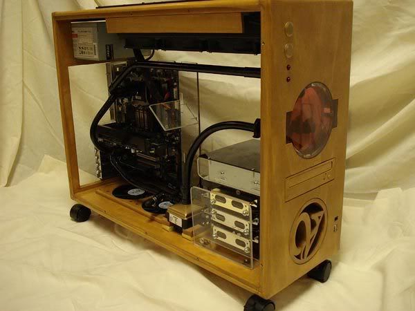
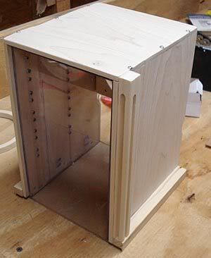
I have been building this computer case now for about a month, and have been posting a piece by piece build log on OCforums. I have decided to reword and post the log here on XS also as there are a lot of build logs posted here, but not many that involve a made from scratch case. Maybe in some way this will be a help to others here who would endeavor to undertake a project like this. This is the third wood case that I have made. The entire background and discussion of developing the model for this case can be found HERE, as well as the log for the second wood case which I am currently still using.
As anyone knows who watercools, cases designed for air take a lot of messing with to try to adequately adapt to water. This initially is what made me want to build my own case so that I could make the case to fit my setup, and to fit the desk compartment where it calls home. I have been very pleased with the second case I have built. It has served me well. However, there are a several improvements I have wanted to make to its design, and also, I am ready for a change.
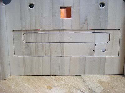
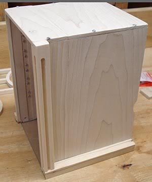
Although wiring is well hidden and managed, I want a way to be much more easily accommodate wiring as with my current case, it just barely fits in the space I allotted for it. This makes adding anything a bit cumbersome. I also wanted to get away from a top mounted radiator, and make the setup very easy to fill and bleed. In the appearance department, I want to get away from the current more boxy look and go for a more furniture, curved, fancy look.
I got a lot of great input while planning this build from a number of people on OCforums, several of which are also here on XS. I have spent probably 50+ hours working in Google Sketchup modeling this build. Being able to 3D model really allows you to fine tune your ideas and fit them together. Spending the time planning makes building much, much easier, and the end result much better. Also, modeling allows you to also incorporate how to actually construct the case and plan how to fit things together.
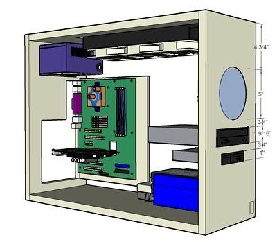
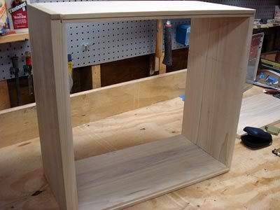
I started out with the base design that I used on my current case.
The problem I had is that I wanted to get away from the top mounted radiator, but a PA120.3 is so large that it is hard to position. I modeled several ideas for a bottom mounted setup, but each one of these presented problems that just didnt work for me.
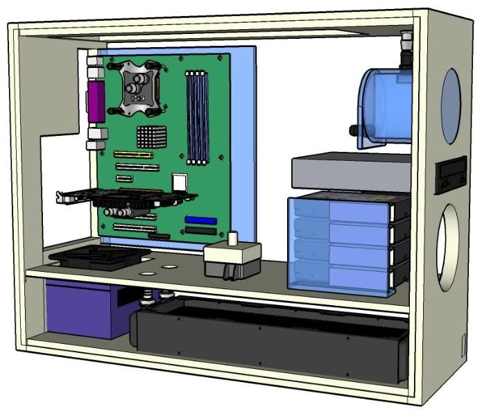
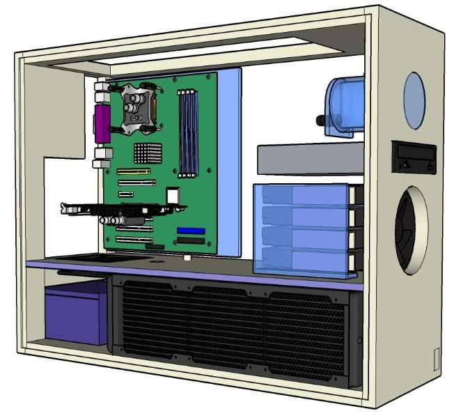
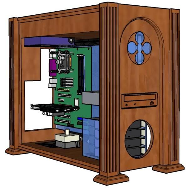
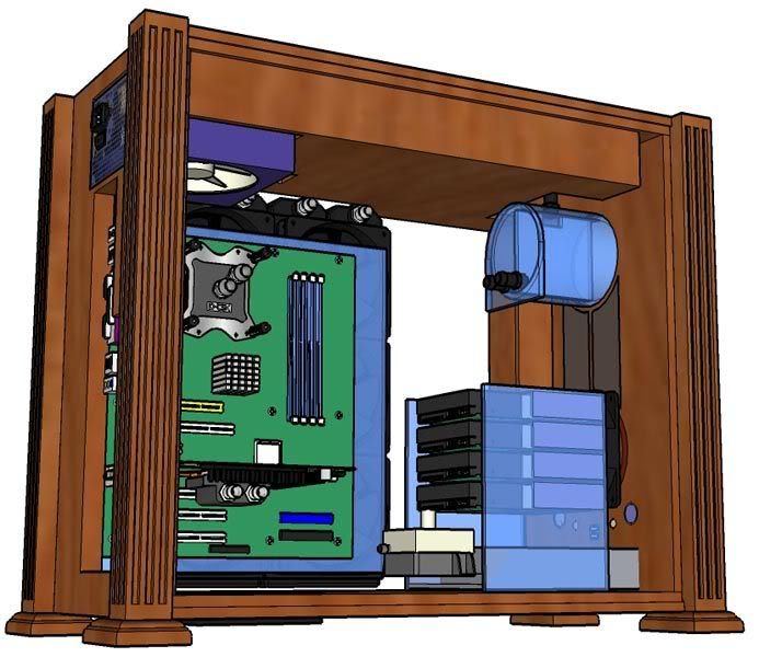
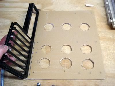
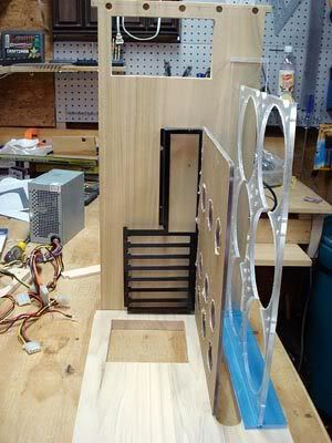
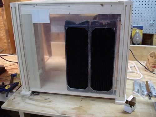
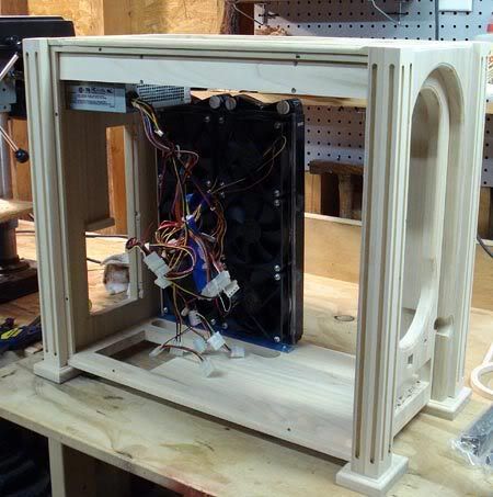
So then I played around with ideas still with a top mounted rad, but nothing really resolved my issues any better than the current setup. I came across a Magicool quad rad by accident on the performance-pcs website while looking at other stuff, and the shape of the rad gave me an idea. I saw that if I moved the motherboard over, the rad could be mounted behind it. I read reviews on the Magicool quad here on XS, and none of them were very good. So I next looked at Swiftech MCR rads. They are very thin and yet perform well, and are much smaller than the PA rads. I looked at going with 2x220 rads, but with there only being a $6 difference between the dual and triple, I opted for designing a way to incorporate 2xMCR320 rads.
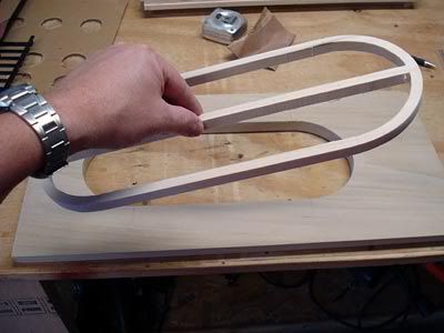
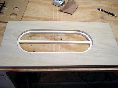
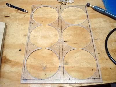
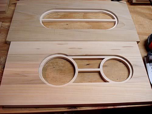
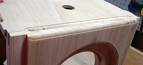
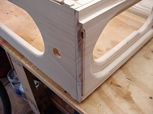
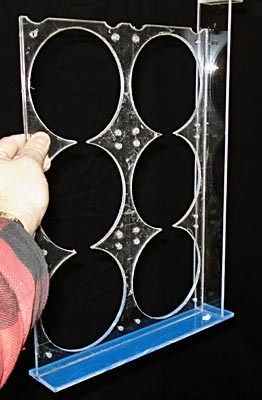
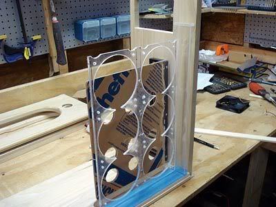
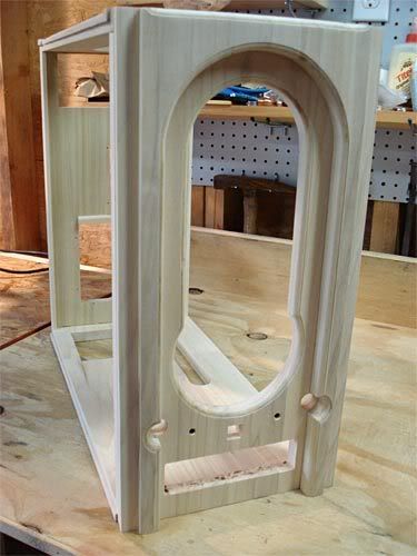
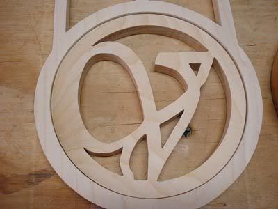
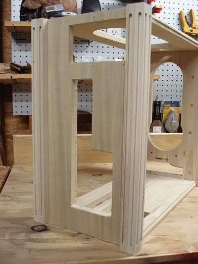
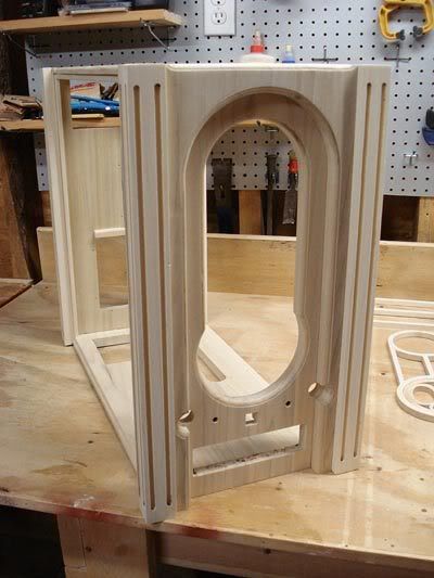
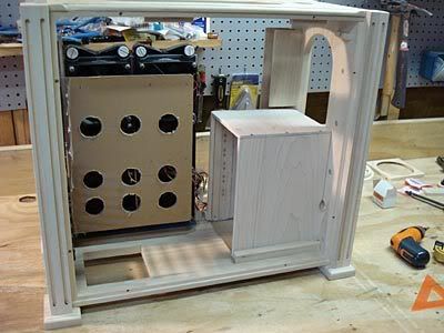
After looking around online for design ideas, I came up with this columns and clover idea, having seen the clover in some 1920s furniture and architecture.
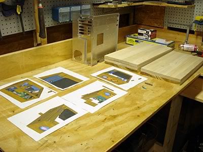
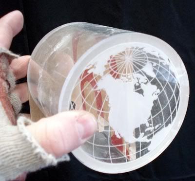
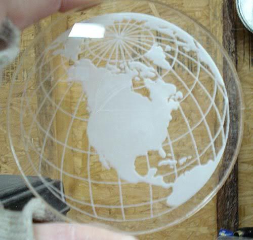
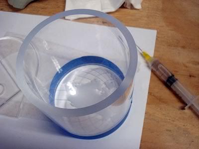
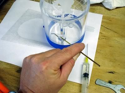
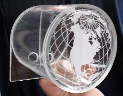
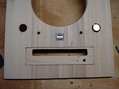
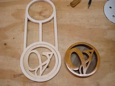
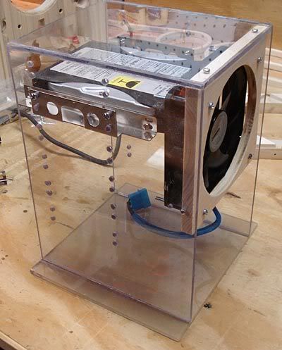
However, the clover would block some of the front of the new 4 dia res I planned on making. I used a 5 res in the current build, but wanted to go down to 4 so as to not make things quite so tight on the face. Blocking the front of the res wouldnt really matter if the face was just plain clear, but after a thread I posted on OC to see if anyone did any laser cutting so that I could get the front and back for the res cut, Dennis from Danger Den contacted me and not only cut the pieces for me, but also had the laser etch a custom graphic which I emailed him.

 Reply With Quote
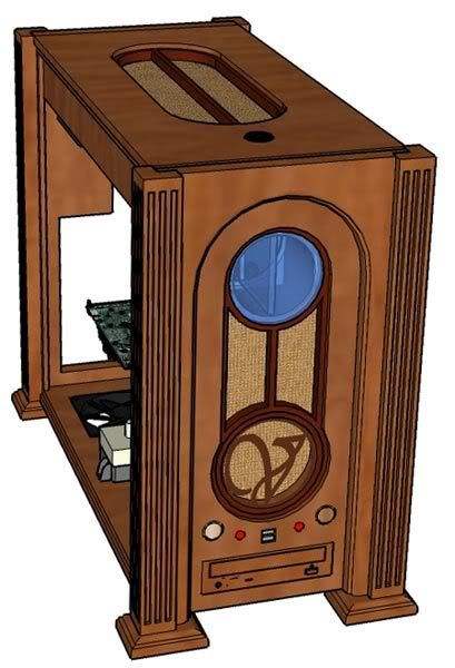


Bookmarks