Page 6 of 6 FirstFirst ... 3456
Results 126 to 134 of 134

Thread: Project Prism - A Lian-Li PC-v2000 Worklog

  1. #126
    Registered User
    Join Date
    May 2012
    Location
    California
    Posts
    96
    Looking more and more like my life is allowing for monthly updates... sorry for the long delay. I've worked little bits and pieces each weekend for a few hours at a time... so while I haven't shared in a while, at least I saved it up and have a large bit to share now! Anyway, on to the fun...

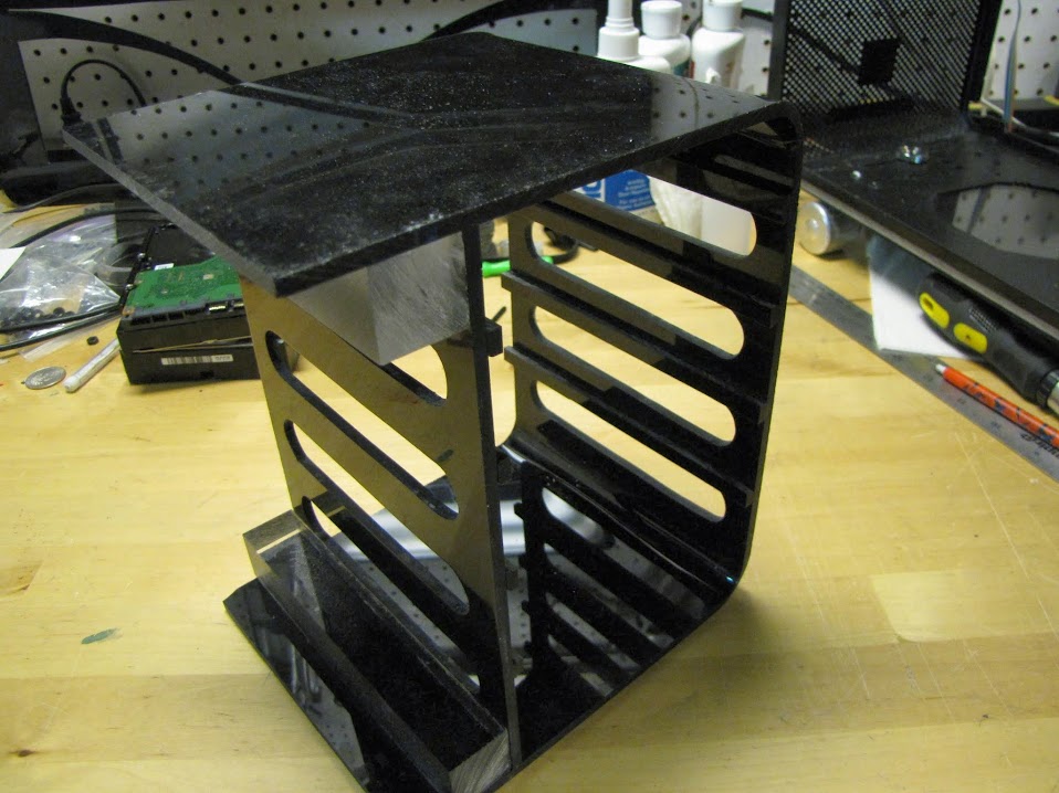
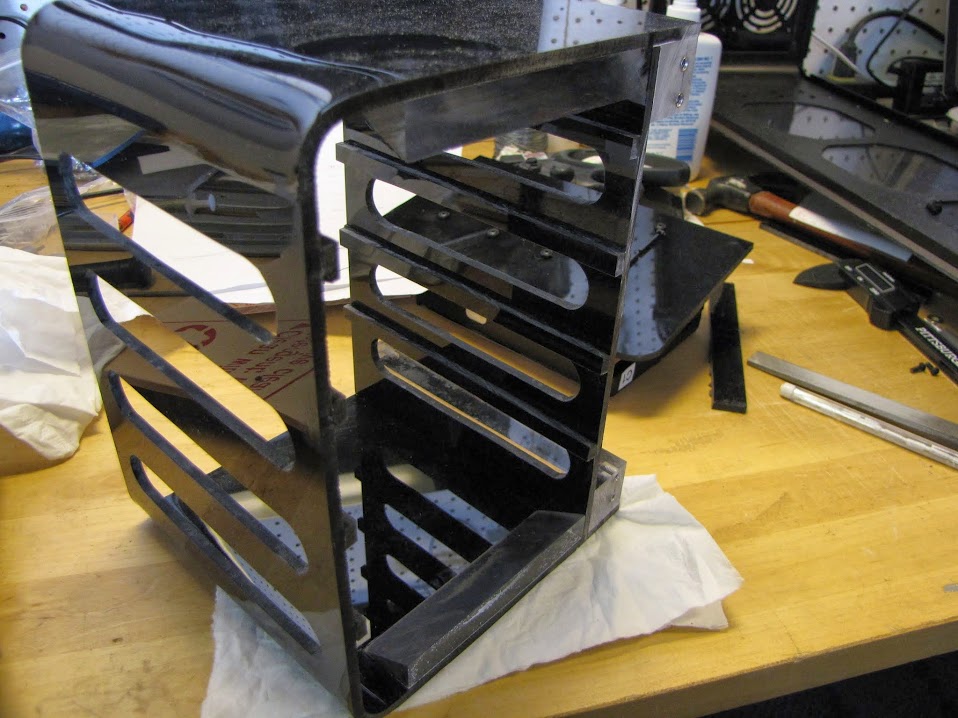
    Last we left the drive cage, I had cut and shaped most of the pieces, but they were just leaning together... nothing solid yet, and pretty rough. I decided the best approach would be to glue it together first, then use my dremel, sandpaper, etc to clean up some of the edges. Here it is with the inside wall glued in place, and the two supporting beams glued as well.


    The two clear beams will serve not only to strengthen the inside wall (without them, only the edges would be glued to the "U", not very much surface area for the kind of weight I would be putting on it...) but they will also be the mounting points that will attach the drive cage to my case... more on that later.

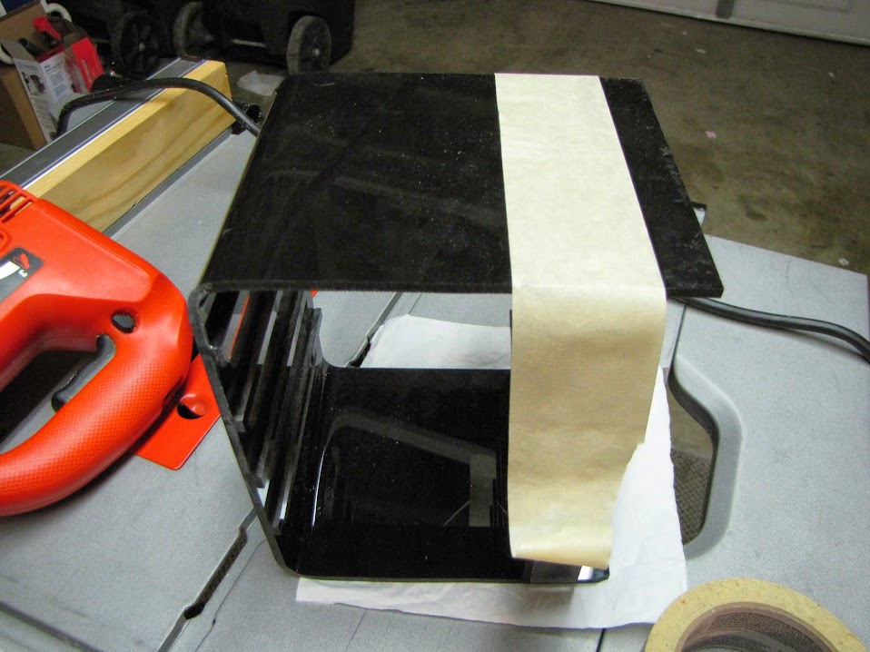
    With everything glued in place, I had some excess scrap to cut off the "U" (I left it intentionally, to give myself lots of room, as the measurements pre-bending were a little too hard to figure out on paper. ). I used some simple masking tape to mark the line I wanted to cut, then decided my jigsaw would be the best tool to cut off that edge. My table saw was a little too risky given all the work I put into the piece so far, and using a manual hand frame scroll saw would take ages.


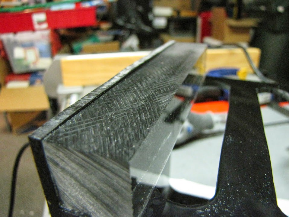
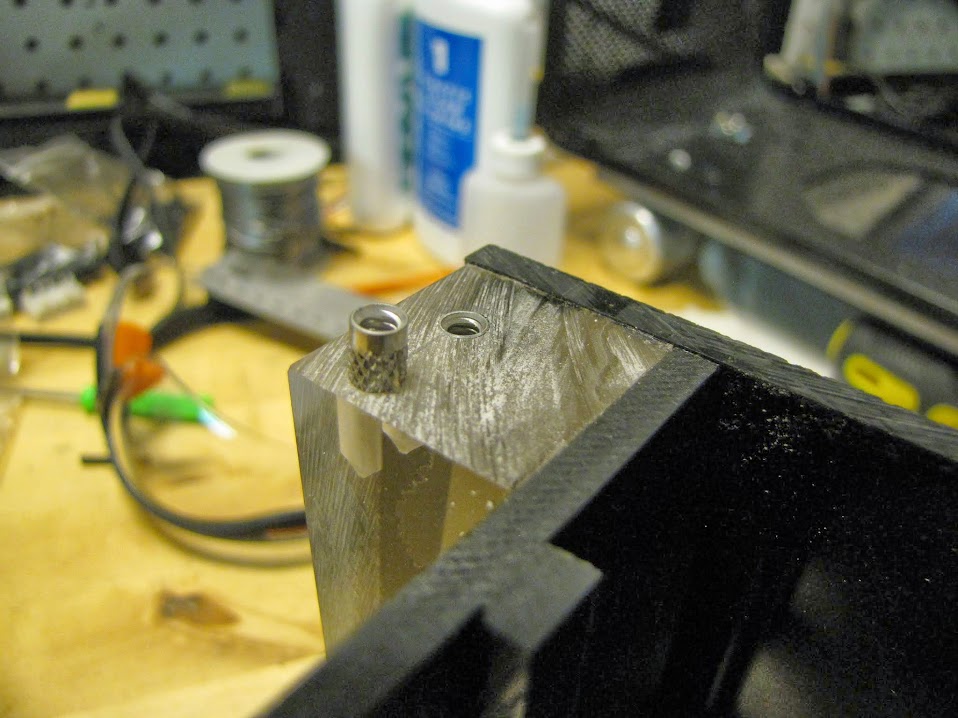
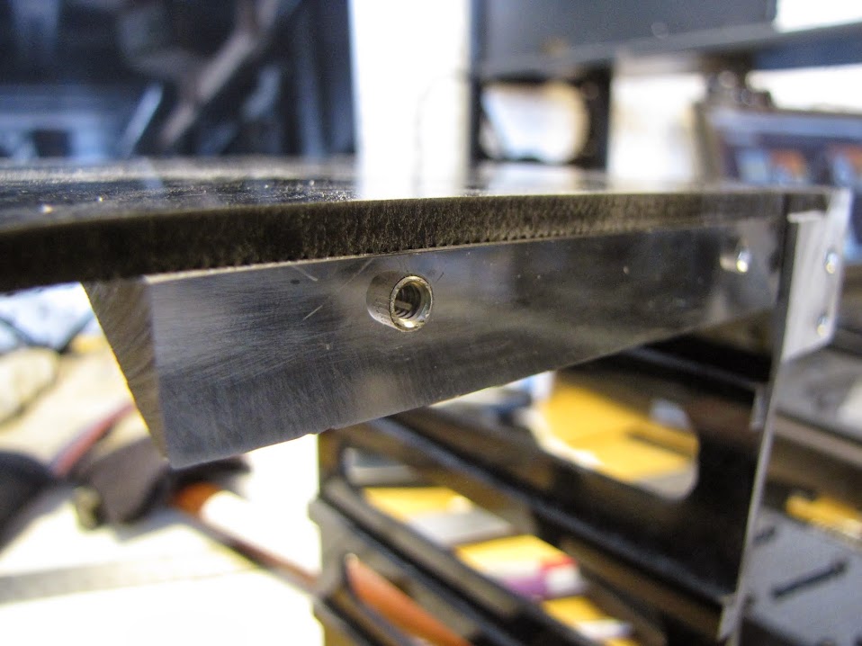
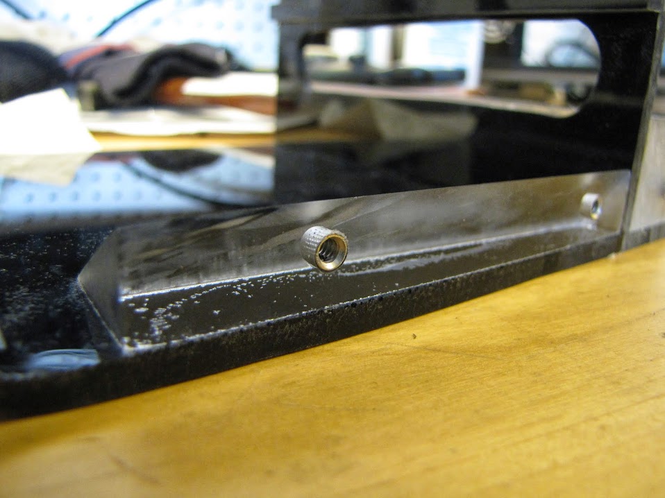
    I left just a bit of an edge, as I didn't want to accidentally cut into my support beams. I then went back over this edge with my dremel and a sanding drum attachment to grind it down nice and flush. Next, I moved on to drilling some holes in the support beams to seat more press-fit screw housings into, using the trusty old drill press:


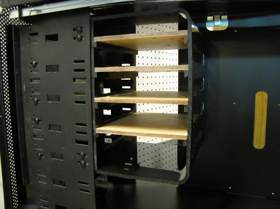
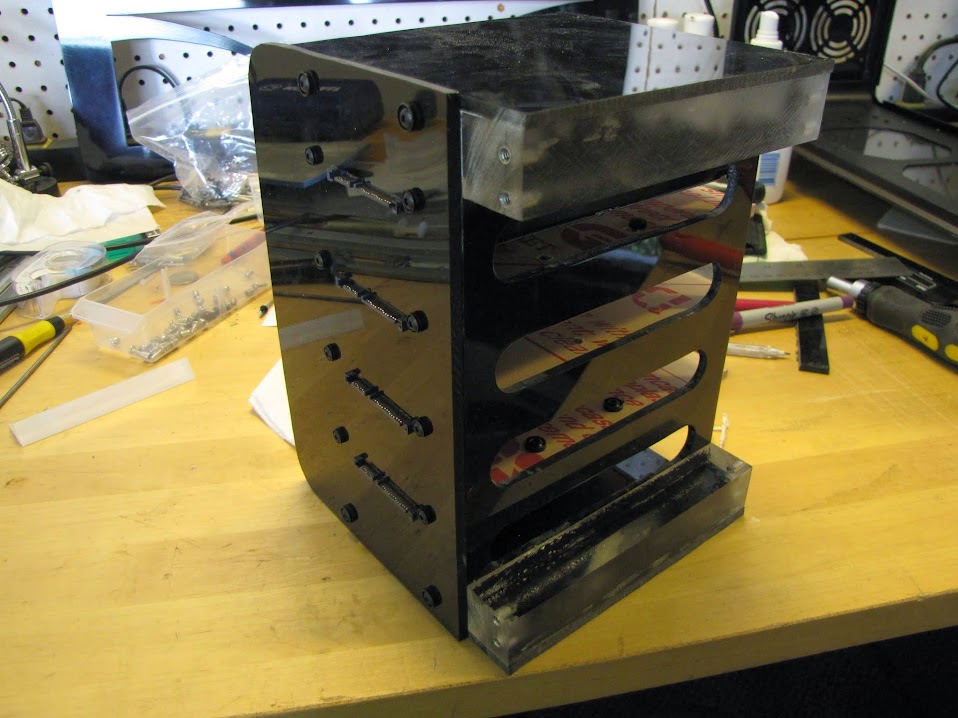
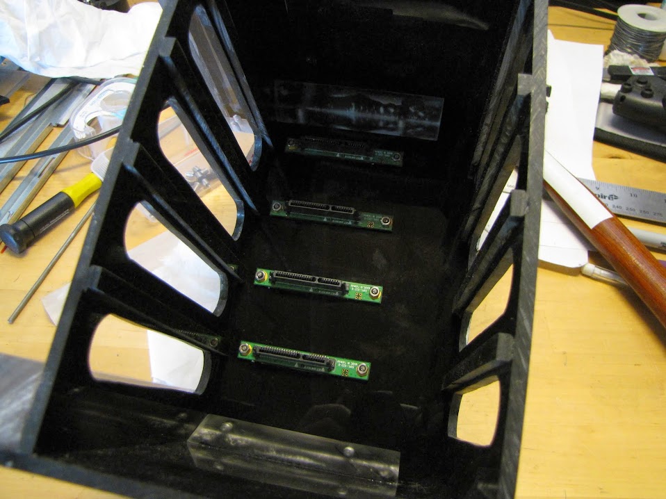
    Initial fit test, all screwed in and looking just fine!


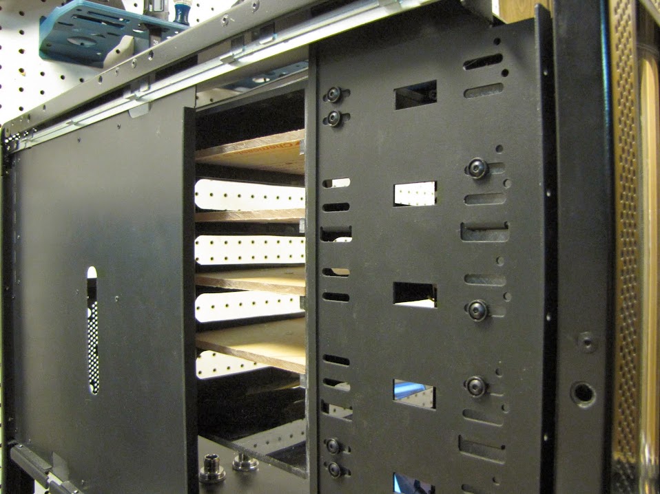
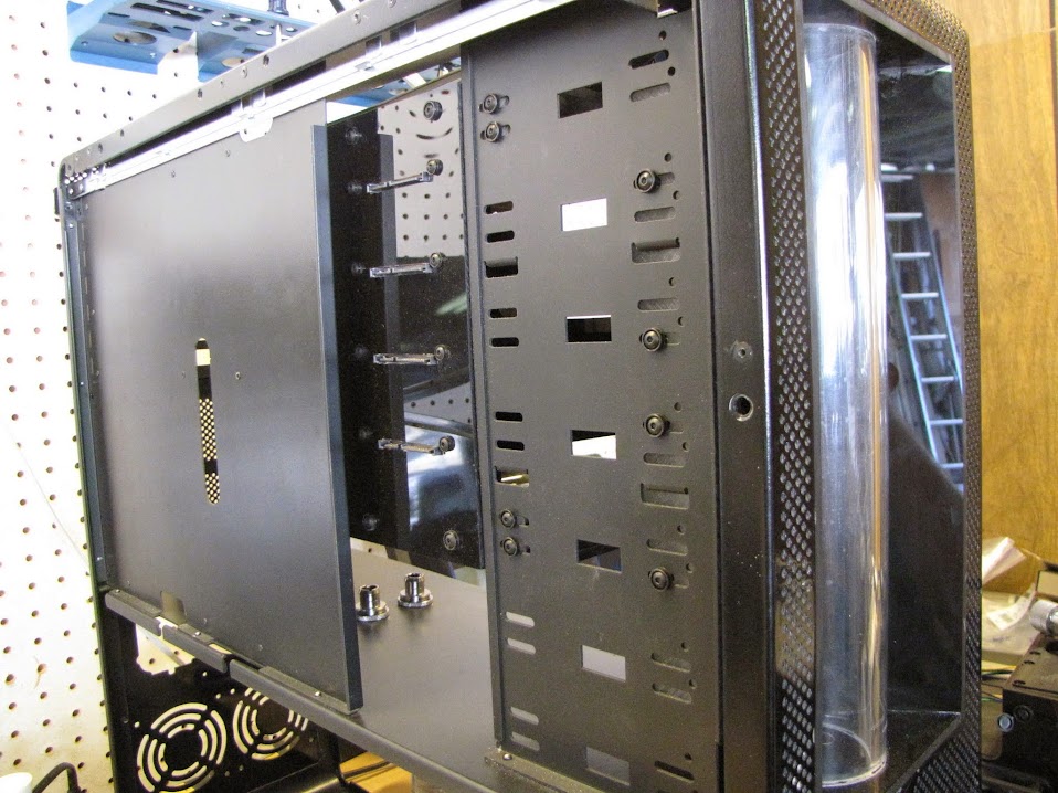
    And from the back side:


    Now, it's all screwed in, but it's still not much of a drive cage yet... time to get to work on planning the most important piece... the backplane!


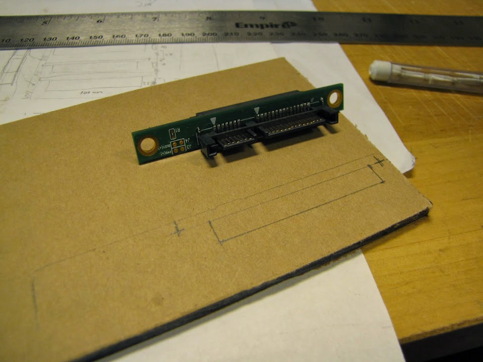
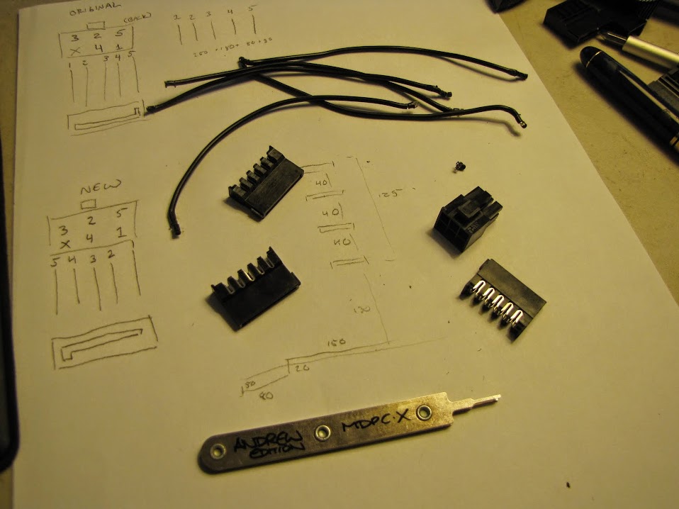
    First, I did quite a bit of measuring. Hours and hours of it, in fact. To get the drives to slide in nicely, I needed "sub millimeter" precision... the slightest bit to the left or right, and the drive wouldn't seat correctly.

    I ended up taking the approach of measuring it all out on a scrap piece, and giving the cut a few attempts, tweaking the measurements and re-cutting as I iterated through attempts. A little archaic, but it guaranteed a reliable/reproduce-able result in the end. Here is my first go at measuring out the cut points. In this first iteration, I was cutting out a block large enough to allow room for the connectors to stick through, along with all the pins, some of which you can see stick out of the PCB a bit, requiring room.


    After measuring it out a bit, I cut it out using the drill press to create some pilot holes, and the jigsaw to finish it off. The result...


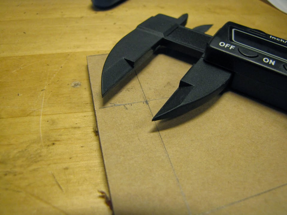
    Not so pretty. Fail. :o:p The Jigsaw proved too squirrely for these small parts, and the large cutout was not the look I was going for... I wanted something a bit cleaner looking. At this point, I decided to drop the old metal ruler, and go for my high precision digital calipers, with 'actual' sub-millimeter measurements!


    ... alas, I'll spare you the multiple additional iterations of attempts I made before I finally got the measurements and process right. :p

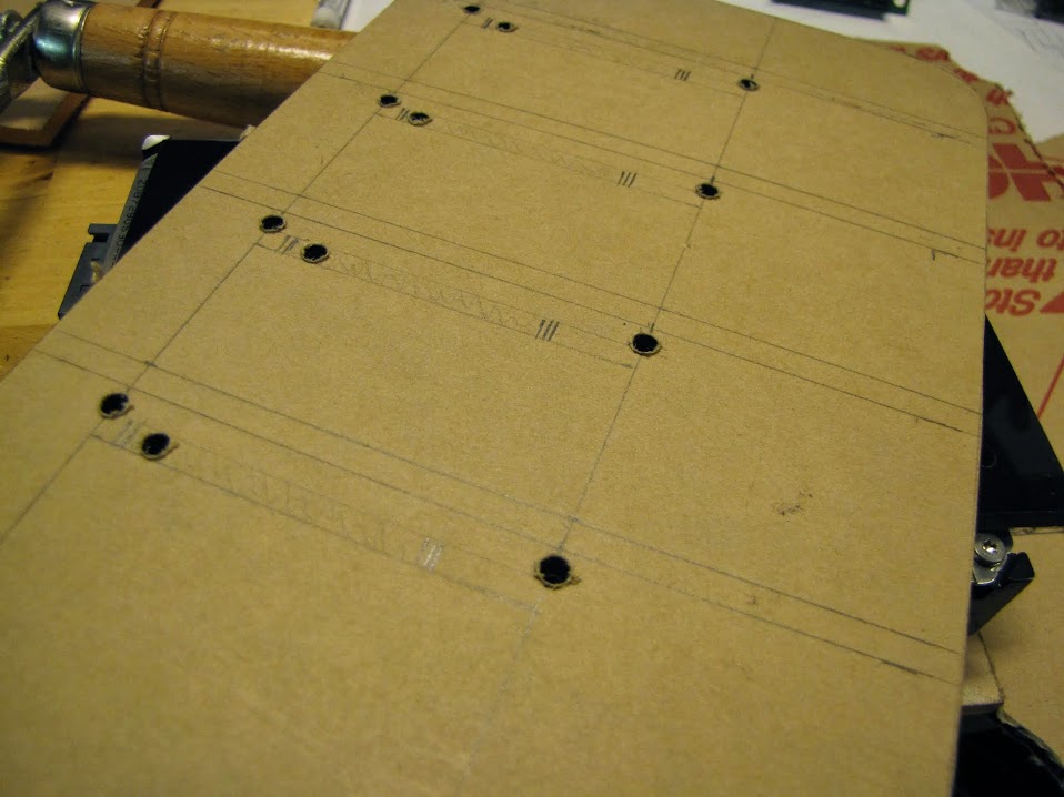
    Here's the final backplane, all measured and marked, with pilot holes cut, ready to finish the openings for the SATA passthrough ports:


    The biggest challenge in getting all this measured out was that the bays are not exactly perfectly spaced... one millimeter off here and there... which makes very little difference as I gave myself about 20mm of space between drives for slack... but makes a huge difference for the backplane, which all four drives need to seat against simultaneously. I measured and re-measured these lines more than 20 times... partly because I wanted them to be exact, and partly because at this point, I wasn't exactly sure how I wanted to proceed...

    I could use the hand scroll saw, which would take hours, but I would likely end up with a fairly accurate cut. A power scroll saw would be perfect, but I don't have one of them yet unfortunately...

    I could use my dremel with a cut off wheel... but the chance of messing it up would be pretty high, and the cut wouldn't be perpendicular to the surface of the acrylic, which would be pretty important for this high precision piece.

    I could use a hand router, but I didn't have any bits that would make this small of a cut. and I felt like it would be too overpowered/not precise enough at making straight lines.

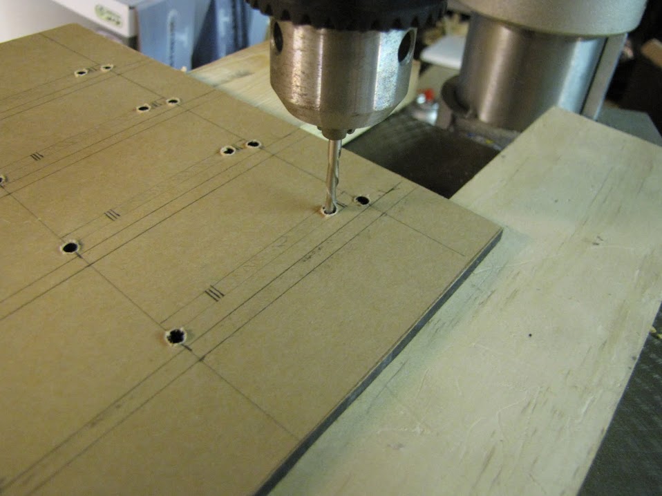
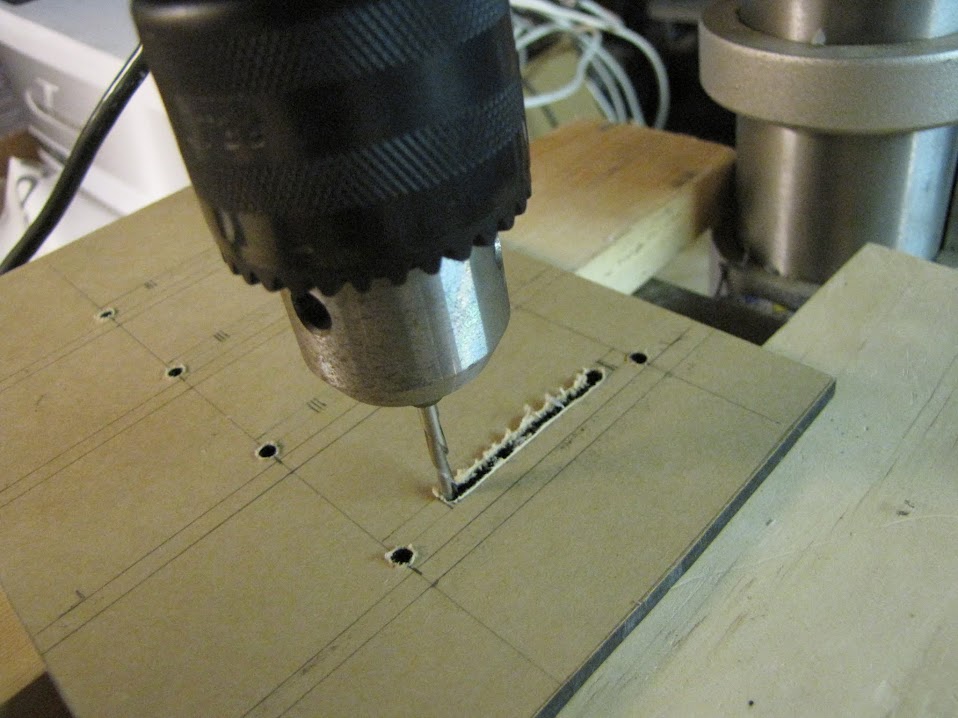
    I had a tiny router bit (a downward spiral bit) that came with my dremel, but I've never been able to get it to do a straight line correctly. Hmm... If only I had some way of using the tiny dremel bit, with a big machine that will hold perfectly steady. Then I came up with a wacky idea...


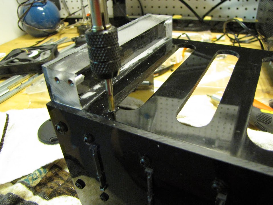
    Put the dremel bit into my drill press, and use it as some kind of hybrid table router / scroll saw! I cranked up the speed on my press to make sure that I was getting a very quick cut... the drill press wasn't made for this kind of "side to side" cutting, and my spiral bit has seen better days (not very sharp any more), so the extra speed helped make sure the lines were clean.

    Here it is after the first cut... works perfect!


    I went through and quickly finished the other four cuts, then broke out the hand file tools to clean up the edges and square everything out:


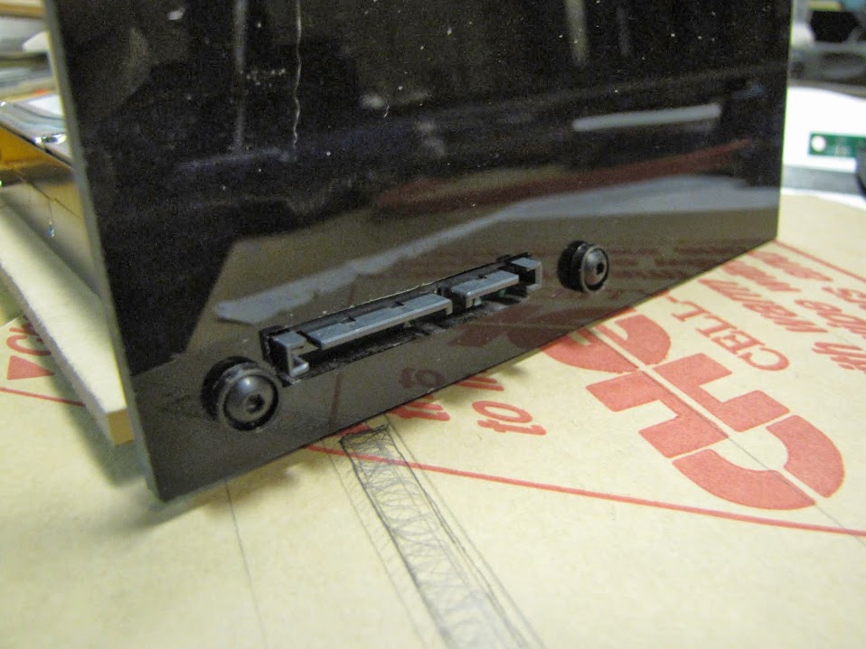
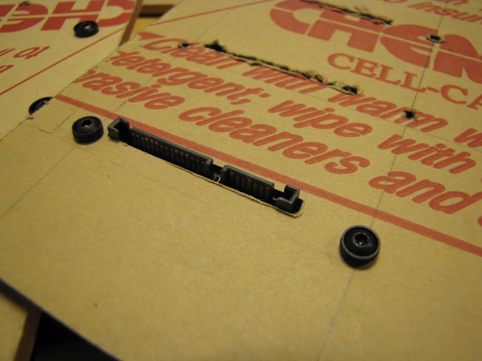
    Perfect! Nice clean opening, just wide enough for the connections to fit through without exposing any of the underlying PCB.

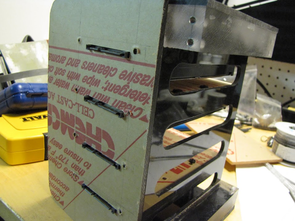
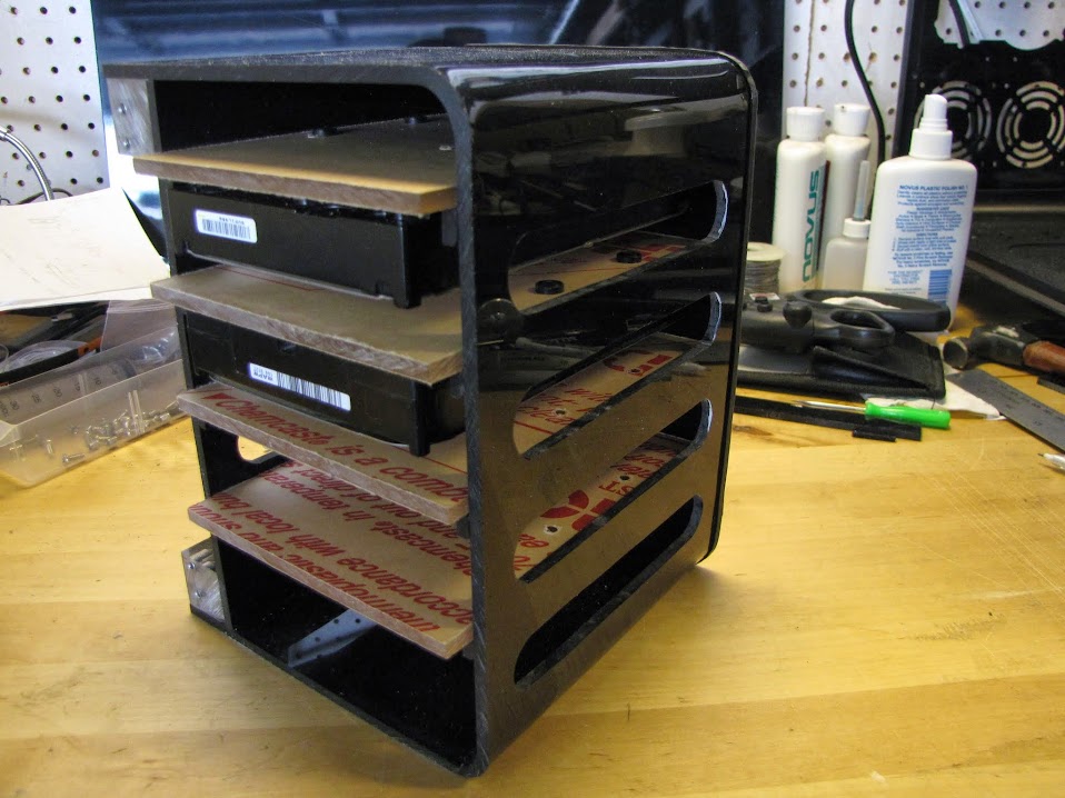
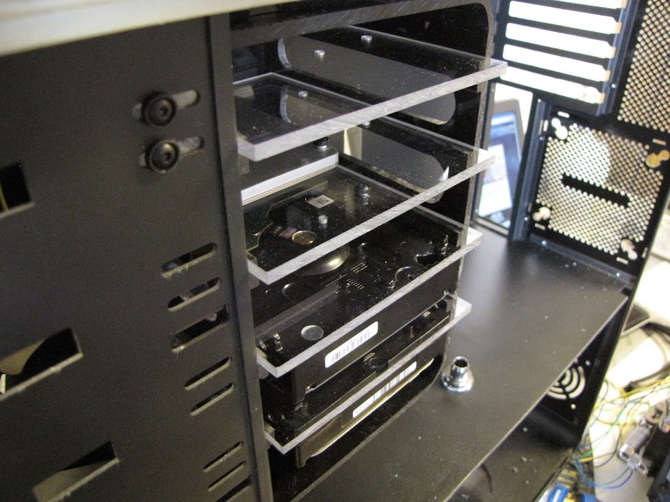
    Here we are with all four drive bays populated and slotted in!


    Again, perfect! SO glad it worked on the first try... would have been a lot of work lost if something got screwed up.

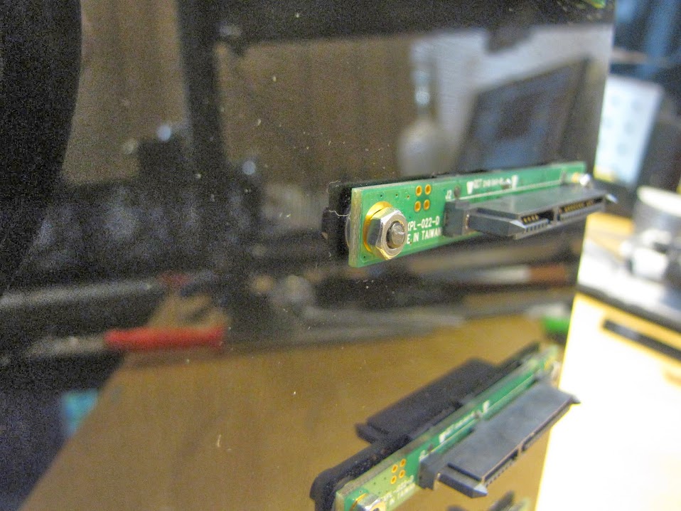
    After verifying everything roughly fit together, and using my filing tools for hours on end, I finally got to peel the backing off and assemble everything! I had to run down to the local hardware store and find some tiny washers and nuts that would fit the 6/32 MDPC screws I was using, then put it all together:


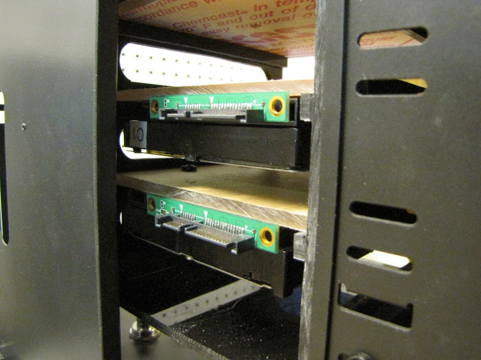
    You can see in the closeup below, I had to put two tiny washers between the acrylic and the backplane PCB... this was due to those solder points sticking off the board, mostly. With these, it floated nicely in place.


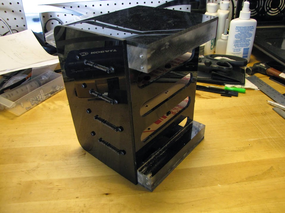
    Here it is quickly put together, for a "quality / progress" check:


    Getting closer!

    Next, I had to decide how I wanted to attach the backplane to the drive cage. My original thought was that I would glue it on... but I decided it would be way more useful if I could disassemble it when I needed to clean it or make modifications down the road. Well... disassembly means using screws, and the drive cage didn't have anywhere I could really seat my press-fit screw housings into... time to add a place! :p


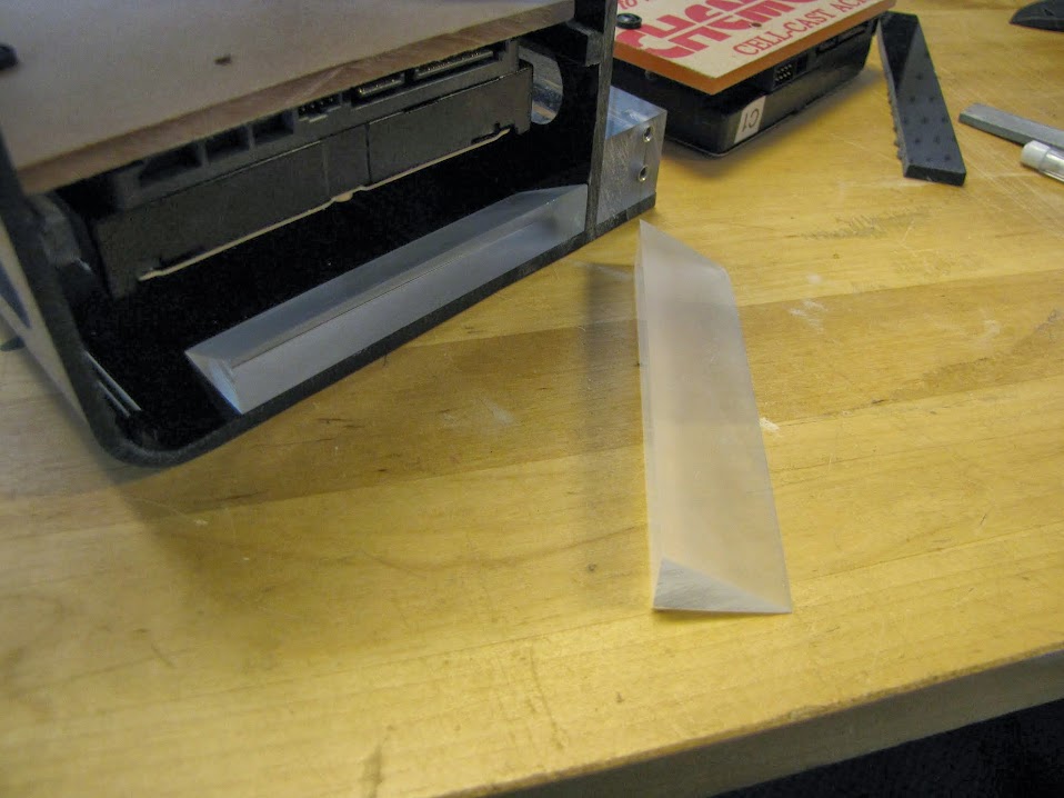
    I used a few remaining scraps of my 1" thick clear acrylic to cut some wedges for along the inside top and bottom of the drive housing. These would allow me space to drill into, so that I could drop some press-fit screw housings into them and screw the backplane on.

    Here we are post gluing:


    And with the screw housings drilled and pressed in:


    Huzzaw! All screwed together!


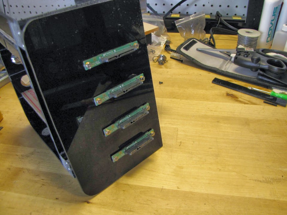
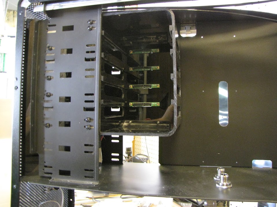
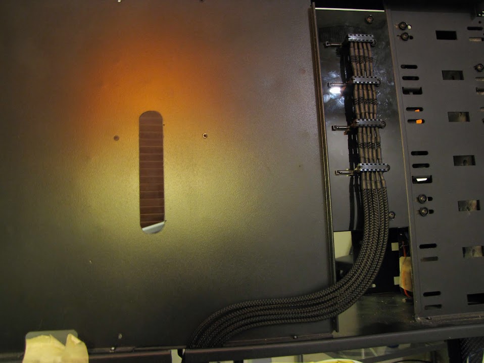
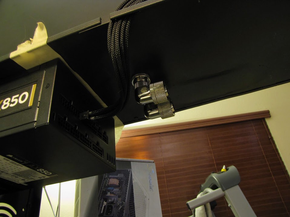
    And back in the case, for a final look:


    And finally, with the backing off of the drive plates:


    That's almost it for v1 of the drive cage! That's right... v1. There will be more... later... but I think I am happy with the functional version for now... I just have one more step (adding a fan for airflow... it's in the mail right now...)

    The flashy/added effect version will come in the future... hint... there's a reason the drive plates are made out of clear acrylic!


    Until next time!
    EVGA z77 FTW -- 16GB of Samsung MV-3V4G3D/US -- Intel Core i7-3770k -- EVGA GTX680 -- Corsair AX850 PSU -- Lian-Li PC-v2000b -- 2x XSPC RX480 Rads -- EK-RES-250 -- EK-DDC Dual Top/pumps -- EK-FC680EN Full Cover block -- Swiftech Apogee HD Block

  2. #127
    Registered User
    Join Date
    Nov 2008
    Posts
    55
    exceptional work , looking good man !

  3. #128
    Registered User
    Join Date
    Oct 2006
    Location
    Upper Midwest, USA
    Posts
    93
    Following with interest as I have a V2000 myself and it is going to be upgrade time soon. I may steal a few ideas.
    HARDWARE
    CPU: Intel i7-6700K - Delided and repaste w/Liquid Metal
    RAM: 4x4GB Kingston CL15 3000
    MB: Gigabyte Z170x-UD5-TH
    GPU: *Waiting for Vega*
    AUDIO: M-Audio Firewire Audiophile
    HD:
    *waiting for NVME drive*
    1x512Gb Samsung 850 Pro
    2x150Gb Raptors RAID 0
    PSU:
    EVGA 850 P2
    Meanwell 320w-12(Running 13.4v for pumps)
    MNT:Acer 2423W & HP ZR24W

    COOLING

    CPU: Swiftech Apogee GTZ
    GPU: *SOME WATERBLOCK FOR VEGA*
    RAD: BlackIce III Extreme
    PMP: 2xLang D5 in series
    TUB: 1/2" ID (3/4" OD) Tygon Silver Antimicrobial
    FANs:
    3xDelta EFB1212SHE TriBlade
    2xSharktoon SK-2000-80
    2xCM Excalibur
    1xDelta GFB1212VHW

  4. #129
    Registered User
    Join Date
    Apr 2013
    Location
    California
    Posts
    35
    How are the drive plates fastened to the cage? Is it just friction from self-weight and the resistance from the SATA connectors?

  5. #130
    Registered User
    Join Date
    May 2012
    Location
    California
    Posts
    96
    Quote Originally Posted by dietje1908 View Post
    exceptional work , looking good man !
    Thanks!


    Quote Originally Posted by Baenwort View Post
    Following with interest as I have a V2000 myself and it is going to be upgrade time soon. I may steal a few ideas.
    Steal away, I'm sharing my process for a reason. Feel free to hit me up if you need any in-depth info / schematics!


    Quote Originally Posted by Lord Brand View Post
    How are the drive plates fastened to the cage? Is it just friction from self-weight and the resistance from the SATA connectors?
    Yes, actually! I planned the two side rail walls to be tight enough that the friction of the drive plates against the walls actually keeps the drives in place, even when the whole cage is tilted almost 90 degrees on it's face. I obviously don't plan on laying the case on it's face... so they should stay put for the most part. The SATA connectors are also fairly tight.

    That said, I did actually have a potential planned modification to the drive cage that I haven't decided if I will move forward on or not... I was thinking of drilling some pinholes in the acrylic on the backplane that line up with the drive plates, then drilling and tapping a corresponding hole in each drive plate... then I could just feed a screw through the backplane into the drive plate to secure it against the backplane. I may end up implementing this when I go back over the plans for V2 and include the lighting etc. The tricky part is that the lighting would be exactly where the "set screw" would be located so that it could feed light directly into the drive plate... I may be able to locate the set screw off towards the edge though to keep it out of the way of the LED strips... or put one on either end. We'll see.
    EVGA z77 FTW -- 16GB of Samsung MV-3V4G3D/US -- Intel Core i7-3770k -- EVGA GTX680 -- Corsair AX850 PSU -- Lian-Li PC-v2000b -- 2x XSPC RX480 Rads -- EK-RES-250 -- EK-DDC Dual Top/pumps -- EK-FC680EN Full Cover block -- Swiftech Apogee HD Block

  6. #131
    Registered User
    Join Date
    Apr 2013
    Location
    California
    Posts
    35
    Two follow up questions/suggestions.

    Why not pin hole and thread insert at the side instead of the back? Decent black anodized thumb screws should be fairly easy to source.

    RE the light kit, tell me the LEDs for each plate will indicate the respective drive activity?

  7. #132
    Registered User
    Join Date
    May 2012
    Location
    California
    Posts
    96
    Quote Originally Posted by Lord Brand View Post
    Two follow up questions/suggestions.

    Why not pin hole and thread insert at the side instead of the back? Decent black anodized thumb screws should be fairly easy to source.

    RE the light kit, tell me the LEDs for each plate will indicate the respective drive activity?
    RE: the pin hole location... the only reason I was going for the back was to keep the side with the vents "clean" looking, as I liked the glossy appearance. If I can't figure out how to get the back to jive right, the side is indeed the 'fallback' option.

    Re: the light kit... you know it will. Arduino ftw.
    EVGA z77 FTW -- 16GB of Samsung MV-3V4G3D/US -- Intel Core i7-3770k -- EVGA GTX680 -- Corsair AX850 PSU -- Lian-Li PC-v2000b -- 2x XSPC RX480 Rads -- EK-RES-250 -- EK-DDC Dual Top/pumps -- EK-FC680EN Full Cover block -- Swiftech Apogee HD Block

  8. #133
    Xtreme Addict
    Join Date
    Jun 2005
    Location
    Madison, WI
    Posts
    1,004
    Those drives will be nice and snug!
    \Project\ Triple Surround Fury
    Case:
    Mountain Mods Ascension (modded)
    CPU: i7 920 @ 4GHz + EK Supreme HF (plate #1)
    GPU: GTX 670 3-Way SLI + XSPC Razor GTX670 water blocks
    Mobo: ASUS Rampage III Extreme + EK FB R3E water block
    RAM: 3x 2GB Mushkin Enhanced Ridgeback DDR3 @ 6-8-6-24 1T
    SSD: Crucial M4 256GB, 0309 firmware
    PSU: 2x Corsair HX1000s on separate circuits
    LCD: 3x ASUS VW266H 26" Nvidia Surround @ 6030 x 1200
    OS: Windows 7 64-bit Home Premium
    Games: AoE II: HD, BF4, MKKE, MW2 via FourDeltaOne (Domination all day!)

  9. #134
    Registered User
    Join Date
    May 2012
    Location
    California
    Posts
    96
    It's been so long! Time flies when you're having fun I guess.

    Life has been busy, as always, but I've been fortunate enough to get pockets of time here and there to make some progress. I've piled up a few pictures, so it's time to share!

    First, as indicated last time, I went ahead and purchased a fan to install on the back of my hard drive cage. It took quite a bit of research to find one that would fit considering the tight space, but I located a nice low profile 140mm fan that fit. I thought about a few ways to attach it, but decided to settle on simply tapping a few holes in the back of my drive cage, so that I could screw it flush against the surface. The area is completely invisible once the cage is in place, so I could have duct taped it on for all it mattered, but this 'felt' nicer.


    Unfortunately, all the pictures of the cage assembled with the fan seem to have become corrupt, and my drive cage is now assembled and in use in the case... so no pictures for now... but the next time I get it apart I promise I'll share! :p

    Next, I decided to move on to some sleeving, at last! I started with the pumps, since they seemed pretty easy... just two sleeves each. Well... it wasn't as easy as I thought. I did an initial sleeving with the shrink just running up to the pump... but it didn't look right, and you could see a bit of the colored wires where the sleeve met the pump. Time to take it apart!


    The second attempt looked much better. The shrink is a bit crinkled up by the pump, but I'm not so sure there's anything to do about that... the hole in the pump housing is very tight, and practically crimps the wires by themselves, not to mention when they are shrinked. Not bad otherwise though, I'm pretty happy with it, for my first shot at sleeving.


    Next, I decided to make myself a custom USB to 4-pin motherboard header cable. This will run from my motherboard USB header down to my arduino hiding under the radiator housing, which will control my pumps/fans/etc. I started by disassembling an unused USB bracket, and cutting off the header portion of one of the cables.


    Next, I took a regular old USB printer cable and cut off the "A" side of it, then stripped the wires:


    A quick bit of soldering and a little electrical tape later:


    I then proceeded to shrink over that part of the cable to tidy it up, reattached the USB header, and shrinked the head for good measure.


    I didn't think to sleeve this cable, especially since it will be completely hidden... but maybe I'll go back and sleeve it anyway, just for the heck of it, if I have some spare sleeve left over. I could also go as far as buying an empty USB header and some shielded USB cable, and cut myself a completely custom cable, but I digress... I have many other important things to get to first.

    Next, I decided to move on to sleeving some of my PSU cables. Many of these were nice enough looking... but why stop at nice enough? Surely I can do better.

    Appologies for the photos... they were taken late at night, under a desk lamp.


    I drew up some diagrams, to keep track of the pin locations. One thing I needed to do was "invert" the SATA power heads on this first cable, so that they were facing the right way as installed on my drive bay. The hard drives are inverted in the bay, so the power cables need to be inverted too! After figuring out what the wires needed to do, I measured and cut up one of the spare cables I had.


    Next, I prepared my lengths of sleeving. Having no experience, I experimented a bit with the best way to get a nice looking end that isn't all bloated or frayed. What I found worked best was to hold the sleeve between my index finger and thumb where I wanted it to be cut, and use a very sharp pair of scissors to cut right next to my fingers.


    Then, while still holding, I would use a lighter and heat up the end millimeter or two for about two seconds, enough to melt it just a little. Then, I would use my other hand and roll the slightly melted end between my index finger and thumb. This kept the end from fraying while keeping it about the same diameter as the rest of the un-melted sleeve.


    After that, I'd push the cable through the sleeve, leaving about 5mm between the end of the sleeve and the beginning of the pin crimp:


    Then, following the wonderful illustrative guides posted by Nils, I used some 15mm pre-cut heatshrink and placed it with the leading edge covering up to the head of the pin, and heated it to shrink it about 50% of the way there, then made sure it was exactly in the right place before shrinking it the rest of the way. At this point, if it was still in the right place, I would overheat it slightly, count to 5 (while lining up the pin with the plastic housing), and insert the pin into the housing... being careful not to get the leading edge of the still-warm shrink caught on the housing. That happened a lot. :p


    Not too bad! Time for attempt #2!


    Still lookin' good! Multiply that by about 50 more times... and that was my evening. After completing the PSU end of the cable, I moved on to making the custom SATA "bridge". To hook it up to my drive cage, I needed to fit four SATA power connectors in relatively rapid succession. I took a while to do some research on various was that people decided to sleeve between sata connectors, but decided to go with shrink and sleeve.


    To sleeve this part, I first crimped on a SATA power head, then fit a 15mm shrink and a small piece of sleeve onto the cable. I locked the sleeve in place with the first piece of shrink, then slid it tight against the SATA head.


    After I had all five cables in place, I crimped the next head on:


    I had some trouble initially getting these cables crimped on... I think my cable that came with my PSU had insulation that was slightly tougher or thicker than usual. Anyway, I ended up using a small hex-headed screwdriver to force the cable down into the blades of each section, which seemed to work pretty well.


    Here's halfway through the process of that cable:


    Not terrible! Some of the sleeve didn't end up stretching quite as much as the other pieces, but all in all considering this is my first go at a lot of this, I'm pretty happy with it. I'm not exactly sure how I want to approach v2 of the drive cage just yet, but I anticipate I'll have to redo this cable in order to draw power to some of the additional features, so this is certainly good enough for now.

    A few hours later:


    And here it is installed:


    And here's the underside, where it meets the PSU:


    Actually very happy with how it came out! It's by no means perfect, but I'm satisfied for a first go as a complete sleeving 'novice'.

    And just because I see so many people do it, here's some sleeving gymnastics, to show how tight the stretch ended up being.


    With some balancing, it would stand up on end... but it was rather hard to get a picture of that considering how tall it was. :p


    Now, with that done, on to the next most challenging sleeving project... PCIe power cables! Why, might you ask, were these more challenging? Because of THIS:


    Yep... "Y" cables were a part of it.

    I researched a bit online, but I couldn't really find a solution that looked 'right' to me, so I decided to go it on my own and just try a few things. Fortunately, I have a stretch of this cable that will be smashed between the motherboard and the motherboard tray... so it will be completely invisible... in case it comes out terrible. I started by putting some single-wire sleeve over both of the cables, shrinking it in place at the end of the cable where they are crimped into one pin, then stretching it as tight as possible and clamping it in place with a locking wrench:


    Next, I put a piece of sleeve up at the end of the wire (for later!), then I cut two equal lengths of sleeve and put them over the two separate wires leading away from the clamp, forming the "Y" halfway along the cable:


    Next, I used my lighter to heat up the "Y" section, and mashed it together with my finger and thumb (in a glove... too hot!), to get it kinda held together. I read in some places that people used superglue to hold these sections together, but not having any, I went for melting.


    Next, I used that spare piece of sleeve that I put on earlier and slid it over the whole "Y" section, then shrank it in place:


    Repeat that twice, along with several hours of regular sleeving:


    Not bad, getting better with each attempt! The PCIe header on the right is my first go, the one on the left was my second. Noticeably better!


    I'd say it was a pretty good improvement from the "lazy" sleeving done by the manufacturer (on the left)!


    Lastly, I made a few little odds and ends for connecting various headers inside the case. Sleeved for practice, why not!


    And with all that done, I actually finally took my PC apart and got it back into my case! It's LITERALLY been years since it was reassembled!

    Still lots to do, nowhere near done! Until next time!
    EVGA z77 FTW -- 16GB of Samsung MV-3V4G3D/US -- Intel Core i7-3770k -- EVGA GTX680 -- Corsair AX850 PSU -- Lian-Li PC-v2000b -- 2x XSPC RX480 Rads -- EK-RES-250 -- EK-DDC Dual Top/pumps -- EK-FC680EN Full Cover block -- Swiftech Apogee HD Block

Page 6 of 6 FirstFirst ... 3456

Tags for this Thread

Bookmarks

Bookmarks

Posting Permissions

  • You may not post new threads
  • You may not post replies
  • You may not post attachments
  • You may not edit your posts
  •