

can i use 1 single turn pot, instead the multi-turn ?
i've found it: http://www.rs-components.it/cgi-bin/...rodoid=2313220
thanks


can i use 1 single turn pot, instead the multi-turn ?
i've found it: http://www.rs-components.it/cgi-bin/...rodoid=2313220
thanks
A single turn VR would work, but it would give you a much less accurate voltage adjustment.Originally Posted by gionag
Awesome mod ! Thank you so much !
I recently got a booster and man does it jump around, also odd thing, if I turn it all the way up it says 4.1V, hows that possible ? the specs say 3.9V max and for my board (p4c800e) 3.6V
it seems to be calibrated as at min V it reads 2.6 (while bios is 2.55)
also I was wondering if I may ask a few questions regarding the mod, this being the first time I attempt such a mod, I tried to go shopping, but got stuck on the specs, the selection is rather large and I dont know what to get
here is what Im wondering about:
1. what W for the pot and resistors ? (should I try to get the lowest W possible ?)
2. what V for the cap ? 100uf cap right ? (again should I look for the lowest V possible ?)
3. the opamp is generally hard to pick for me, I dont really know much about them and I have about 30 to choose from, the differences are: amp type (general purpose/low power), features (high-grain, frequency compensated/low power/wide bandwidth), number of circuits (dual/single), package (8-dip/8-soic/8-tssop/8-microsmd) and a few manufacturers like: Fairchild Semiconductor, National Semiconductor, ON Semiconductor, STMicroelectronics and Texas Instruments
I apologize for the number of questions, Im just a bit new to this and I want to get it right
Thank you
Dan
ok in understand. and then, the resistor is 1/8W 1% accuracy ? and the cap is ceramic, it's true ?
thanks for support
The max voltage will increase with a modded booster because of the values of the resistors used to produce a variable reference voltage.
The power rating of the pot and resistors isn't important. I normally use the smallest resistors I can find tho.1. what W for the pot and resistors ? (should I try to get the lowest W possible ?)
As long as the capacitor is rated above 5v, there shouldn't be a problem with what voltage rating you use. In the prototype booster, I used 100nf ceramic capacitors, which are usually rated to 50v+, so the voltage rating isn't too important, as long as it is above the expected voltage applied to it2. what V for the cap ? 100uf cap right ? (again should I look for the lowest V possible ?)
I used an LM358 opamp in my design. Other opamps will probably have a different pin-out to the LM358, so you would have to consider that if you want to use a different opamp.3. the opamp is generally hard to pick for me, I dont really know much about them and I have about 30 to choose from, the differences are: amp type (general purpose/low power), features (high-grain, frequency compensated/low power/wide bandwidth), number of circuits (dual/single), package (8-dip/8-soic/8-tssop/8-microsmd) and a few manufacturers like: Fairchild Semiconductor, National Semiconductor, ON Semiconductor, STMicroelectronics and Texas Instruments
The LM358 is a general purpose dual opamp (it has 2 opamps in one package). I chose the LM358 because I had them to hand when I was modding the first booster, and they are relitively low cost.
If you are quite new to soldering/modding, I would suggest getting a 8-pin dip package opamp. The other packages are likely to be smaller and harder to solder to. The manufacturer of the opamp isn't important. An LM358 opamp will do the same job and have the same specs, no matter who the manufacturer is
thanks... next week i'll try the mod
really nice mod.....
Sorry for my bad english, I'm from italy
well the odd thing is it says 4.1V now when its stock
here is what Im thinking of getting:
25 turn bourns inc pot, 10k 0.5w 10% tolerance
4.7k panasonic carbon film 1/4w 5% tolerance (1/6W 5% by yageo available)
15k panasonic carbon film 1/4w 5% tolerance (1/6W 5% by yageo available)
100uf panasonic electrolytic or tantalum (ceramic are a problem) 6.3v sourface mount (smd-smt) 105deg C
(radial or higher V or higher C available)
price is about the same on all I just want to get the best for the project
by the way Ive noticed something I dont get, most caps say 1000/2000hours ? is that max hold time ?
actually all those specs I listed for the opamp were all for LM358 opamps, thats why I was so confused
Im thinking
http://www.digikey.com/scripts/DkSea...=64805&Site=US
or
http://www.digikey.com/scripts/DkSea...=81333&Site=US
Thank you very much for all your help and again I appologize for the number of questions
Dan
ok, the mod works for me.
I used 1/4 W resistors 5% tolerance and a 100nf Ceramic Cap.
Now the voltages are stable, rock solid.
When i choose, for example 3.3v, this voltage permain all over the 32mb spi.
I incresed the mem freq. at 4mhz.
Thanks You very much from italy
bye bye
I did the mod yesterday.It's working stable as concrete
Hi
I finally got around to doing the mod, but now the booster is acting very odd
I powered it on without plugging it into the dimm to check if it works and the display is throwing some very odd numbers, its either showing stuff like 0.1-0.3 or crazy numbers up to 9v
is it supposed to do this if its not plugged into the dimm ???
Thank you
Dan
P.S. at first I thought I screwed up the mod so I double checked everything, even redid half the mod, but same thing
Hi
guys I need some help, I recently modded my booster using the basic mod, but before sticking it into the dimm I decided to check if its aok, I plugged the power connectors in and while holding the booster in mid-air I powered on the pc, however now the booster's display shows some really strange numbers, its either something like 0.1-0.3 or they jump around all the way up to 9v
can someone, who has modded their booster, please pull theirs and see if behaves in a similar way if its not plugged into the dimm ? thing is Im not sure if I screwed up the mod (even though I tripple checked everything and even redid half the mod just to be sure) or if the booster simply doesnt like running without being plugged into a dimm
please help, my bh5s really need more v
Thank you
Dan
It is impossible for the booster to output any more than the 5v rail, unless you start changing where the booster takes its voltage supplies from
The mod shouldn't effect the boosters reading at all. Does your PSU have a -5v line?
Hi
Nope, didnt change anything, followed the basic mod pic very carefully and double checked it a few times. Did notice something, in the basic mod diagram both input voltages are 12v while in the pic one comes off the 12v and one off the 5v, which one is correct ?
Most of the time the booster showed 0.1-0.3v, so I tried to raise it by turning the VR, but it didnt change at all, it just kept turning, is a VR supposed to just turn and turn without end ? the one I got doesnt seem to have a min or max it just turns and turns (its a bourns 10k 25turn pot, the small factor type)
yep the PSU has a 0,5A -5V (its an antec true control 550)
Thanks
Dan
In the basic mod, the 5v rail is used to produce a reference voltage.
With the complicated mod, the 12v rail is regulated down to 5v, and this is then used to produce the reference voltage.
Multiturn variable resistors don't have anything to stop them turning. You might be able to hear a click on some types, when they can't change resistance any more in the direction that you are turning
Can you measure the voltage at the middle pin/wiper of the variable resistor? The voltage there should change as you turn the variable resistor.
yes, but I was talking about the pic and diagram for the same mod, the basic one
oh ok, I was a bit worried about that, havent had any experience with one of these before, last time I soldered something things were a bit bigger
dont have a dmm
will try to get ahold of one tomorrow and check
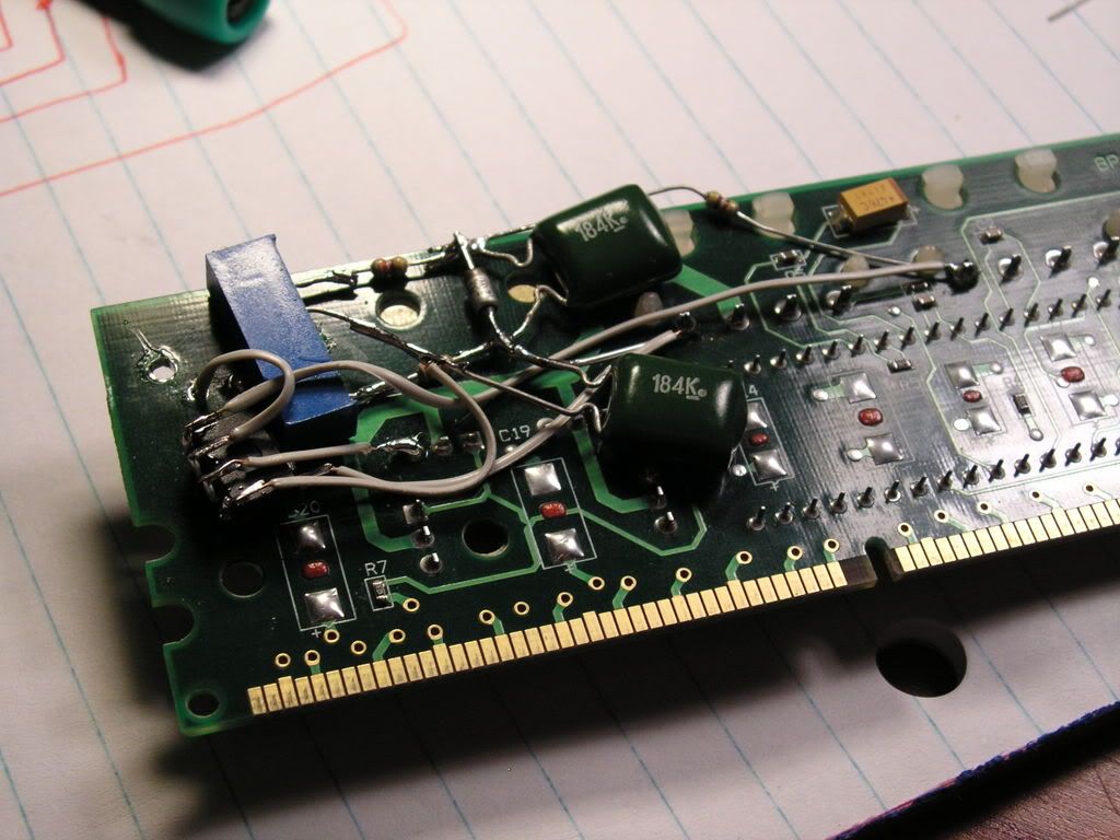
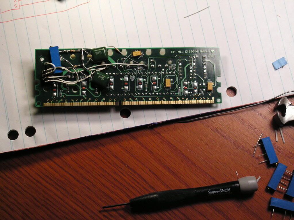
btw here is a pic of the front and back of my booster, let me know if anything looks off
the isolated parts are resistors, one 4.7k and one 15k, it doesnt matter which one is + and which one is gnd right ?
note this is my second revision, I changed the gnd points as the contact on the left was getting overloaded with wires and it was hard to solder, but that shouldnt have changed anything since both are just gnd
Thanks
Dan
Last edited by ZL1; 01-02-2006 at 04:37 AM.
ok got a dmm
pin1 reads 0,80v, pin2 reads 2.42v, pin3 (middle) reads in between 0.8 and 2.42
what do you think ?
Thanks
Dan
Are you sure that the 2 fixed resistors are connected correctly? The 15k should be connected to + and the 4.7k connected to ground.
yep, thats how they are, checked with the dmm a second ago
I do get 4.3 and 12 with the dmm, but thats just because they are on the circuit right ?
Thanks
Dan
Last edited by ZL1; 01-09-2006 at 10:32 AM.
I know this thread is old and hardly anyone still uses DDR Boosters nowadays, but I thought I'd have a go anyway...
I've done the simple mod to my Booster without any fixed resistors (just got to be a little more careful) and it has lowered my overclock on my RAM. With the original Booster I could hit 230MHz on 3.2v, but now I can't get 220MHz stable at any voltage.
My RAM is 2 x 512MB sticks of A-Data PC2700 with BH-6 chips. This is quite a noisy PCB, so I was wondering if the modded Booster might be providing noisier power than an unmodded one? Is that possible?
Also, ZL1, did you ever get yours to work? It's just that you also run a P4C800, so it would be nice to compare notes
The stable voltage is nice, but the lower overclock is puzzling... Any help would be much appreciated!
P4C800 with custom BIOS to allow multiplier adjustment
Dothan 760 @ 2.64GHz
6800LE 12pp 6vs 420/940 daily clock, 1.4v VGPU, 2.82v VMem.
Any updates..?
Venice 3500+ M @ 3ghz - Lanparty nf4 2 dimms dead
Cpu: Prommy chilled

Did this today, havent tested it yet
Q9550 || DFI P45 Jr || 4x 2G generic ram || 4870X2 || Aerocool M40 case || 3TB storage
 Posting Permissions


 Reply With Quote


Bookmarks