Page 1 of 3 123 LastLast
Results 1 to 25 of 64

Thread: Modding a ZIPPY 700Watts PSU....12V - 5V - 3.3V...

  1. #1
    k|ngp|n/Sham my brothers
    Join Date
    Aug 2002
    Location
    Athens---Hellas
    Posts
    5,693

    Modding a ZIPPY 700Watts PSU....12V - 5V - 3.3V...

    Yup.......That's right.......I always mod so I just couldn't handle not to mod this one too.....

    These mods are a bit difficult.......The easiest one is only the 12Volts rail - piece of cake -......

    Let's start from the box of it....

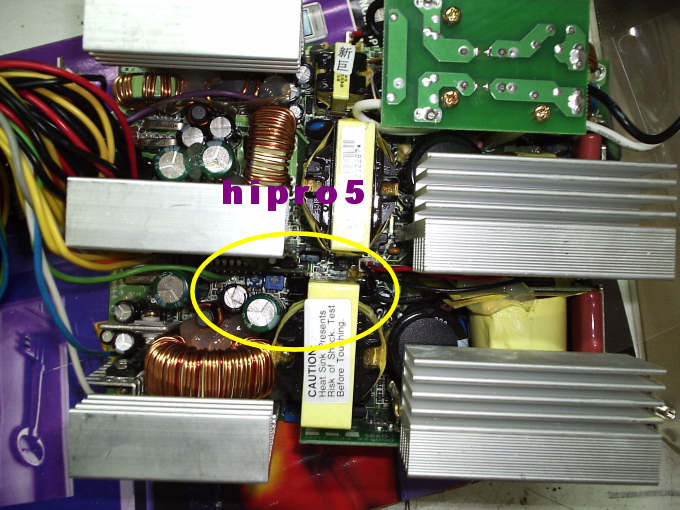
    Here we can see how HUGE it is....


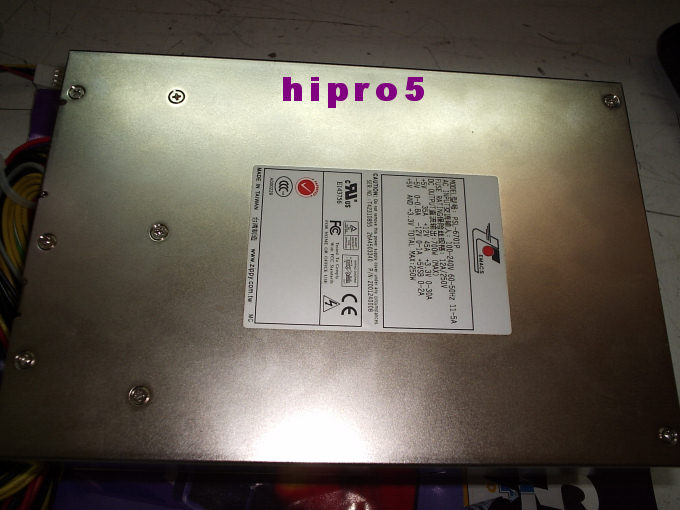
    We open it and we search for this area....


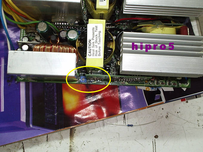
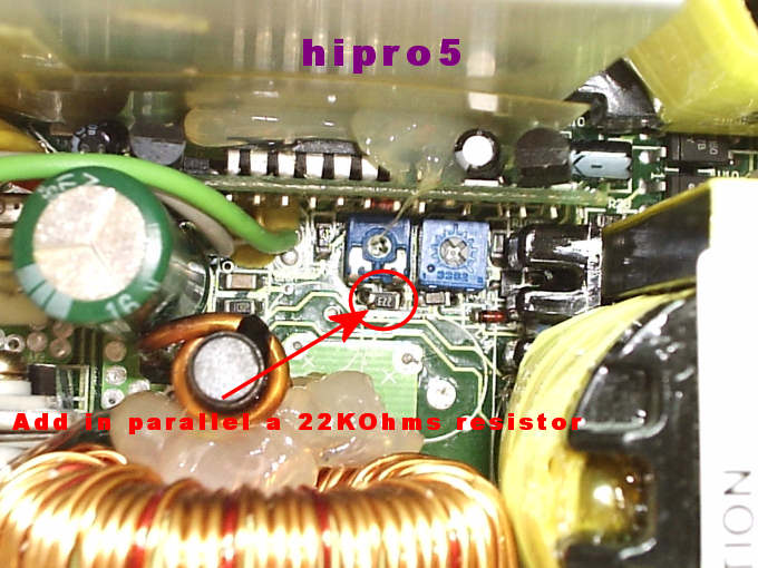
    ........and with a closer look we see a trimmer and one resistor 1/8Watts right to it.....


    Well this trimmer adjusts the +12Volts rail........

    To get more voltage out of it we just solder in parallel with the existing 1/8 Watts resistor a 22KOhms one........


    Before the soldering and by default the +12Volts rail was adjusted from min 11.59Volts to MAX 12.47 Volts.........WITH the 22KOhms resistor it now adjusts from 11.92 Volts to 13.05Volts......

    To "start" the PSU so as to measure the Voltages we simply short circuit the green cable with a black one(as a matter of fact I always use a 330Ohms resistor to do so from green cable to any black one near it)........


    NOW the HARD way.......

    3.3Volts line and 5Volts line......

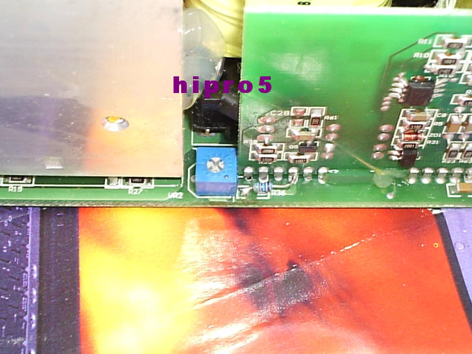
    We track this area.....


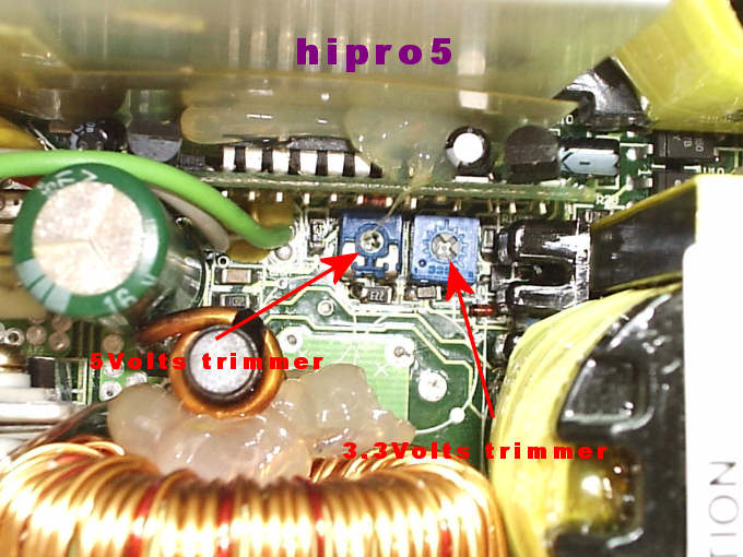
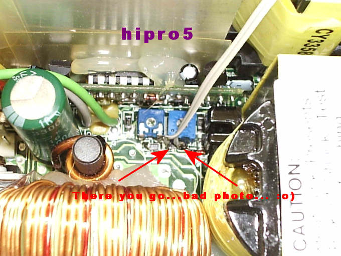
    With a closer look we see two tiny trimmer down there......The left one is for the 5Volts line and the right one is for the 3.3Volts line.....


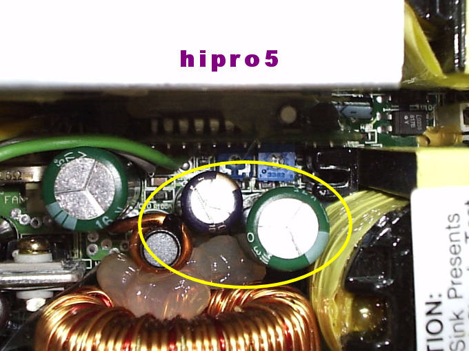
    As you can see I have circled with yellow paint TWO electrolytic capacitors.........U N F O R T U N A T E L Y they HAVE TO BE REMOVED so as to work down there.......

    So let's do it......We unsolder them from the backside of the PSU's PCB......AND......


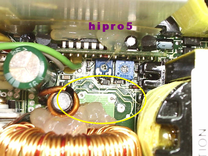
    Now we can work somehow down there.......


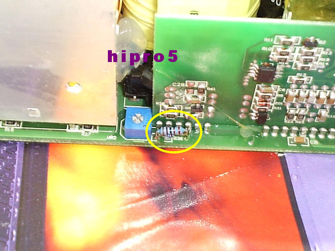
    Now we have to solder an 22KOhms resistor in parallel with the existing SMD one for the 5Volts line like in the below pic........


    Best is to use an SMD 22KOhms resistor so as to be small.......

    Before the soldering we measured on the 5Volts line from 4.82Volts to 5.31Volts by adjusting the left trimmer......

    With the 22KOhms resistor we can now trim it from 4.83Volts up to 5.51Volts.....

    Ready with the 5Volts line.......Continuing with the 3.3Volts line.....

    Take a look at this tiny SMD resistor.....and on the spots I've paint.......


    Here we have to solder two slim cables.......One at the left end of this resistor and one on the right end of it......like the below pic......


    After that we re-solder the two unsoldered electrolytic capacitors..........


    Now we get a driller and we drill a small hole on the backside of our PSU so as to glue a trimmer there like this.....The hole was done with a 3mm drill......


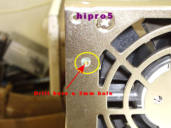
    ........and one from the inside the PSU's box.....


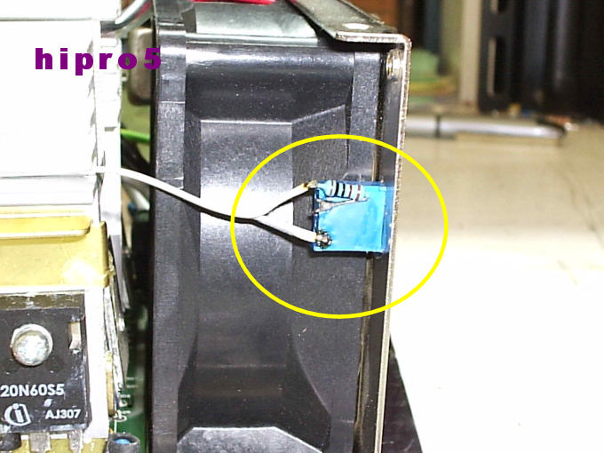
    We solder a 10KOhms trimmer of 25turnsand we ALSO solder a 10KOhms resistor in SERIES with it......So we can have a total 10K trimmer + 10K resistor = 20KOhms......

    Then we solder the two cables from the 3.3Volts line onto the trimmer and resistor like the pic above......

    Another close look of that cable is this........As you can see I have painted with red paint the direction of that cable....


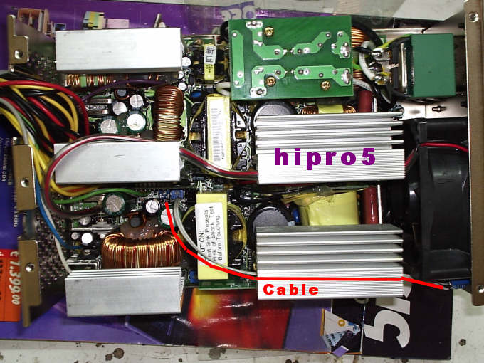
    By default we could trim the 3.3Volts line from 3.26Volts up to 3.57Volts...........Now we can trim it from 3.65Volts to 3.75Volts.......IF we want less than 3.65Volts , then we can put a 50KOhms trimmer instead of the 10 KOhms trimmer.......

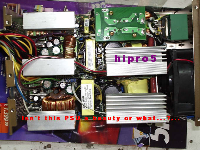
    Now tell me...........ISN'T that a beauty or what........?..........


    Observations :

    Those Voltages where measured with the PSU OUT of the box and with OUR start up........NOT with it's "normal" start up via Motherboard.......Then we put it into our box , pluged it with the Mobo(Motherboard) and we measure the following Voltages : +12Volts = 13.02Volts , +5Volts =
    +5.5Volts , +3.3Volts = +3.65Volts(with the trimmer adjusted at +3.65Volts).......


    With a full load of a Pentium4 3.8GHz @ 5300MHz plus extras (4 x Delta fans 2A each 12 x 12cm 190cfms - e.t.c.) , we measured the following Voltages :

    FULL - FULL LOAD : From 13.02 it drops at 13.01Volts.......From 5.5Volts it drops at 5.49Volts.......From 3.65Volts it drops at 3.64Volts.......

    To tell you the truth I just COULDN'T believe it my self...........

    FIRST TIME in my Overclocking life I show this PERFECT Vdroop......ONLY 0.01Volts on EACH rail........

    ZIPPY did a PERFECT and clean job , WELL sophisticated with HIGH END materials in it ( it EVEN have Rubicon capacitors)

    END : I proudly could say : " hipro5 APPROVED"

    Thanks ZIPPY for this piece of beauty (not outside good-looking for "effe" reasons BUT for it's INSIDE circuit).....
    Last edited by hipro5; 02-17-2005 at 06:10 AM.
    INTEL PWA FOR EVER

    Dr. Who my arss...

    .........


  2. #2
    Sandoval
    Join Date
    Jun 2004
    Location
    ehn why cee
    Posts
    470
    beautiful mods!!! i wish you lived in new york city and i could drop by and have you mod my stuff! i can't wait til your maximizer is ready for use with the zippy!

    i7 980x | corsair dominator 6x4 Gb | TJ07
    SLI GTX 580x2 | GT430 | rampage 3 | corsair AX1200
    LSI 9265 | OCZ vertex 128x4 raid0 | corsair c300 | hitachi 3tbx3 |
    blocks: cpu hk 3.0 | gpu aquacomputer 580x2 | mb ek re3 fc | ram bitspower galaxy
    pump: laing d5 x2 | res: koolance 452x2
    rad: TC 120.3 120.2 | scythe GTx5
    NASs: qnap 879 8x3tb | thecus N5200 2tbx5

  3. #3
    k|ngp|n/Sham my brothers
    Join Date
    Aug 2002
    Location
    Athens---Hellas
    Posts
    5,693
    Quote Originally Posted by jikdoc
    beautiful mods!!! i wish you lived in new york city and i could drop by and have you mod my stuff! i can't wait til your maximizer is ready for use with the zippy!
    Thanks M8.......
    INTEL PWA FOR EVER

    Dr. Who my arss...

    .........


  4. #4
    Xtreme Mentor
    Join Date
    May 2003
    Location
    Engineering Lab - NCSU
    Posts
    2,978
    Nicely done as usual hip.


    I like my women the way I like my processors...naked.
    I am not the HellFire that writes bios files. I work strictly on voltage modifications.

  5. #5
    Xtreme Member
    Join Date
    May 2004
    Location
    Montreal
    Posts
    283
    Simply awesome mod hypro !

    I dont think I'll ever have the skills to do such a hard mod.
    Last edited by Nanobot; 04-11-2005 at 04:08 AM.
    Asus P6T Deluxe, Core i7 920 @ 4.1ghz, Corsair Dominator Tri channel 1600Mhz
    Evga GTX285, Raptor 150GB, Corsair HX620

    Apogee GTZ, PA 120.3, CM Stacker STC-01, DDC 3.1 MCP355/XSPC top.
    Win Vista Premium X64

  6. #6
    IT Engineer in the making
    Join Date
    Jun 2003
    Location
    Former Kingdom of Bavaria
    Posts
    2,094
    Very good work, as always! You got my respect for sure.

    Just one quick question:

    Why unsolder the capacitors from the pcb. Wouldn't it be possible to just solder in the smd resistor on the back of the pcb and leave the caps in place?
    I mean, you've got to dissemble the whole PSU anyway, so this would be a easier way IMHO.
    Quote from one of our professors:
    "Reality is hiding in the imaginary part."

  7. #7
    k|ngp|n/Sham my brothers
    Join Date
    Aug 2002
    Location
    Athens---Hellas
    Posts
    5,693
    Thank you guys......
    INTEL PWA FOR EVER

    Dr. Who my arss...

    .........


  8. #8
    k|ngp|n/Sham my brothers
    Join Date
    Aug 2002
    Location
    Athens---Hellas
    Posts
    5,693
    Quote Originally Posted by celemine1Gig
    Why unsolder the capacitors from the pcb. Wouldn't it be possible to just solder in the smd resistor on the back of the pcb and leave the caps in place?
    I mean, you've got to dissemble the whole PSU anyway, so this would be a easier way IMHO.
    Unfortunately with the SMD parts there are lines between them and the trimmers ONLY at the top of the PCB.........At the back of it there are other circuits......
    INTEL PWA FOR EVER

    Dr. Who my arss...

    .........


  9. #9
    XS Local
    Join Date
    Dec 2001
    Location
    Close to Neweggs New RMA Center, CA
    Posts
    2,246
    told ya these psus are the best

    well jinu117 kinda told me but yea, i was the second to have one to say the least ;


    Opteron 175 Dual Core CCBWE 0544XPMW @2.3ghz 1.41v
    DFI SLI-DR Expert 11-25 Bios
    G-Skill 1gb GH UTT @210 2-2-2-5
    BFG 7800GT OC 485/1170 NV 5rev3
    74gb Raptor 300gb Maxtor 500gb Hitachi
    OCZ 520w SLI 3.46v 5.16v 12.64v
    Thermaltake CL-P0114 Big Typhoon
    3dmark01 3dmark05
    Heatware

  10. #10
    k|ngp|n/Sham my brothers
    Join Date
    Aug 2002
    Location
    Athens---Hellas
    Posts
    5,693
    Agree.......EVEN "as is" ROCKS big time.....
    INTEL PWA FOR EVER

    Dr. Who my arss...

    .........


  11. #11
    IT Engineer in the making
    Join Date
    Jun 2003
    Location
    Former Kingdom of Bavaria
    Posts
    2,094
    Quote Originally Posted by hipro5
    Unfortunately with the SMD parts there are lines between them and the trimmers ONLY at the top of the PCB.........At the back of it there are other circuits......
    Ah, OK, just realized that the mod involves soldering to an existing smd resistor on the pcb and not directly to the existing pots. Sorry, just got it confused. Now that's clear that the smd parts do not connect to the backside of the pcb.
    Quote from one of our professors:
    "Reality is hiding in the imaginary part."

  12. #12
    Xtreme Addict
    Join Date
    Jan 2004
    Location
    Saskatoon, SK
    Posts
    1,149
    Wow, amazing work as always bro.....I didn't think there was much that could be done to make these works of arts any better.....but you've proved me wrong.
    • Intel Core i7 875K @ 3.86GHz 1.35v /w Intel Extreme Tower Heatsink
    • Intel Extreme DP55KG
    • 2x2GB Kingston HyperX PC3-10666
    • ATI HD5970 2GB @ 850/1,200
    • Lian-Li PC-7B
    • Corsair TX750 PSU

  13. #13
    Xtreme Member
    Join Date
    Mar 2004
    Location
    New York
    Posts
    343
    Nice work.. man that thing is a monster !!

  14. #14
    Xtreme Addict
    Join Date
    Jan 2004
    Location
    Saskatoon, SK
    Posts
    1,149
    Quote Originally Posted by THunDA
    Nice work.. man that thing is a monster !!
    Sounds like one too.
    • Intel Core i7 875K @ 3.86GHz 1.35v /w Intel Extreme Tower Heatsink
    • Intel Extreme DP55KG
    • 2x2GB Kingston HyperX PC3-10666
    • ATI HD5970 2GB @ 850/1,200
    • Lian-Li PC-7B
    • Corsair TX750 PSU

  15. #15
    k|ngp|n/Sham my brothers
    Join Date
    Aug 2002
    Location
    Athens---Hellas
    Posts
    5,693
    Quote Originally Posted by Cornelious0_0
    Sounds like one too.


    Yes it does........For a moment I was about to change it's fan and replace it with an DELTA 8 x 8cm 80cfm but the default one is doing a grate job after all.......
    INTEL PWA FOR EVER

    Dr. Who my arss...

    .........


  16. #16
    Xtreme Addict
    Join Date
    Jan 2004
    Location
    Saskatoon, SK
    Posts
    1,149
    Quote Originally Posted by hipro5


    Yes it does........For a moment I was about to change it's fan and replace it with an DELTA 8 x 8cm 80cfm but the default one is doing a grate job after all.......
    Yeah, I'd like to look at throwing one in my rig....but once I get my case mods done and pickup a VapoLS to get a few mods done too....my goal is to have the nicest/sexiest single stage PS setup ppl have seen. All too often phase change rigs are all about power and look like a$$....I'm gonna try and change that, and show people that you CAN mix beauty and power.....

    /offtopic
    • Intel Core i7 875K @ 3.86GHz 1.35v /w Intel Extreme Tower Heatsink
    • Intel Extreme DP55KG
    • 2x2GB Kingston HyperX PC3-10666
    • ATI HD5970 2GB @ 850/1,200
    • Lian-Li PC-7B
    • Corsair TX750 PSU

  17. #17
    THE ORIGINAL OC JEDI
    Join Date
    Oct 2002
    Location
    Field of Battle
    Posts
    8,973
    great work, HiPro!!!
    But what's the deal about ZIppy700w NOT working on DFI NF4???????
    why not?

  18. #18
    k|ngp|n/Sham my brothers
    Join Date
    Aug 2002
    Location
    Athens---Hellas
    Posts
    5,693
    Quote Originally Posted by charlie
    great work, HiPro!!!
    But what's the deal about ZIppy700w NOT working on DFI NF4???????
    why not?
    Someone will bring me a DFI NF4 one of these days and I'll know for sure.....
    INTEL PWA FOR EVER

    Dr. Who my arss...

    .........


  19. #19
    Xtreme Addict
    Join Date
    Jan 2004
    Location
    Saskatoon, SK
    Posts
    1,149
    Quote Originally Posted by hipro5
    Someone will bring me a DFI NF4 one of these days and I'll know for sure.....
    I don't understand the incompatibility much myself...but if anyone, you'll be the guy to find a way around it I'm sure.
    • Intel Core i7 875K @ 3.86GHz 1.35v /w Intel Extreme Tower Heatsink
    • Intel Extreme DP55KG
    • 2x2GB Kingston HyperX PC3-10666
    • ATI HD5970 2GB @ 850/1,200
    • Lian-Li PC-7B
    • Corsair TX750 PSU

  20. #20
    Sandoval
    Join Date
    Jun 2004
    Location
    ehn why cee
    Posts
    470
    i don't have the skills to do your mod hipro, but i want to increase the volts on my 3.3 line. what safety precautions do i need to take before i stick a screwdriver downthere to turn the pot. also, increasing is clockwise, and how much should i turn it to get 0.2v? right now at stock, it's running @ 3.38 with dmm. i'd like 3.5 for my twinmos utt to really fly.
    Last edited by jikdoc; 02-17-2005 at 09:02 PM.

    i7 980x | corsair dominator 6x4 Gb | TJ07
    SLI GTX 580x2 | GT430 | rampage 3 | corsair AX1200
    LSI 9265 | OCZ vertex 128x4 raid0 | corsair c300 | hitachi 3tbx3 |
    blocks: cpu hk 3.0 | gpu aquacomputer 580x2 | mb ek re3 fc | ram bitspower galaxy
    pump: laing d5 x2 | res: koolance 452x2
    rad: TC 120.3 120.2 | scythe GTx5
    NASs: qnap 879 8x3tb | thecus N5200 2tbx5

  21. #21
    k|ngp|n/Sham my brothers
    Join Date
    Aug 2002
    Location
    Athens---Hellas
    Posts
    5,693
    Quote Originally Posted by jikdoc
    i don't have the skills to do your mod hipro, but i want to increase the volts on my 3.3 line. what safety precautions do i need to take before i stick a screwdriver downthere to turn the pot. also, how increasing is clockwise, and how much should i turn it to get 0.2v? right now at stock, it's running @ 3.38 with dmm. i'd like 3.5 for my twinmos utt to really fly.
    The 3.3Volts line increases it's voltage clockwise.......The 5Volts opposite......Precautions is only if you can bend your tiny screw driver with some tape not to short circuit something in there in case you tremble.......
    INTEL PWA FOR EVER

    Dr. Who my arss...

    .........


  22. #22
    Xtreme Addict
    Join Date
    Nov 2004
    Posts
    1,363
    Quote Originally Posted by hipro5
    The 3.3Volts line increases it's voltage clockwise.......The 5Volts opposite......Precautions is only if you can bend your tiny screw driver with some tape not to short circuit something in there in case you tremble.......
    Hell id be more worried about electrocuting myself with that being 700W and all :O

    I really dont understand why they cant align all the pots the same. Friend of mine workin on his fortron didnt realize this and damn near blew out his PC. Good thing he had a DMM handy
    NZXT Tempest | Corsair 1000W
    Creative X-FI Titanium Fatal1ty Pro
    Intel i7 2500K Corsair H100
    PNY GTX 470 SLi (700 / 1400 / 1731 / 950mv)
    Asus P8Z68-V Pro
    Kingston HyperX PC3-10700 (4x4096MB)(9-9-9-28 @ 1600mhz @ 1.5v)

    Heatware: 13-0-0

  23. #23
    XS Local
    Join Date
    Dec 2001
    Location
    Close to Neweggs New RMA Center, CA
    Posts
    2,246
    Quote Originally Posted by Sentential
    Hell id be more worried about electrocuting myself with that being 700W and all :O

    I really dont understand why they cant align all the pots the same. Friend of mine workin on his fortron didnt realize this and damn near blew out his PC. Good thing he had a DMM handy
    i doubt they think about making the pots together so we can open up the psu to tweak them. AFAIK you open the zippy and bbai warranty


    Opteron 175 Dual Core CCBWE 0544XPMW @2.3ghz 1.41v
    DFI SLI-DR Expert 11-25 Bios
    G-Skill 1gb GH UTT @210 2-2-2-5
    BFG 7800GT OC 485/1170 NV 5rev3
    74gb Raptor 300gb Maxtor 500gb Hitachi
    OCZ 520w SLI 3.46v 5.16v 12.64v
    Thermaltake CL-P0114 Big Typhoon
    3dmark01 3dmark05
    Heatware

  24. #24
    Xtreme Mentor
    Join Date
    Oct 2004
    Posts
    2,544
    Quote Originally Posted by charlie
    great work, HiPro!!!
    But what's the deal about ZIppy700w NOT working on DFI NF4???????
    why not?
    It works with the DFI board, but not with the 4.0VDIMM option enabled.

  25. #25
    THE ORIGINAL OC JEDI
    Join Date
    Oct 2002
    Location
    Field of Battle
    Posts
    8,973
    Quote Originally Posted by conrad.maranan
    It works with the DFI board, but not with the 4.0VDIMM option enabled.
    why not?

Page 1 of 3 123 LastLast

Bookmarks

Bookmarks

Posting Permissions

  • You may not post new threads
  • You may not post replies
  • You may not post attachments
  • You may not edit your posts
  •