Yup.......That's right.......I always mod so I just couldn't handle not to mod this one too.....
These mods are a bit difficult.......The easiest one is only the 12Volts rail - piece of cake -......
Let's start from the box of it....
Here we can see how HUGE it is....
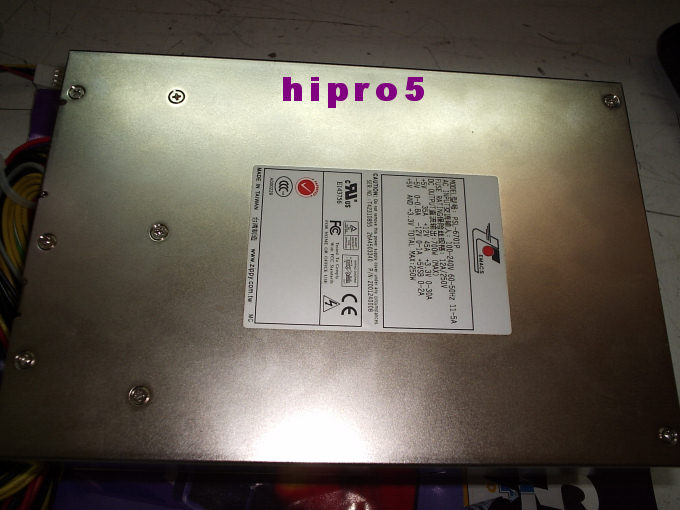
We open it and we search for this area....
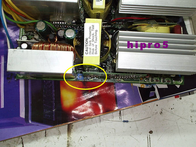
........and with a closer look we see a trimmer and one resistor 1/8Watts right to it.....
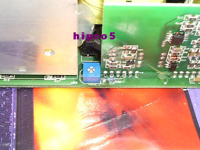
Well this trimmer adjusts the +12Volts rail........
To get more voltage out of it we just solder in parallel with the existing 1/8 Watts resistor a 22KOhms one........
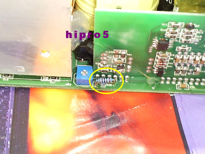
Before the soldering and by default the +12Volts rail was adjusted from min 11.59Volts to MAX 12.47 Volts.........WITH the 22KOhms resistor it now adjusts from 11.92 Volts to 13.05Volts......
To "start" the PSU so as to measure the Voltages we simply short circuit the green cable with a black one(as a matter of fact I always use a 330Ohms resistor to do so from green cable to any black one near it)........
NOW the HARD way.......
3.3Volts line and 5Volts line......
We track this area.....
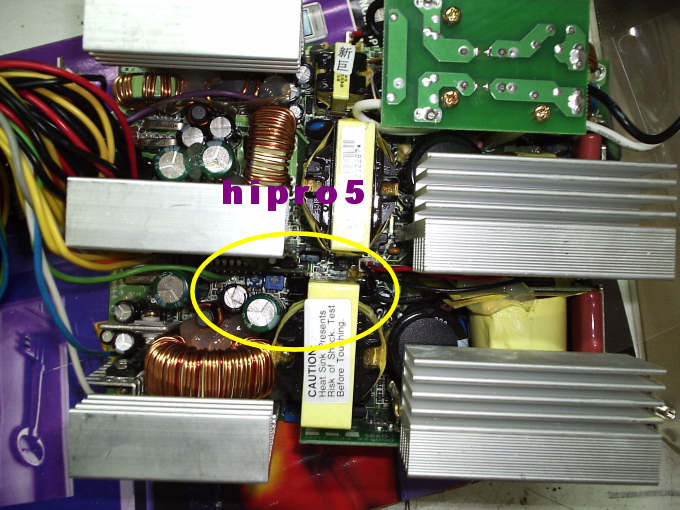
With a closer look we see two tiny trimmer down there......The left one is for the 5Volts line and the right one is for the 3.3Volts line.....
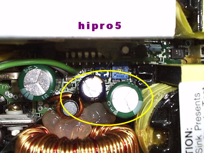
As you can see I have circled with yellow paint TWO electrolytic capacitors.........U N F O R T U N A T E L Y they HAVE TO BE REMOVED so as to work down there.......
So let's do it......We unsolder them from the backside of the PSU's PCB......AND......
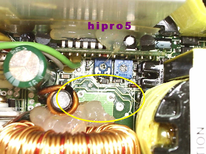
Now we can work somehow down there.......
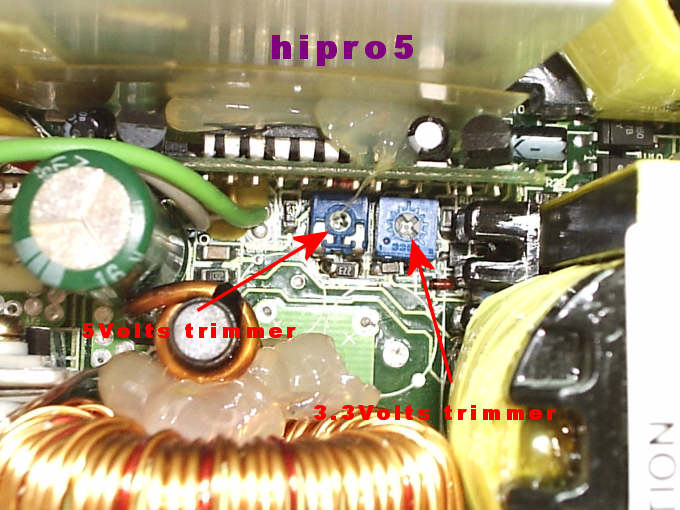
Now we have to solder an 22KOhms resistor in parallel with the existing SMD one for the 5Volts line like in the below pic........
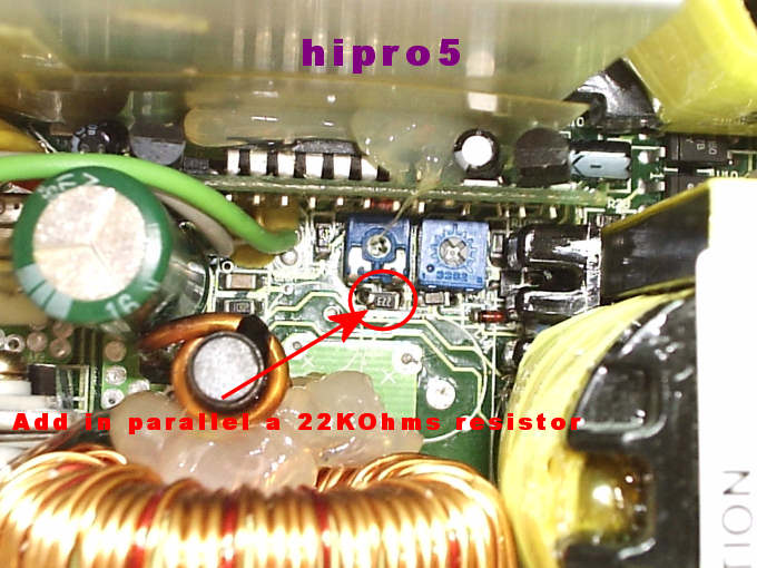
Best is to use an SMD 22KOhms resistor so as to be small.......
Before the soldering we measured on the 5Volts line from 4.82Volts to 5.31Volts by adjusting the left trimmer......
With the 22KOhms resistor we can now trim it from 4.83Volts up to 5.51Volts.....
Ready with the 5Volts line.......Continuing with the 3.3Volts line.....
Take a look at this tiny SMD resistor.....and on the spots I've paint.......
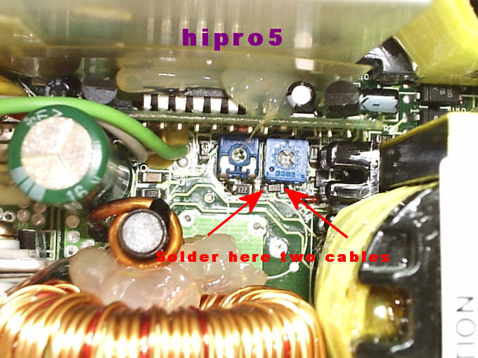
Here we have to solder two slim cables.......One at the left end of this resistor and one on the right end of it......like the below pic......
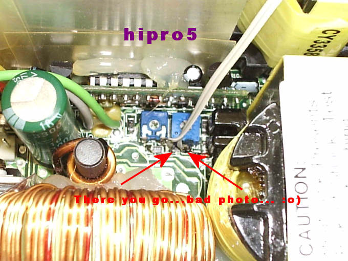
After that we re-solder the two unsoldered electrolytic capacitors..........

Now we get a driller and we drill a small hole on the backside of our PSU so as to glue a trimmer there like this.....The hole was done with a 3mm drill......
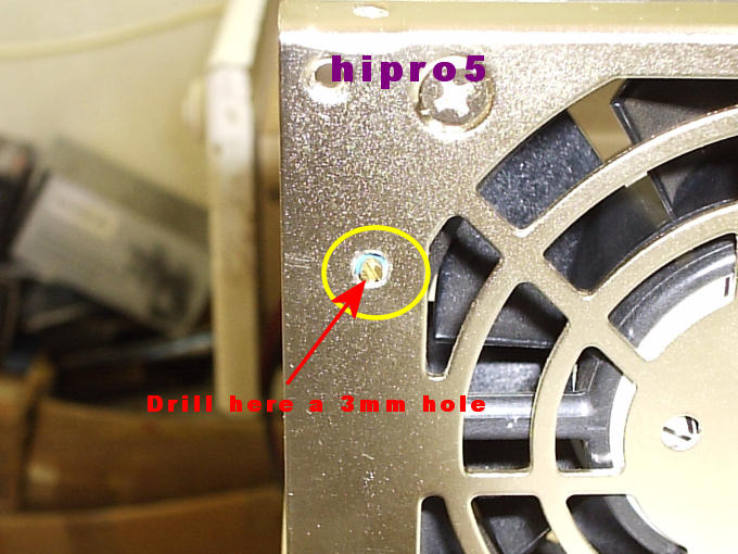
........and one from the inside the PSU's box.....
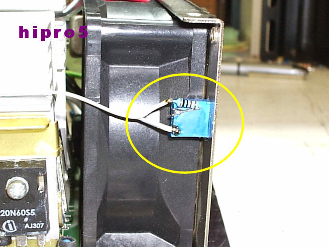
We solder a 10KOhms trimmer of 25turnsand we ALSO solder a 10KOhms resistor in SERIES with it......So we can have a total 10K trimmer + 10K resistor = 20KOhms......
Then we solder the two cables from the 3.3Volts line onto the trimmer and resistor like the pic above......
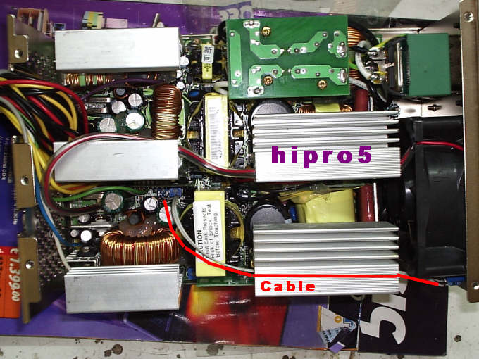
Another close look of that cable is this........As you can see I have painted with red paint the direction of that cable....
By default we could trim the 3.3Volts line from 3.26Volts up to 3.57Volts...........Now we can trim it from 3.65Volts to 3.75Volts.......IF we want less than 3.65Volts , then we can put a 50KOhms trimmer instead of the 10 KOhms trimmer.......
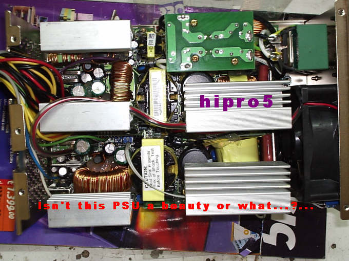
Now tell me...........ISN'T that a beauty or what........?..........
Observations :
Those Voltages where measured with the PSU OUT of the box and with OUR start up........NOT with it's "normal" start up via Motherboard.......Then we put it into our box , pluged it with the Mobo(Motherboard) and we measure the following Voltages : +12Volts = 13.02Volts , +5Volts =
+5.5Volts , +3.3Volts = +3.65Volts(with the trimmer adjusted at +3.65Volts).......
With a full load of a Pentium4 3.8GHz @ 5300MHz plus extras (4 x Delta fans 2A each 12 x 12cm 190cfms - e.t.c.) , we measured the following Voltages :
FULL - FULL LOAD : From 13.02 it drops at 13.01Volts.......From 5.5Volts it drops at 5.49Volts.......From 3.65Volts it drops at 3.64Volts.......
To tell you the truth I just COULDN'T believe it my self...........
FIRST TIME in my Overclocking life I show this PERFECT Vdroop......ONLY 0.01Volts on EACH rail........
ZIPPY did a PERFECT and clean job , WELL sophisticated with HIGH END materials in it ( it EVEN have Rubicon capacitors)
END : I proudly could say : " hipro5 APPROVED"

Thanks ZIPPY for this piece of beauty (not outside good-looking for "effe" reasons BUT for it's INSIDE circuit).....


 Reply With Quote

Bookmarks