Page 1 of 3 123 LastLast
Results 1 to 25 of 72

Thread: Mad scientist lab: NF7-S 4 phase CPU power supply mod

  1. #1
    Xtreme Member
    Join Date
    Aug 2003
    Location
    Slovenia
    Posts
    121

    Mad scientist lab: NF7-S 4 phase CPU power supply mod

    Hello!

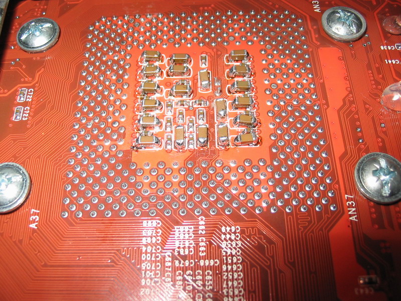
    Quite some time ago, while I was reading datasheet of HIP6301 CPU PWM voltage controler, I found out that it is possible to add fourth phase on the NF7 motherboard... Of course I wanted to to it! But there was a problem, I needen exactly same components as they are in other three phases on board, so I started searching for a dead NF7 board. And then I finaly got one after three months.

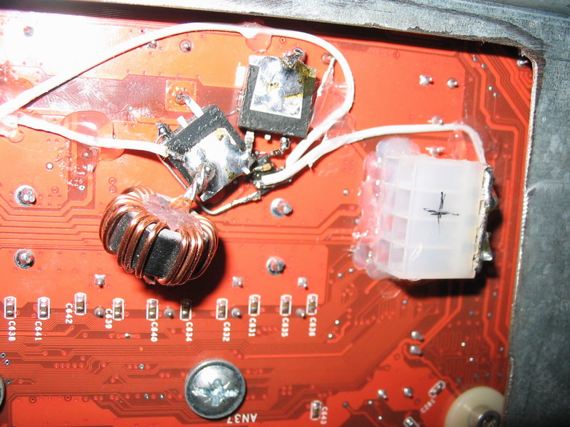
    This board was source of components. I needed 2 MOSFETs, choke, HIP6601 chip and a few condensators and resistors.

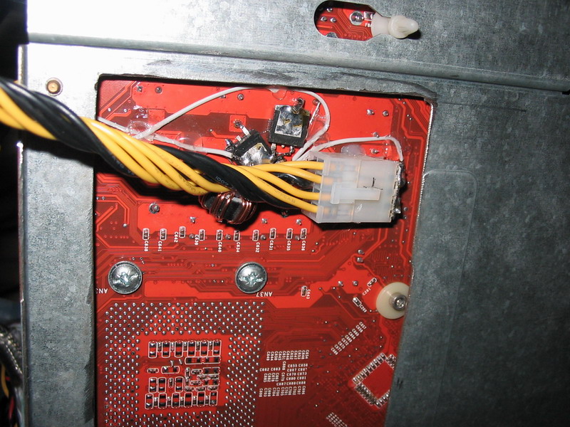
    Then I started "engineering". It took me almost 5 hours to make this mod. And now it is working. I havent tried it in my main rig with Barton, but it is running like a charm with Duron 750 in my test rig...

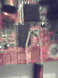
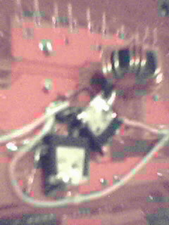
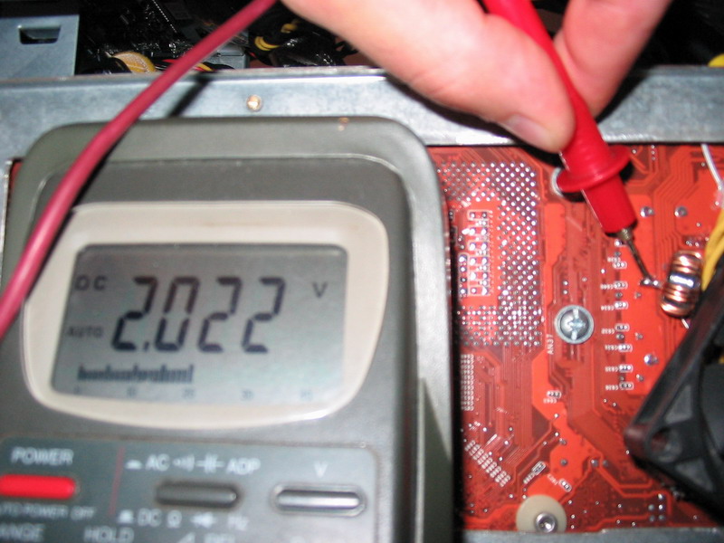
    Unfortunately I don't have a digital camera, but I made few pictures with camera integrated in my cell phone. Quality is very bad... but it is better than nothing... I will borrow a camera from a friend of mine and make some better pictures... until then this is the best I can show you.


  2. #2
    Xtreme Mentor
    Join Date
    Nov 2003
    Posts
    2,672
    Interesting, look forward to seeing some results.

  3. #3
    Xtreme Mentor
    Join Date
    May 2003
    Location
    Engineering Lab - NCSU
    Posts
    2,978
    Where did you add the 2nd HIP IC?


    I like my women the way I like my processors...naked.
    I am not the HellFire that writes bios files. I work strictly on voltage modifications.

  4. #4
    Xtreme Member
    Join Date
    Aug 2003
    Location
    Slovenia
    Posts
    121
    Interesting, look forward to seeing some results.
    Me to... I went directly to bed yesterday after posting this, because it was 1AM and I was very tired... now I will call my friend to borrow the camera... and make some good pictures. Then I will mount this baby in my main rig... and we will se how it works

    Where did you add the 2nd HIP IC?
    It is located between those two MOSFETs, you probably cant see it becase all the mess around it. It is placed where those two grey wires go...

  5. #5
    Xtreme Member
    Join Date
    Aug 2003
    Location
    Slovenia
    Posts
    121
    Huh... I was unable to get camera... so I began testing...

    So far things are running fine. CPU overclock is 40MHz higher than before. Before I was running my Barton at 2512MHz voltage was 2.125V set in BIOS, but it fluctuated 80mV measured with MBM.
    Now i am able to run CPU at 2550MHz with 2.075V set in BIOS and voltage fluctuates only 50mV, wich is far better than before.

    But there is one problem, those two MOSFETs I added are hot like hell. Probably because they are not soldered to the board like the other ones. I'll have to think about that... at the moment I am cooling it with additional fan blowing at it... but I will have to cool it with heatsinks...

    Now I am planing to do some further modifications. First one will be adding capacitors on free spaces on back side of CPU socket, I will take them from dead board and solder them on my working one. I am also thinking of raising the switching frequency of PWM CPU power suppy... Now it is switching with 180kHz, but on the other NF7 I own the frequency is 193kHz, and that board has lower voltage fluctuation, so rising frequency may help a litle bit.

  6. #6
    Banned
    Join Date
    Jun 2003
    Location
    Broomfield, CO
    Posts
    3,882
    Be careful as raising switching frequency will also play a HUGE role in the losses of the upper MOSFET...i.e. it will get a lot hotter.

  7. #7
    Xtreme Member
    Join Date
    Aug 2003
    Location
    Slovenia
    Posts
    121
    Hello!

    Finaly I am able to show you better pictures.


    Now you can see details, but the problem is because everything is so small and messy. I had to improvise. Those two wires that go on the front side of the board are PWM signal and Isen sense line for fourth phase. Chip wich controls MOSFETs is located between MOSFETs, where all the wires go. Also there are a few small SMD capacitors and resistors soldered directly between legs of that chip... as I said before It is a mess. But it is working. So far...

    As you can probably see from the pictures above I've soldered aditional 8 pin ATX_12V connector to my board, so I can use both ATX_12V supply lines on my Tagan PSU. It decreases voltage drop across cables for 20mV...

    Thats it.

    Be careful as raising switching frequency will also play a HUGE role in the losses of the upper MOSFET...i.e. it will get a lot hotter.
    Thanks for warning me, but I am aware of that problem, I am studying elecronics engineering and I know quite a lot about PWM voltage regulators.

  8. #8
    Xtreme Member
    Join Date
    Nov 2003
    Posts
    159
    this is cool, messy but cool. Have u tried to push the vcore to see how it acts on high levels? (about 2-2.2v)?

  9. #9
    Xtreme Member
    Join Date
    Aug 2003
    Location
    Slovenia
    Posts
    121
    The highes voltage I can achive is 2.25V And it works without problems... before the overcurrent protection kicked in at about 2.15V

    Here I took a picture to prove that this thing is working. CPU is Barton 2600+ at 2553MHz Voltage in BIOS is set to 2.05V

    Idle:


    Full load:


    Quite good

  10. #10
    XS Intel News & DČOL enhanced
    Join Date
    Nov 2003
    Location
    Netherlands
    Posts
    2,205
    very nice.... very xtreme

  11. #11
    Banned
    Join Date
    Jun 2003
    Location
    Broomfield, CO
    Posts
    3,882
    I know quite a lot about PWM voltage regulators
    Hmmm....well, you forgot the extra needed capacitors...should have two electrolytics (6.3V, at least 2200uF...I would probably use 3300uF caps) from the output of the coil to ground (CPU VCC plane -> ground) or else the extra inductance does nothing really as it can't supply any extra load on the negative half-cycles. You can solder those in parallel to the other caps using the through-hole leads on the back of the MB...

    Other than that....(and this is sort of what I am designing as a Vcore booster except the whole regulation system with 4-phases and adjustable droop with be on a single add-on board):

    Creativity: A+ :thumbsup:
    Presentation: D-
    Critical Flaws: F (caps)

  12. #12
    Xtreme Member
    Join Date
    Jun 2004
    Location
    Oregon
    Posts
    416
    arent we critical looks good bro. u should fab it on a board and use wire leads so it looks nicer

    -CaT
    Send Me Your Broken Hardware! - Repair Parts and vMod Research!
    Need vMods? PM Me!

  13. #13
    Xtreme Member
    Join Date
    Oct 2003
    Location
    Albuquerque,NM
    Posts
    234
    is there anyway you can provide spicific info for the parts used. as i can maufacture a few of these if needed if i have the part numbers.
    DFI NF4 Ultra D/3800 x2 @ 2.5ghz/2x512 BH-5/ EVGA 7800 GT /OCZ 600W PowerStream

  14. #14
    Xtreme Member
    Join Date
    Aug 2003
    Location
    Slovenia
    Posts
    121
    Hello everybody!

    Hmmm....well, you forgot the extra needed capacitors...should have two electrolytics (6.3V, at least 2200uF...I would probably use 3300uF caps) from the output of the coil to ground (CPU VCC plane -> ground) or else the extra inductance does nothing really as it can't supply any extra load on the negative half-cycles. You can solder those in parallel to the other caps using the through-hole leads on the back of the MB...
    I didn't forgot the capacitors, but in the first step I just wanted to make sure if everything is working fine. As I said before I have plans to add capacitors to back side of the socket (because you need big energy reserves as close to CPU as possible) and I am also going to add 5 3300uF 6.3V capacitors wich I collected from dead NF7. But this will be done after I am 100% sure everthing is working fine.

    Presentation: D-
    I admit that, but I have another NF7 to mod after I will finish this one. And then I am going to write an step-by-step guide with detailed pictures. But please be patient, I have 2 exams in next 14 days and I don't have a lot of time right now

    u should fab it on a board and use wire leads so it looks nicer
    That's not so good idea. It would sure look nicer, but design on a additional PCB would add a lot of unwanted series resistance wich is not good, especially if current is so high. The current on one phase can be as high as 20A.

    is there anyway you can provide spicific info for the parts used. as i can maufacture a few of these if needed if i have the part numbers.
    As I said in my first post I got all components from a dead NF7 board. Because all the components in fourth phase must be the same type and value as those in other 3 phases. Otherwise the phase load wont be symmetrical.
    The biggest problem is choke, because the value of it is not known. Other components are:

    55N03 upper MOSFET
    50N03 lower MOSFET
    HIP6601 MOSFET driver chip
    4.7, 2.9 and 2900 [ohm] SMD resistors
    10nF and 100nF SMD multilayer capacitors
    choke

    That is all.

  15. #15
    Xtreme Addict
    Join Date
    May 2004
    Location
    Perth, Western Australia
    Posts
    1,622
    that looks good. #1 what is that ps line?
    #2 you need a 2400xpm!
    Quote Originally Posted by bh2k
    sorry m, OI'm a bit drunkz!
    Air benches with 3000+, DFI nf3 and 6800GT 2001SE: 26312 3d03: 13028

  16. #16
    Xtreme Member
    Join Date
    Aug 2003
    Location
    Slovenia
    Posts
    121
    #1 what is that ps line?
    This is additional ATX_12V line. This is special 8pin connector wich is used by server motherboards... My Tagan 480W PSU has this connector, and also a standard 4 pin ATX_12V conn. But I like to use them both at the same time So I soldered another connector in backside of my mobo...

    #2 you need a 2400xpm!
    Sorry but I don't know what this means...

  17. #17
    Xtreme Addict
    Join Date
    May 2004
    Location
    Perth, Western Australia
    Posts
    1,622
    a moblie 2400+ youd get 2.9 i think
    Quote Originally Posted by bh2k
    sorry m, OI'm a bit drunkz!
    Air benches with 3000+, DFI nf3 and 6800GT 2001SE: 26312 3d03: 13028

  18. #18
    Xtreme Member
    Join Date
    Aug 2003
    Location
    Slovenia
    Posts
    121
    Yes it would be nice to have a mobile... but I doubt about those 2900MHz very much. 2700 OK, 2900 not without phasechange.

  19. #19
    Registered User
    Join Date
    Sep 2004
    Location
    Brisbane, Australia
    Posts
    32
    POST #1

    Very nice work TribesMan. I also noticed with my own setup (I used to use a modded NF7-SREV2.0 + 2600+ xp-m. The max i could get was arround the 2800mark 2810 with 200fsb or 2790 with 223fsb. But then after adding some heatsinks to my mosfets i could increase that to 2838mhz with 218fsb. And that was using a cyclone5 and an eheim 1048, anyone remember those :S

    Im sure you could get 2900 with your setup if you found a decent cpu! :P

    that overclock was stable for 13hours 10minutes and 21seconds and can be found in this thread http://forums.overclockers.com.au/sh...08#post3550308
    A64 10*220 1:1 | Gigabyte K8NS. vdimm = 3.40v | 2x512mb BH-5 2-2-2-6-2T G.skill dc kit in sc| 256mb x800xt pe @610/580 | 2 x WD360GB RAID0 |
    SBLIVE DE5.1 + Phililps HP890 | LITEON 52.24.54 CDRW | LG900b 19" CRT |

  20. #20
    Xtreme Member
    Join Date
    Aug 2003
    Location
    Slovenia
    Posts
    121
    New pictures!

    More capacitors added...

    2*3300uF 6.3V, 2200uF 16V, 20* 5uF 6.3V:


    Closeup: underside of the socket and added capacitors:


    The biggest difference between highest and lowest voltage is 30mV... at 2560MHz and 2.1V

  21. #21
    Xtreme Member
    Join Date
    Jun 2004
    Location
    Oregon
    Posts
    416
    Damn nice work bro, what i meant about fabbing it on a PCB, you could use wire leads because 20A would go fine thru 18AWG Wire and if the connections on the board wernt beefy enough you could use wire or solder to reinforce them. THis way you could mount everything but the caps on the topside of the board and have a nice sexy mod. And maybe you could even sell the Pre Fabbed PCB

    -CaT
    Send Me Your Broken Hardware! - Repair Parts and vMod Research!
    Need vMods? PM Me!

  22. #22
    Xtreme Member
    Join Date
    Jul 2004
    Location
    Maryland
    Posts
    246
    Any idea if this works on the AN7?
    Processor: Athlon XP-M 2600 IQYHA 0401
    Motherboard: DFI NF2 Ultra Infinity vcore, vdroop, OCP, vdimm, vdd mods
    Cooling: Swiftech MCW6002a-Swiftech MCP350-Weapon Modded 2-302 headercore+Shroud
    Memory: 2x512 Kingston HyperX KHX3200 BH-5 2-2-2-11
    Power Supply: OCZ Powerstream 520
    Sound Card: EMU 1212m
    Headphone Amp: DIY Pimeta/Mint/CMoy
    Headphones: Senn HD580/Etymotic ER6i/Sony MDR-D66 Eggos/Koss ksc75/Shure E2c
    Video Card: Radeon 9600 Pro @ 489 Core/680 Mem fdd power mod, vmem, vgpu

  23. #23
    Xtreme X.I.P.
    Join Date
    Nov 2002
    Location
    Shipai
    Posts
    31,147
    very sweet! i think i remember you, didnt you build an agp pci lock on an old board and oced a celeron to sick speeds?

    great work! nice to see the mad scientists lab in full action again! XD

  24. #24
    Xtreme Member
    Join Date
    Jul 2004
    Location
    Lucerne, Switzerland
    Posts
    178
    wow, thats very nice
    very xtreme
    can you make a shematic diagramm?
    Last edited by blander; 09-16-2004 at 12:15 PM.
    Single 7800GT 3dMark2001 54939 3dMark03 22547 3dMark05 9968 3dMark06 5590 Aquamark 150656

  25. #25
    Xtreme Member
    Join Date
    Aug 2003
    Location
    Slovenia
    Posts
    121
    Hello! Me again... Lets answer some questions...

    Any idea if this works on the AN7?
    It should... I think that AN7 uses sam voltage controler as NF7, so it I think this mod is possible. I also know it is possible to do it on DFI Infinity NFII, because it uses HIP6301 like NF7...

    very sweet! i think i remember you, didnt you build an agp pci lock on an old board and oced a celeron to sick speeds?
    Guilty... click1 click2 click3

    can you make a shematic diagramm?
    I will... I promise, but first I have to pass 2 exams... so give me 1 week...

Page 1 of 3 123 LastLast

Bookmarks

Bookmarks

Posting Permissions

  • You may not post new threads
  • You may not post replies
  • You may not post attachments
  • You may not edit your posts
  •