-
Guide: Power Supply Sense Wire Modding
Please, note: XS owners and members will not be liable for any damage caused to you or your hardware, neither can be liable for any breach of the warranty.
!!!Remember that even when your computer power supply is off, it has enough current stored in it to kill you. The information presented here is for illustration purposes only. Use it at you own risk.!!!
I have received many a PM and Email asking about modding the sense wires on a power supply in order to grab higher rails. I am sure many other members have as well.
To keep from having to say the same thing over and over again, I have put together a guide that should work for any power supply. I have modded the PCP&C, Antec, Enermax, Aspire, and various other supplies. This mod has worked for every single one of them.
This mod also works if your psu already has internal pots available, but you would like to increase your rails past what the stock pots allow.
Not all power supplies have sense wires, but most do atleast have a sense wire for the 3.3v rail. Also, most power supplies that have a 5v sense wire, but no 12v sense wire are still moddable. In this situation, modding the 5v sense wire will a vast majority of the time mod the 12v rail as well.
This guide was written while modding an Antec TP430.
Abbreviations and other things that may be useful in order to follow this guide more easily:
VR = Variable Resistor (Pot or Trimmer)
PSU = Power Supply
DMM = Digital Multimeter
CW = Clockwise
CCW = Counter-Clockwise
Red Wires in PSU = 5v Rail
Orange Wires in PSU = 3.3v Rail
Yellow Wires in PSU = 12v Rail
==============================================
Materials Needed:
40-70 Ohm Fixed Resistor
10K Multi-Turn VR
Rosin-Core Solder
Solder Iron (25 watt is recommended)
Shrink Tubing
Wire Cutters/Strippers
Hot Glue/Epoxy/Super Glue
Procedure:
Make sure your psu is unplugged from the wall and if it has an on/off swtich, be sure that is set to off as well.
Grab the ATX Connector and look at the 4 corners. One end will have 2 think orange wires running into the corner slots, the other corners will have a thick red and a thick yellow wire running into them. There will also be thinner wires running into the same slots. These thinner wires are the sense wires.
**Note that only one of the thick orange wires will have an accompanying sense wire while the other thick orange wire is alone in its slot. Also note that sometimes the sense wire for the 3.3v rail is brown.**

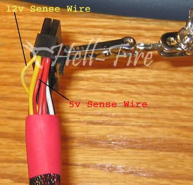
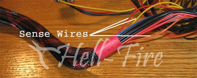
Now that you know what you are looking for, go to the top of the ATX connector bundle and find the same wires. Some modders prefer to cut the sense wires inside the psu housing, but I prefer to cut the sense wires outside of the housing as if a mistake is made you still have wire left to work with. Also, cutting the wires inside the housing can make soldering in that tight spot a chore for the inexperienced modder.
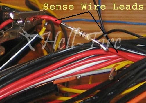
A pic showing the sense wires near the psu housing:
Cut away about and inch or so from each sense wire so that we can begin modding.
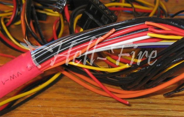
Here is where we want to go ahead and slide our shrink tubing over the sense wires so that after soldering is done we can protect our solder joints and prevent short circuits. If you do not add the shrink tubing at this time, you will not be able to add it later and will have to use another method to close off the solder joints.
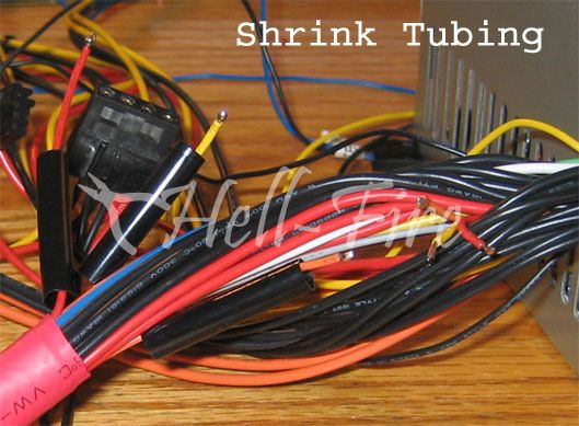
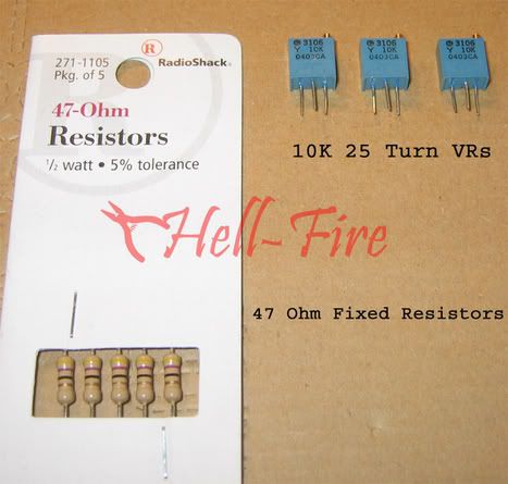
Between these sense wire leads is where we want to add our fixed resistors. I use a 47 ohm fixed resistor. No particular reason why, its just because they can be bought local to me. I recommend using a fixed resistor between 40-70 ohms.
Here is a pic of the 47 ohm fixed resistors I used, as well as the 10K VRs:
Cut the fixed resistor to fit between the sense wire leads, leaving one end with a bit of a longer leg. We will need that extra room in a bit.

Solder the fixed resistor in place. Be careful not to melt thru any of the surrounding insulation around the other wires.
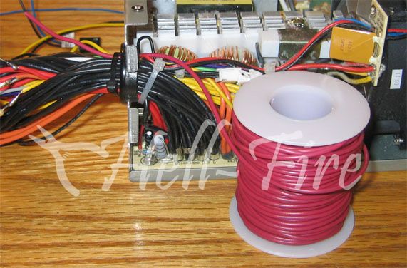
Now, we want to add a wire to the top leg of that fixed resistor. Top leg meaning the leg that is connected to the sense wire lead that goes into the psu housing. Since I am mounting my VRs inside the psu housing, it is better to run the wire from the inside of the psu, and to the fixed resistor.
I would suggest a wire length of around 10 inches if you plan on mounting the VRs inside the psu housing. If your wires are to short, you will have a hard time mounting the VRs and also removing the top of the housing should you need to get inside the psu at a later time. A flip side to that is that if the wires are to long, you may end up not being able to close the housing properly. This can force wires into the fan paths, or other problems where the wires may be putting pressure on other internal components.
It is much easier to solder that wire to the resistor leg if we strip enough of the insulation off so that we can wrap the exposed copper around the leg.
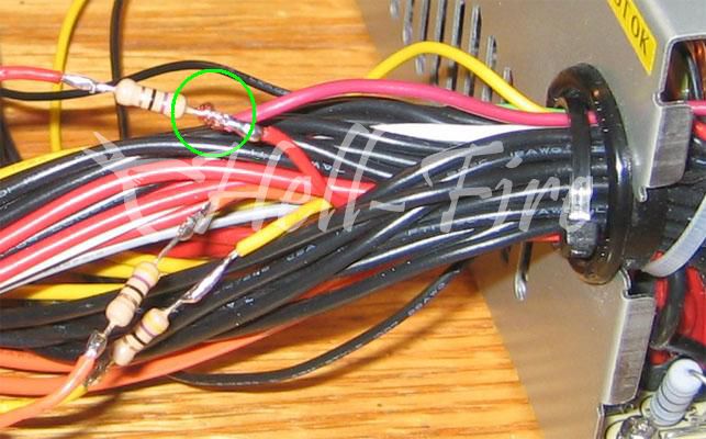
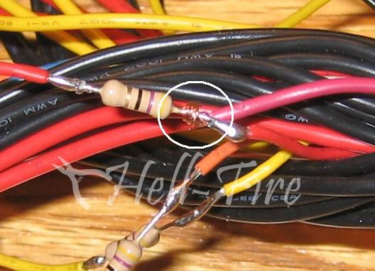
Simply apply solder to securely attach the wire to the resistor.
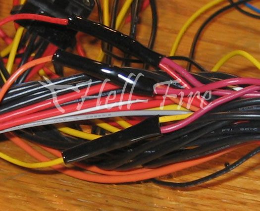
After you have attached all of the wires to the resistors, you will now want to apply heat to the shrink tubing so we can secure our solder joints. I use a heat gun for this, but a candle, lighter, hair dryer can be used. Be sure not to apply to much direct heat as you can easily melt this tubing off.
At this step we are now ready to attach our VRs to those wires we just added to the fixed resistors. To prepare the VRs for the mod, you should cut off one of the outter legs...leaving the middle leg and ONE outter leg. The reason is that only 2 legs are needed, and you MUST use the middle leg. I also cut away about 1/2 of the remaining legs to make things easier come soldering time.
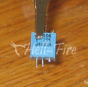
You also have to set the VRs to max resistance before soldering them in place. That is yet another good reason to remove one of the outter legs. It prevents you from making the mistake of setting max resistance between 2 legs, but soldering to the improper leg afterwards and having a zero resistance when you fire the psu on.
When attaching the wires, it does not matter which leg on the VR that you use, but I typically use the middle leg as my "hot" leg in the circuit.
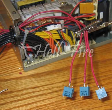
You are now ready to attach the wires to the VRs that will serve as the GND wires. These wires should be about 7 inches long.
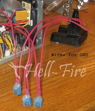
You should note the hot glue on the VRs. I recommend using something there to help protect the VRs legs as some force will be put on them. You will be twisting the wires while mounting the VRs, and things of that nature. It would be fairly easy to pop a VRs leg off after a few twists. The hot glue provides fantastic strength for the VRs. After soldering the GND wires onto the VRs, covering the solder joints and moving slightly up the wires will make yanking on the VRs a much safer thing to do.
Now that these are attached we can solder them in place to complete the circuit. You can use many things as a GND, but I prefer to solder directly to the GND wires running off the psu pcb. These are easy to get to:
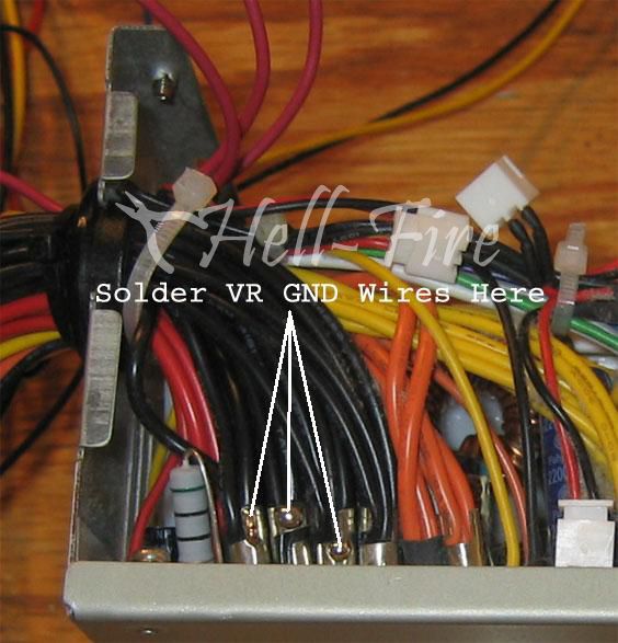
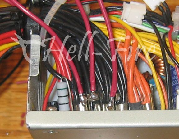
We are on the home stretch, so hang in there.
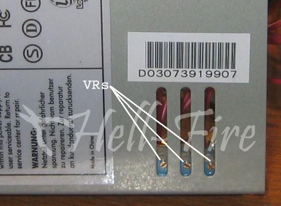
The easy place to mount the VRs is on the inside of the top of the psu housing. Typically, this is the side where the companies place the sticker stating what each rail is capable of, etc etc. There should be ventilation holes on that side that can be used for easy adjustment of the VRs after mounting.
**If your psu does not have vent holes present, you will have to drill holes in the side in order to have the ability to adjust the VRs.**
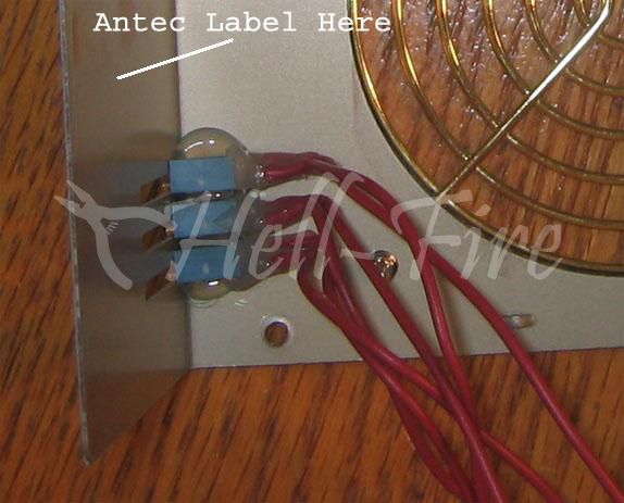
You can see in this pic how easy it is to adjust the VRs when you use this method:
Testing:
In order to test out the psu to make sure the mods are working properly, I recommend not plugging it into a motherboard. We can fire up the psu by bridging the proper wires on the ATX Connector. This allows us to safely check and adjust the voltage rails to our liking without the risk of burning a component.
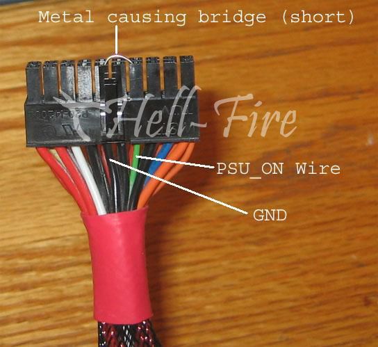
Depending on which outter leg you used, turning the VRs CW or CCW will increase your voltage now. I prefer to setup my VRs so that CW increases my voltage and CCW decreases it.
Grab ye olde trusty DMM and plug the leads into a molex connector (plugs into a hard drive or fan). Plug the black probe into a slot that has a black wire running into it, and the red probe into a slot with either the yellow or red wire running into it.
Start turning the screw on the VR and watch your voltage climb. Be aware that you may need a few turns to show a voltage rise, so be patient. If you start tuning it to fast the DMM may not be keeping up and you could kick in the psu's OVP which shuts the psu down. If this should happen, unplug or use the psu's on/off swtich and power it down. Turn the VR the opposite direction you were just turning a few turns. Let it sit for a few seconds, then power it back on.
You are now finished with the psu sense wire mod.

Please, note: XS owners and members will not be liable for any damage caused to you or your hardware, neither can be liable for any breach of the warranty.
!!!Remember that even when your computer power supply is off, it has enough current stored in it to kill you. The information presented here is for illustration purposes only. Use it at you own risk.!!!
I've uploaded and changed the links to the origional pictures - Persivore.
Last edited by persivore; 07-31-2005 at 04:11 AM.
 Posting Permissions
- You may not post new threads
- You may not post replies
- You may not post attachments
- You may not edit your posts
-
Forum Rules


 Reply With Quote

Bookmarks