Page 1 of 10 1234 ... LastLast
Results 1 to 25 of 230

Thread: Guide: Power Supply Sense Wire Modding

  1. #1
    Xtreme Mentor
    Join Date
    May 2003
    Location
    Engineering Lab - NCSU
    Posts
    2,978

    Guide: Power Supply Sense Wire Modding

    Please, note: XS owners and members will not be liable for any damage caused to you or your hardware, neither can be liable for any breach of the warranty.

    !!!Remember that even when your computer power supply is off, it has enough current stored in it to kill you. The information presented here is for illustration purposes only. Use it at you own risk.!!!


    I have received many a PM and Email asking about modding the sense wires on a power supply in order to grab higher rails. I am sure many other members have as well.

    To keep from having to say the same thing over and over again, I have put together a guide that should work for any power supply. I have modded the PCP&C, Antec, Enermax, Aspire, and various other supplies. This mod has worked for every single one of them.

    This mod also works if your psu already has internal pots available, but you would like to increase your rails past what the stock pots allow.

    Not all power supplies have sense wires, but most do atleast have a sense wire for the 3.3v rail. Also, most power supplies that have a 5v sense wire, but no 12v sense wire are still moddable. In this situation, modding the 5v sense wire will a vast majority of the time mod the 12v rail as well.

    This guide was written while modding an Antec TP430.

    Abbreviations and other things that may be useful in order to follow this guide more easily:

    VR = Variable Resistor (Pot or Trimmer)
    PSU = Power Supply
    DMM = Digital Multimeter
    CW = Clockwise
    CCW = Counter-Clockwise
    Red Wires in PSU = 5v Rail
    Orange Wires in PSU = 3.3v Rail
    Yellow Wires in PSU = 12v Rail

    ==============================================

    Materials Needed:

    40-70 Ohm Fixed Resistor
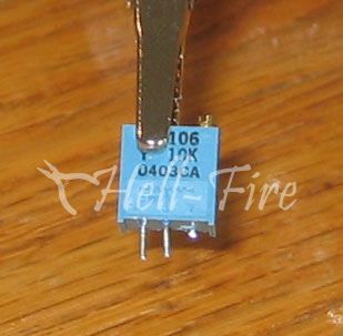
    10K Multi-Turn VR
    Rosin-Core Solder
    Solder Iron (25 watt is recommended)
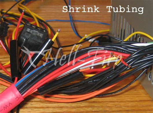
    Shrink Tubing
    Wire Cutters/Strippers
    Hot Glue/Epoxy/Super Glue

    Procedure:

    Make sure your psu is unplugged from the wall and if it has an on/off swtich, be sure that is set to off as well.

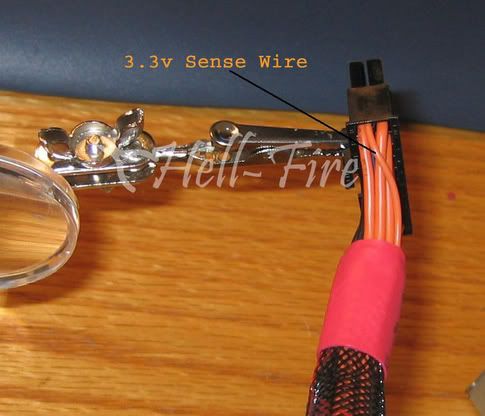
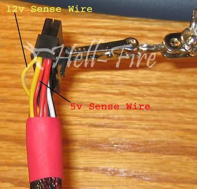
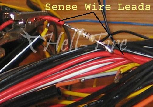
    Grab the ATX Connector and look at the 4 corners. One end will have 2 think orange wires running into the corner slots, the other corners will have a thick red and a thick yellow wire running into them. There will also be thinner wires running into the same slots. These thinner wires are the sense wires.

    **Note that only one of the thick orange wires will have an accompanying sense wire while the other thick orange wire is alone in its slot. Also note that sometimes the sense wire for the 3.3v rail is brown.**


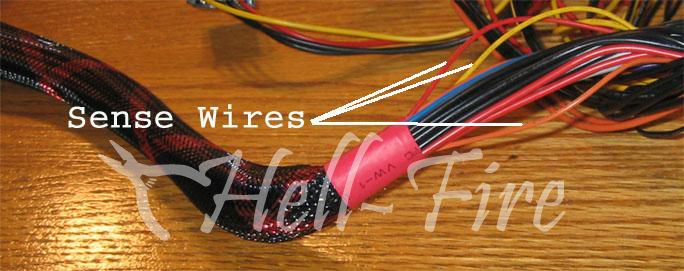
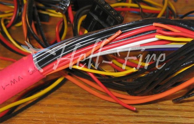
    Now that you know what you are looking for, go to the top of the ATX connector bundle and find the same wires. Some modders prefer to cut the sense wires inside the psu housing, but I prefer to cut the sense wires outside of the housing as if a mistake is made you still have wire left to work with. Also, cutting the wires inside the housing can make soldering in that tight spot a chore for the inexperienced modder.

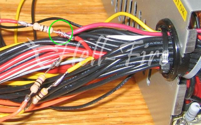
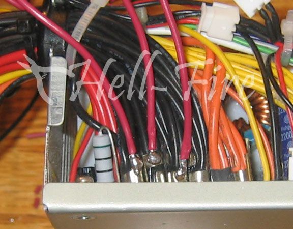
    A pic showing the sense wires near the psu housing:


    Cut away about and inch or so from each sense wire so that we can begin modding.


    Here is where we want to go ahead and slide our shrink tubing over the sense wires so that after soldering is done we can protect our solder joints and prevent short circuits. If you do not add the shrink tubing at this time, you will not be able to add it later and will have to use another method to close off the solder joints.


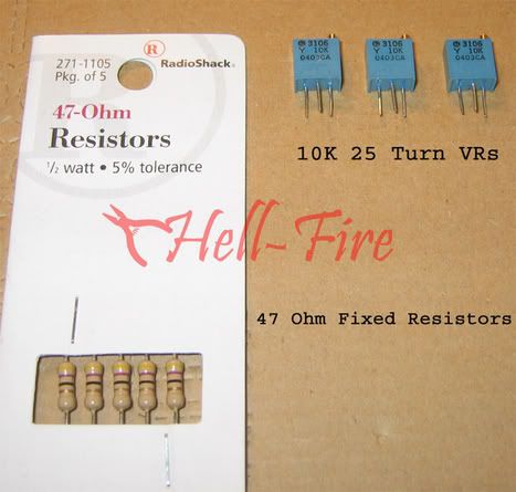
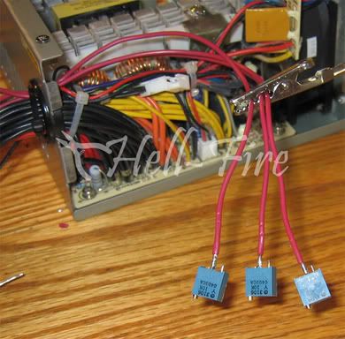
    Between these sense wire leads is where we want to add our fixed resistors. I use a 47 ohm fixed resistor. No particular reason why, its just because they can be bought local to me. I recommend using a fixed resistor between 40-70 ohms.

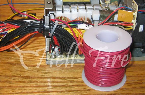
    Here is a pic of the 47 ohm fixed resistors I used, as well as the 10K VRs:


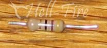
    Cut the fixed resistor to fit between the sense wire leads, leaving one end with a bit of a longer leg. We will need that extra room in a bit.


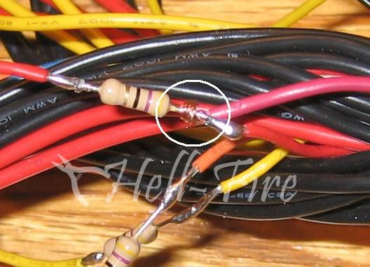
    Solder the fixed resistor in place. Be careful not to melt thru any of the surrounding insulation around the other wires.


    Now, we want to add a wire to the top leg of that fixed resistor. Top leg meaning the leg that is connected to the sense wire lead that goes into the psu housing. Since I am mounting my VRs inside the psu housing, it is better to run the wire from the inside of the psu, and to the fixed resistor.

    I would suggest a wire length of around 10 inches if you plan on mounting the VRs inside the psu housing. If your wires are to short, you will have a hard time mounting the VRs and also removing the top of the housing should you need to get inside the psu at a later time. A flip side to that is that if the wires are to long, you may end up not being able to close the housing properly. This can force wires into the fan paths, or other problems where the wires may be putting pressure on other internal components.


    It is much easier to solder that wire to the resistor leg if we strip enough of the insulation off so that we can wrap the exposed copper around the leg.


    Simply apply solder to securely attach the wire to the resistor.

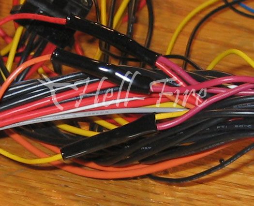
    After you have attached all of the wires to the resistors, you will now want to apply heat to the shrink tubing so we can secure our solder joints. I use a heat gun for this, but a candle, lighter, hair dryer can be used. Be sure not to apply to much direct heat as you can easily melt this tubing off.


    At this step we are now ready to attach our VRs to those wires we just added to the fixed resistors. To prepare the VRs for the mod, you should cut off one of the outter legs...leaving the middle leg and ONE outter leg. The reason is that only 2 legs are needed, and you MUST use the middle leg. I also cut away about 1/2 of the remaining legs to make things easier come soldering time.


    You also have to set the VRs to max resistance before soldering them in place. That is yet another good reason to remove one of the outter legs. It prevents you from making the mistake of setting max resistance between 2 legs, but soldering to the improper leg afterwards and having a zero resistance when you fire the psu on.

    When attaching the wires, it does not matter which leg on the VR that you use, but I typically use the middle leg as my "hot" leg in the circuit.


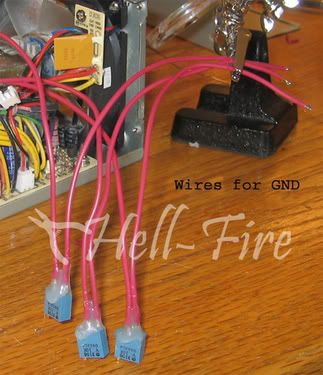
    You are now ready to attach the wires to the VRs that will serve as the GND wires. These wires should be about 7 inches long.


    You should note the hot glue on the VRs. I recommend using something there to help protect the VRs legs as some force will be put on them. You will be twisting the wires while mounting the VRs, and things of that nature. It would be fairly easy to pop a VRs leg off after a few twists. The hot glue provides fantastic strength for the VRs. After soldering the GND wires onto the VRs, covering the solder joints and moving slightly up the wires will make yanking on the VRs a much safer thing to do.

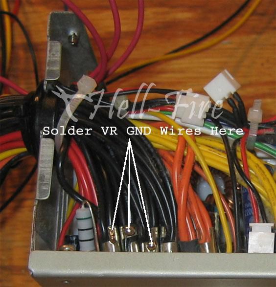
    Now that these are attached we can solder them in place to complete the circuit. You can use many things as a GND, but I prefer to solder directly to the GND wires running off the psu pcb. These are easy to get to:


    We are on the home stretch, so hang in there.

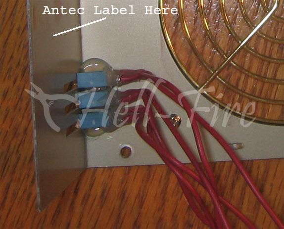
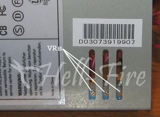
    The easy place to mount the VRs is on the inside of the top of the psu housing. Typically, this is the side where the companies place the sticker stating what each rail is capable of, etc etc. There should be ventilation holes on that side that can be used for easy adjustment of the VRs after mounting.

    **If your psu does not have vent holes present, you will have to drill holes in the side in order to have the ability to adjust the VRs.**


    You can see in this pic how easy it is to adjust the VRs when you use this method:


    Testing:

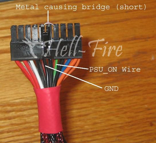
    In order to test out the psu to make sure the mods are working properly, I recommend not plugging it into a motherboard. We can fire up the psu by bridging the proper wires on the ATX Connector. This allows us to safely check and adjust the voltage rails to our liking without the risk of burning a component.


    Depending on which outter leg you used, turning the VRs CW or CCW will increase your voltage now. I prefer to setup my VRs so that CW increases my voltage and CCW decreases it.

    Grab ye olde trusty DMM and plug the leads into a molex connector (plugs into a hard drive or fan). Plug the black probe into a slot that has a black wire running into it, and the red probe into a slot with either the yellow or red wire running into it.

    Start turning the screw on the VR and watch your voltage climb. Be aware that you may need a few turns to show a voltage rise, so be patient. If you start tuning it to fast the DMM may not be keeping up and you could kick in the psu's OVP which shuts the psu down. If this should happen, unplug or use the psu's on/off swtich and power it down. Turn the VR the opposite direction you were just turning a few turns. Let it sit for a few seconds, then power it back on.

    You are now finished with the psu sense wire mod.


    Please, note: XS owners and members will not be liable for any damage caused to you or your hardware, neither can be liable for any breach of the warranty.

    !!!Remember that even when your computer power supply is off, it has enough current stored in it to kill you. The information presented here is for illustration purposes only. Use it at you own risk.!!!


    I've uploaded and changed the links to the origional pictures - Persivore.
    Last edited by persivore; 07-31-2005 at 04:11 AM.

  2. #2
    Xtreme Member
    Join Date
    Nov 2003
    Posts
    159

    Thumbs up

    this guide rules, very clean work and informative

  3. #3
    Xtreme Mentor
    Join Date
    May 2003
    Location
    Engineering Lab - NCSU
    Posts
    2,978
    Originally posted by enduracell
    this guide rules, very clean work and informative
    TY Sir.

    Took me a couple of hours between doing the actual modding, taking hte pics along the way, and editing the pics.

    Hope it helps those who are diving into the Vmod realm so to speak.


    I like my women the way I like my processors...naked.
    I am not the HellFire that writes bios files. I work strictly on voltage modifications.

  4. #4
    Xtreme Mentor
    Join Date
    Jan 2004
    Location
    Berkeley/Stanford, CA, USA
    Posts
    2,611
    wow i like how u took pics of everything, i think im gonna dapt some of ur methods, like using hotglue, to secure wires in place

    can you see the light? is it shining too bright? can you see the light at the end of the tunnel, i know i do, i know its true.

  5. #5
    Xtreme X.I.P.
    Join Date
    Dec 2003
    Posts
    4,734
    Great guide, HF! excellent pictures, close-ups and parts descriptions
    you just can't stop impressing me with your commitment to this forum and all modding community here, can u ?
    with guys like you, Malves, Holst and others this is just the "bestest" place to hang out and gain experience...

    BTW, congrats to you guys on occasion of being promoted to moderators...

    Great work, once again... !!!

  6. #6
    Xtreme Mentor
    Join Date
    May 2003
    Location
    Engineering Lab - NCSU
    Posts
    2,978
    Thanks pc_ice, blinky, and bachus.

    I love this joint obviously. Take pride in helping its members, as well as being helped by its members.

    I consider this the best site on the net for overclocking/modding.


    I like my women the way I like my processors...naked.
    I am not the HellFire that writes bios files. I work strictly on voltage modifications.

  7. #7
    Xtreme Member
    Join Date
    Jan 2004
    Location
    Baku, Azerbaijan
    Posts
    164
    Well done! Very important guide!
    A64 FX55, Asus A8V DLX, 2X512MB OCZ EL GOLD PC4000, Asus AX800XT Water cooled!

  8. #8
    Xtreme Member
    Join Date
    Apr 2004
    Location
    Germany
    Posts
    213
    Excellent guide, well done

    I still have a question though - why is the fixed resistor needed? In the original thread 'bout the sense wire mod, nobody mentioned a fixed resistor...

    DFI NF4 Ultra-D @ 300HTT | A64 3000+ Winchester @ 2.4GHz 1.61V | 4x256MB BH-5 (HyperX+CorsairXMS) @ 240MHz 2-2-2-5 3.1V | Club3D X800XL ViVo @ 452/540 | XP-90 | 92mm Tornado | Silencer5 | Enermax 460W | 2k1: 30419

  9. #9
    Xtreme Mentor
    Join Date
    May 2003
    Location
    Engineering Lab - NCSU
    Posts
    2,978
    Originally posted by DarkManX_BG
    Excellent guide, well done

    I still have a question though - why is the fixed resistor needed? In the original thread 'bout the sense wire mod, nobody mentioned a fixed resistor...

    As far as I can recall, the Antec supplies need that fixed resistor or the mods will not function.

    I would say most supplies dont need the fixed resistor.

    Most of the earlier threads about psu modding had a fixed resistor used as well as the VR. Its prob more habit now with me than anything else. I remember doing my first psu mod and it didnt work without the fixed resistor. That was on my old Antec TP550. Now, it could have been that I didnt do the mod properly to begin with since I was a newb modder at that point, but I almost always use the fixed resistor to save time later on in case it doesnt work without it.

    The next supply I work on I will do it without the fixed resistor.

    I do know that most supplie do not require it, although I always add it.
    Last edited by Hell-Fire; 07-02-2004 at 05:55 AM.


    I like my women the way I like my processors...naked.
    I am not the HellFire that writes bios files. I work strictly on voltage modifications.

  10. #10
    Xtreme Enthusiast
    Join Date
    Nov 2003
    Location
    VIENNA
    Posts
    632
    excellent job there.


    How far was the 3.3v adjustable ?
    I currently have a Enermax 460 W that does well but Im looking for more :p
    Overclocking made in Austria

  11. #11
    Xtreme Member
    Join Date
    Dec 2003
    Location
    Over here!!
    Posts
    443
    If you love your computer...give it the juice it needs!!
    Excellent job Hell-Fire!!
    Not only did it stabilize my MB voltage, but I upped the voltage to the Vapo pump from 11.97 to 12.50v.
    Hell-Fire, you make it sooo simple, even a Rukee could do it.
    That`s not an easy task my friend.
    The world`s only triple phase-changer PC in one case.

  12. #12
    Xtreme Mentor
    Join Date
    May 2003
    Location
    Engineering Lab - NCSU
    Posts
    2,978
    Originally posted by EmineM
    excellent job there.


    How far was the 3.3v adjustable ?
    I currently have a Enermax 460 W that does well but Im looking for more :p

    That totally depends on the power supply in question.

    On mine, 4.1v is the max before OVP kicks in.


    Originally posted by Rukee
    If you love your computer...give it the juice it needs!!
    Excellent job Hell-Fire!!
    Not only did it stabilize my MB voltage, but I upped the voltage to the Vapo pump from 11.97 to 12.50v.
    Hell-Fire, you make it sooo simple, even a Rukee could do it.
    That`s not an easy task my friend.

    LOL, nice play on words bro.

    Glad to hear you got her rolling. Now kick that Vapo in the arse and lets see some ridiculous scores.


    I like my women the way I like my processors...naked.
    I am not the HellFire that writes bios files. I work strictly on voltage modifications.

  13. #13
    Banned
    Join Date
    May 2003
    Location
    Saskatoon,Sask.Canada
    Posts
    14
    hi hellfire.excellent guide.has anyone considered mounting the 92mm intake fan on the psu,outside the psu.this would i think,give you a little extra room for the wiring,and also having the fan back that little bit could give more cooling power,as basically it is right close to the heatsinks on the psu,then perhaps less of a deadspot from the fan.

  14. #14
    Xtreme Mentor
    Join Date
    May 2003
    Location
    Engineering Lab - NCSU
    Posts
    2,978
    I am sure that would work in fact.

    Had a few people request I do it that way for them when modding their psu's.

    Its a system dependent thing tho as some setups need the room under the psu.


    I like my women the way I like my processors...naked.
    I am not the HellFire that writes bios files. I work strictly on voltage modifications.

  15. #15
    Banned
    Join Date
    May 2003
    Location
    Saskatoon,Sask.Canada
    Posts
    14
    THANK YOU HELLFIRE!!!.i finally got my antec truepower 550 voltmodded today .i went step by step using your guide & it worked out great.i did put the 92mm panaflo i had swapped out previously,outside the psu.that gave me some extra room for the trimmers.if it will work in peoples cases do it,it feels like the amount of air being exhausted is at least 33% more.i did the mods one at a time,powered up the psu & metered it.right now i have the 12v@ 12.25,5v@ 5.25.when i metered the 3.3 line it was reading 3.36 off the atx connector great i thought,before it was always stuck at 3.28-3.29v.i booted it up,and the 3.3 line is still reading 3.29.the bios is reading the 5 & 12 voltages properly.
    .what i did notice is that it took a lot of turns on the trimmers.12v & 5v,before the voltage started climbing. fyi i used 22ga stranded wire.i will have to shut the puter off so i can try and up the 3.3v line & see what happens.i will post back if i am successful or not
    thank you again

  16. #16
    Xtreme Member
    Join Date
    May 2004
    Posts
    138
    Best powersupply Vmod guide out there, hands down(or at least that i have been about to find)

    great work as usaual fire. nice pics. very informative. one quetion thought. are the fixed resitors needed? i am running them on all my modded PSU's. just curious. but i suppose if they wernt needed you wouldnt have them
    Last edited by jess1313; 07-02-2004 at 05:46 AM.
    DFI NF3-250 LanParty UT A64 3200 1m DTR @2550(10x255) - mushkin 222 -3dmark01 - 26424
    Shuttle SN85G4 V2 - A64 3200 1m @2525(10x252) - mushkin 222- 9800pro -3Dmark01 - 26379
    DFI Ultra B - 2600+ Mobile@2604(10.5x248) - mushkin 222 - 9800pro - 3Dmark01 - 21445
    Abit NF7 - 2600+Mobile@2520(10.5x240) - mushkin 222- 9800pro- 3Dmark01 - 21166.
    DFI P5BV3+ - K6-III+ 450@600(6x100)@2.4 vcore - Ati 8500 - 2x 4gb Quantan FireBall


    *DFI NF3-250GB UT Beta Bioses w/ 4.0vdimm and works w/ mobiles*
    *NF7 modded BIOS Vault*
    *If you have a DFI NFII MoBo read this
    *

  17. #17
    Xtreme Mentor
    Join Date
    May 2003
    Location
    Engineering Lab - NCSU
    Posts
    2,978
    Originally posted by rj2
    THANK YOU HELLFIRE!!!.i finally got my antec truepower 550 voltmodded today .i went step by step using your guide & it worked out great.i did put the 92mm panaflo i had swapped out previously,outside the psu.that gave me some extra room for the trimmers.if it will work in peoples cases do it,it feels like the amount of air being exhausted is at least 33% more.i did the mods one at a time,powered up the psu & metered it.right now i have the 12v@ 12.25,5v@ 5.25.when i metered the 3.3 line it was reading 3.36 off the atx connector great i thought,before it was always stuck at 3.28-3.29v.i booted it up,and the 3.3 line is still reading 3.29.the bios is reading the 5 & 12 voltages properly.
    .what i did notice is that it took a lot of turns on the trimmers.12v & 5v,before the voltage started climbing. fyi i used 22ga stranded wire.i will have to shut the puter off so i can try and up the 3.3v line & see what happens.i will post back if i am successful or not
    thank you again

    No worries bud, thats why I am here.

    Yeh, it can take a few turns sometimes to get the voltages to start moving. They start to increase faster after that so be careful.

    The increase you saw on the 3.3v rail, regardless of the VR bing there, is from the fixed resistor. If you do not get any further increase after adjusting the 3.3v VR, better take a look at the solder joints for that rail, and the ground point of the 3.3v VR as well.


    Originally posted by jess1313
    great work as usaual fire. nice pics. very informative. one quetion thought. are the fixed resitors needed? i am running them on all my modded PSU's. just curious. but i suppose if they wernt needed you wouldnt have them

    I cant be certain, but I am fairly sure that on the Antec supplies the fixed resistor is needed or the mods will not work. I generally add them just so I dont have to redo the mods if they dont work because I only used a VR versus both.

    I do know that not all supplies need the fixed inline with the VR. I pretty much use the fixed to keep from getting a headache afterwards.

    I have a supply that someone sent me for my testing bench. I will do the 3.3v mod on it if a sense wire is present. Let you know how it responded without using the fixe resistor.

    The next Antec I get, I will do the mod without the fixed as well and see what happens.


    I like my women the way I like my processors...naked.
    I am not the HellFire that writes bios files. I work strictly on voltage modifications.

  18. #18
    Banned
    Join Date
    May 2003
    Location
    Saskatoon,Sask.Canada
    Posts
    14
    then for your help about the 3.3 line.i have`nt taken the psu out yet.i grounded the neg,to the same place in your pix.i tinned the soldering iron every time,and made sure it was a clean connection.ill go back and recheck it tho.

  19. #19
    Xtreme Mentor
    Join Date
    May 2003
    Location
    Engineering Lab - NCSU
    Posts
    2,978
    Originally posted by rj2
    then for your help about the 3.3 line.i have`nt taken the psu out yet.i grounded the neg,to the same place in your pix.i tinned the soldering iron every time,and made sure it was a clean connection.ill go back and recheck it tho.
    As ridiculous as this will sound, be sure you are using seperate grounds for everything.

    Although everything is technically using the same ground, using the actual exact same grounding point can cause weird issues.


    I like my women the way I like my processors...naked.
    I am not the HellFire that writes bios files. I work strictly on voltage modifications.

  20. #20
    Banned
    Join Date
    May 2003
    Location
    Saskatoon,Sask.Canada
    Posts
    14
    i used 3 seperate grnd points.i put a dab of solder on 3 of the pieces of steel in your pix that are holding the grnd wires coming from the pcb.then touched the grnd wire to the solder blob.clean as a whistle soldering wise.

  21. #21
    Xtreme Mentor
    Join Date
    May 2003
    Location
    Engineering Lab - NCSU
    Posts
    2,978
    Should be working fine then I would think.


    I like my women the way I like my processors...naked.
    I am not the HellFire that writes bios files. I work strictly on voltage modifications.

  22. #22
    Banned
    Join Date
    May 2003
    Location
    Saskatoon,Sask.Canada
    Posts
    14
    me again.in the end i was`nt turning the trimmer enough.i have got it up to 3.4 0n the 3.3 line.the weirdest thing is that the bios and mbm still read it as 3.29.i cant figure that out.but at least i know my soldering job and what not was good

  23. #23
    Registered User
    Join Date
    Sep 2003
    Location
    belgium
    Posts
    43
    bios readings aren't always accurate, always use a multimeter
    3200 winchester / 2*256 winbond UTT Mtec 50D - 2*256 Twinmos BH-5 - 1*256mb Corsair XMS 3500v1.1 BH-5 / EP-9NDA3+ Vdimm modded / R9800NP

  24. #24
    Banned
    Join Date
    May 2003
    Location
    Saskatoon,Sask.Canada
    Posts
    14
    i agree.very strange tho that the bios is still misreading the 3.3volt line but is reading the 5.5 & 12 lines properly

  25. #25
    Xtreme Mentor
    Join Date
    May 2003
    Location
    Engineering Lab - NCSU
    Posts
    2,978
    Definitely use a DMM when adjusting the VRs...never trust the bios for an accurate reading on any voltage.


    I like my women the way I like my processors...naked.
    I am not the HellFire that writes bios files. I work strictly on voltage modifications.

Page 1 of 10 1234 ... LastLast

Bookmarks

Bookmarks

Posting Permissions

  • You may not post new threads
  • You may not post replies
  • You may not post attachments
  • You may not edit your posts
  •