Results 1 to 18 of 18

Thread: IT7 Vcore Mod Help

  1. #1
    Xtreme Addict
    Join Date
    Jun 2002
    Location
    Melbourne, Australia
    Posts
    1,118

    IT7 Vcore Mod Help

    I know this is the wrong forum guys and i apologise. Feel free to move but keep the link so pple can see it cos more people visit this forum that the mobo vmod one...

    Thanks to Chong for helping me out via PM before...

    I have just done the vcore mod to the board and have used 2 wires and a 50K pot with a turning dial on it. Pretty much the same setup as the kr7a mod i did a few months ago.

    I have 3 pin type things on the pot stickig up and the wire going to the ic chip Pin7 is connected to one of the outside pins and the ground wire is connected to the middle pin and the other outer one is free.

    I have used a 3 plug fan thingie like in the Mricee guide and plugged it up to a fan header. The ground wire is connected to where the black one would usually be on the fan header thingie and i boot the pc. The bios is set to 1.50 and the vcore reads 1.37 with the pot turned all way to the RIGHT. I turn a little to LEFT and it increases to 1.45 (where it usualy sits at 1.50 setting) and then i keep turning and turning and it doesnt change.

    This happens for every bios setting and then when I use 1.6 and above, when its turned all way to RIGHT it works cos it goes to about .7 below what its set to and then i turn the dial and it rises and then i turn some more and the pc shuts off? This happens also when i turn the dial quickly going up or down asd well


    I have done evevrything right but it wont work... Can anyone please help me cos now i have a wire soldered to my pin7 on the ic chip and can only get a max of 1.64 volts real. I have taken the pin mod off the cpu like Opp told me to and I can go only go to 1.7 in bios. With pin done, I can get to 1.85.

    Anyone??!!!


    [EDit: Attached Pics]

    This is the axtual mod job


    This is the Mod again but blurry


    This is the fan connecter and i twisted the ground wire around this one and used electric tape for now to hold till my friend can solder again...


    The Mod in full
    Last edited by Creative; 09-08-2002 at 02:50 AM.

    Intel P4 3.2 EE || Asus P4C800-E || Prometia Mach II || 2 x 256Meg HyperX 3500 || Antec TrueControl|| Sapphire Radeon 9800XT || 2x Raptors || Samsung 172T

    OCAU 3DMark Team || 3DMark Compare: 26847 || World of Britney|| PCDB Entry

    "Sundance is weird. The movies are weird. You actually have to think about them when you watch them. " -Britney Spears

  2. #2
    Registered User
    Join Date
    Sep 2002
    Location
    CT
    Posts
    28
    Creative-
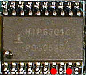
    I maybe going blind (my mom warned me that would happen if I did'nt stop....oh never mind) but it looks to me like you got your lead soldered to the wrong pin. I'm looking at my KR7A-Raid and my KX7333-Raid, and both have the HIP6301CB vr chip. On both these boards- the 7th pin is on the lower set of pins-so the indentation on the chip is on the left side and the letters on the chip are rightside up. Like this:
    http://www.ocinside.de/index_e.html?...kshop/socketa/
    Please double check what I've said as I am having a hard time reading the label on the VR from your pics-!!

    Having a tough time with the URL but-look under the workshop section, KR7A vcore guide.
    Last edited by RAMMER; 09-08-2002 at 05:12 PM.

  3. #3
    Xtreme Legend
    Join Date
    Jun 2002
    Location
    Hong Kong
    Posts
    3,289
    RAMMER is absolutely right. You are using pin 17 instead of 7.

    Small wonder you haven't fried the board.

    DDTUNG

  4. #4
    Xtreme Member
    Join Date
    Jun 2002
    Location
    Rio de Janeiro, Brazil
    Posts
    127
    wowowow..
    looks like the it7 DOT is not in the same position as in Kr7a,etc..

    look close.. the dot on creative chip is in the TOP RIGHT..
    on others is on the LEFT BOTTON.. wtf??!?

    creative did soldered on pin 7.. acording pin 7 should be the 7th anti-clock wise pin after the dot!

    so i think the thing is.. should be on the 7th botton pin (on the right off the chip)..

    like this pic :


    thats a good info.. i was going to volt mod mine tomorow (pin mod suck).. gonna see where is my dot..eheh

  5. #5
    Registered User
    Join Date
    Sep 2002
    Location
    CT
    Posts
    28
    My KX7 has the indent in the middle (half moon) like Creative's-my IT7 has it on the lower corner(small circle). It should not matter what shape -in respect to the markings on the IC. The half moon or circle denotes the left side and the chips lettering is right side up as such. Just like the attached picture in UaZa's post.

  6. #6
    Xtreme Addict
    Join Date
    Jun 2002
    Location
    Melbourne, Australia
    Posts
    1,118
    I followed the pics in the IT7 vcore mod thread in the Mobo Volt mods forum. The pic that I was copying is below. AFAIK I have everything in the correct position. Or is this board in the picture not a IT7?

    Maybe chong or OPP could check thier IT7 mods and check for me please?

    Intel P4 3.2 EE || Asus P4C800-E || Prometia Mach II || 2 x 256Meg HyperX 3500 || Antec TrueControl|| Sapphire Radeon 9800XT || 2x Raptors || Samsung 172T

    OCAU 3DMark Team || 3DMark Compare: 26847 || World of Britney|| PCDB Entry

    "Sundance is weird. The movies are weird. You actually have to think about them when you watch them. " -Britney Spears

  7. #7
    Xtreme Member
    Join Date
    Jul 2002
    Location
    Naples, Italy
    Posts
    121
    Creative, you are in the wrong side

    you should be here :

    Last edited by DDA; 09-08-2002 at 10:33 PM.

  8. #8
    Xtreme Addict
    Join Date
    Jun 2002
    Location
    Melbourne, Australia
    Posts
    1,118
    How can you say that though? Look at my top pic in my first post and the bottom pic in the last post, they have the capasitators the same side and stuff and the orientation of the chip looks the same?

    Is the chip in the it7 upside down and these pics I was using as a guide are for the KR7A and is around a different way? The writing on the pics given compared to the solder is upside down and its also upside down to my soldered pin also so they should be the same?

    Soz for being sounding like a n00b but I was pretty sure it was all done correct... Everyone just said to look at Mr Icees guide and stuff, they never said it was different for Intel boards compared to AMD boards.
    Last edited by Creative; 09-08-2002 at 10:20 PM.

    Intel P4 3.2 EE || Asus P4C800-E || Prometia Mach II || 2 x 256Meg HyperX 3500 || Antec TrueControl|| Sapphire Radeon 9800XT || 2x Raptors || Samsung 172T

    OCAU 3DMark Team || 3DMark Compare: 26847 || World of Britney|| PCDB Entry

    "Sundance is weird. The movies are weird. You actually have to think about them when you watch them. " -Britney Spears

  9. #9
    Xtreme Legend
    Join Date
    Jun 2002
    Location
    Hong Kong
    Posts
    3,289

    Smile Creative

    The dot on the chip is always next to pin 1. Whoever put up that pic in the thread was wrong.

    Pin 17 that you used is SS(soft start).

    DDTUNG

  10. #10
    Xtreme Addict
    Join Date
    Aug 2002
    Location
    Melbourne Aus
    Posts
    1,219
    whoever put up that pic needs to be shot..

    pfft one day's work all down the drain..

    DDTUNG wanna point out which pin acutally needs to be soldered (if u could point it out on the pic creative posted it would be great)

  11. #11
    Xtreme Addict
    Join Date
    Jun 2002
    Location
    Melbourne, Australia
    Posts
    1,118
    Many many thansk for that DDTUNG

    so the IT7 vcore mod needs to be on the pins on the top pins of the chip when looking at the board and not the bottom side of the chip like in that Guide?

    If its wrong then yep in that thread they are wrong pics and the person who posted them should be held responsible if my board dies
    hehehehe

    [Edit: This here is my soldering buddy Ragnarok ]
    hehehehe

    Intel P4 3.2 EE || Asus P4C800-E || Prometia Mach II || 2 x 256Meg HyperX 3500 || Antec TrueControl|| Sapphire Radeon 9800XT || 2x Raptors || Samsung 172T

    OCAU 3DMark Team || 3DMark Compare: 26847 || World of Britney|| PCDB Entry

    "Sundance is weird. The movies are weird. You actually have to think about them when you watch them. " -Britney Spears

  12. #12
    Xtreme Member
    Join Date
    Jul 2002
    Location
    Naples, Italy
    Posts
    121
    creative
    look at the pic above, showing the correct pin 7 you hv to solder on
    Last edited by DDA; 09-08-2002 at 10:39 PM.

  13. #13
    Xtreme Legend
    Join Date
    Jun 2002
    Location
    Hong Kong
    Posts
    3,289
    Here's the simple rule for pin identification:

    The dot is always next to pin 1. The pins are numbered 1,2,3,4,...as you count clockwise. When they use the notch instead of the dot, pin 1 is to the left of the notch with the notch pointing up. If you follow this rule, you can't go wrong.

    DDTUNG

  14. #14
    Xtreme Addict
    Join Date
    Jun 2002
    Location
    Melbourne, Australia
    Posts
    1,118
    Originally posted by DDA
    creative
    look at the pic above, showing the corect pin 7 yuo hv to solder on
    Thanks heaps for that DDA for the pic and DDTUNG for the advice as to where Pin1 is on the chips. Its a valuable source of info that I will not forget...kinda like how IDE cables can only go in one way etc....
    hehehe

    Ill go to Rags house tonight and we will fix it up. Least I know now 100% the correct pin and now I have confidence it will work...

    Thanks again guys, thread can be locked or shut now if you want..

    Creat

    Intel P4 3.2 EE || Asus P4C800-E || Prometia Mach II || 2 x 256Meg HyperX 3500 || Antec TrueControl|| Sapphire Radeon 9800XT || 2x Raptors || Samsung 172T

    OCAU 3DMark Team || 3DMark Compare: 26847 || World of Britney|| PCDB Entry

    "Sundance is weird. The movies are weird. You actually have to think about them when you watch them. " -Britney Spears

  15. #15
    Xtreme Addict
    Join Date
    Aug 2002
    Location
    Melbourne Aus
    Posts
    1,219
    thanx

    we will fix it up creat..

    now will the person who posted the wrong mod pic please stand up

    edit: btw the dot u refer to on the top right of creat's weird chip is acutally a tiny tiny bit of solder me thinks
    Last edited by Ragnarok; 09-08-2002 at 10:46 PM.

  16. #16
    Xtreme Addict
    Join Date
    Jun 2002
    Location
    Melbourne, Australia
    Posts
    1,118
    We did it again yesterday and now its working...

    I can go up to 1.92 volts before the pc shuts down. Dont know if its an over voltage safety thing or temps cos its quite hot here today unfortunantly so will have to wait to see if it cools down tonight...

    At 1.85 set in bios I get 1.87idle in Windows and then it undervolts t 1.81 in window priming. Im happy that it works cos now I might get some more mhz out of this cpu.....

    Pity we are starting to get hot weather....I need a prometia so weather doesnt make a difference :p
    heheheh

    Intel P4 3.2 EE || Asus P4C800-E || Prometia Mach II || 2 x 256Meg HyperX 3500 || Antec TrueControl|| Sapphire Radeon 9800XT || 2x Raptors || Samsung 172T

    OCAU 3DMark Team || 3DMark Compare: 26847 || World of Britney|| PCDB Entry

    "Sundance is weird. The movies are weird. You actually have to think about them when you watch them. " -Britney Spears

  17. #17
    Xtreme Addict
    Join Date
    Aug 2002
    Location
    Melbourne Aus
    Posts
    1,219
    w00t it works !

  18. #18
    Member
    Join Date
    Jun 2002
    Location
    Glendale/Irvine CA
    Posts
    130
    Originally posted by Ragnarok
    now will the person who posted the wrong mod pic please stand up
    Heh I'm hosting those pics but they're majormav's not mine. Funny he didn't say anything about it not working...good to hear it's resolved now though.

Bookmarks

Bookmarks

Posting Permissions

  • You may not post new threads
  • You may not post replies
  • You may not post attachments
  • You may not edit your posts
  •