

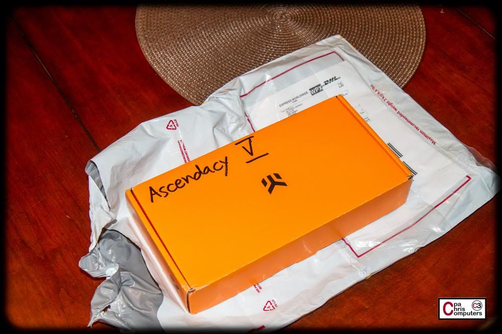
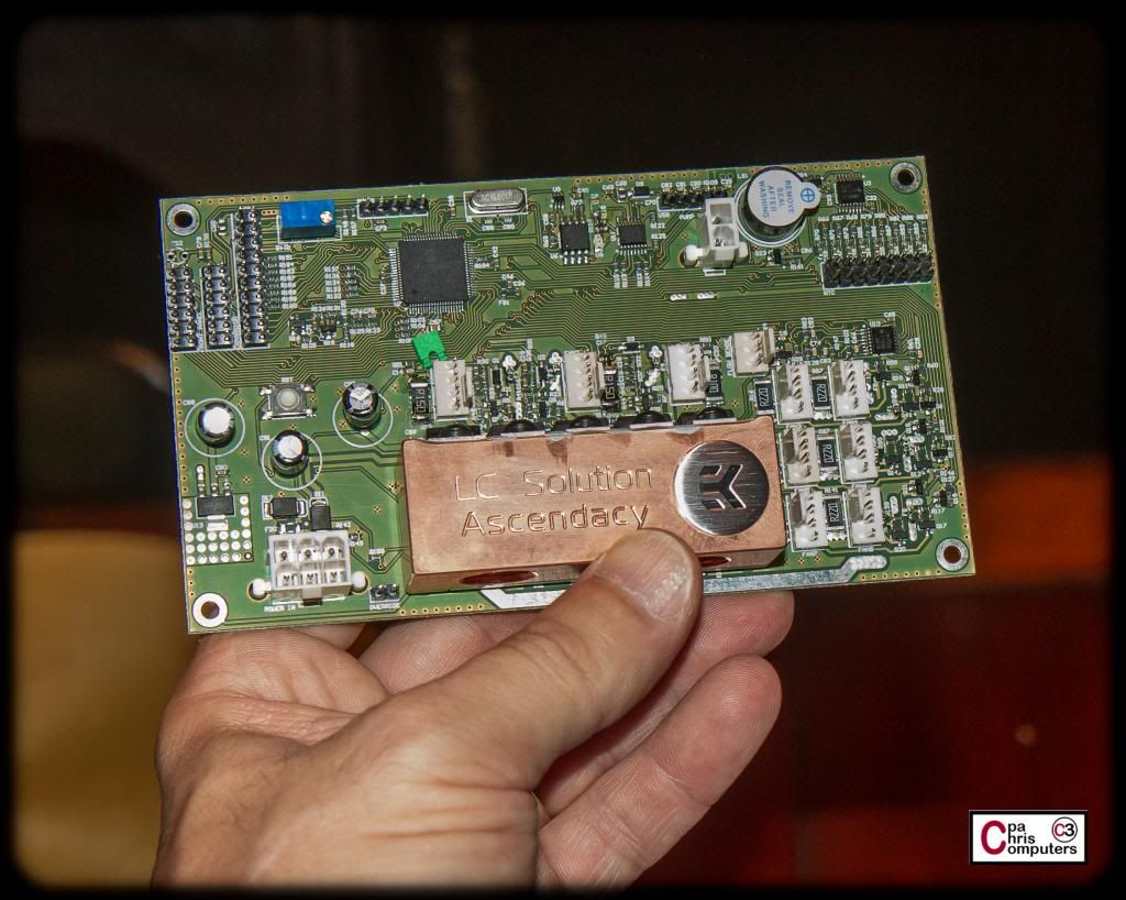
Package from Solvenia! The new EK Ascendacy!!
Sample unit that I'm going to play with and push it to it's limits. Should be fun.....


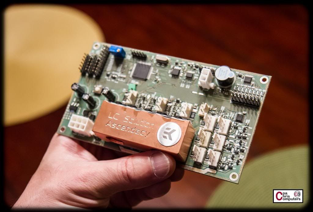
Package from Solvenia! The new EK Ascendacy!!
Sample unit that I'm going to play with and push it to it's limits. Should be fun.....
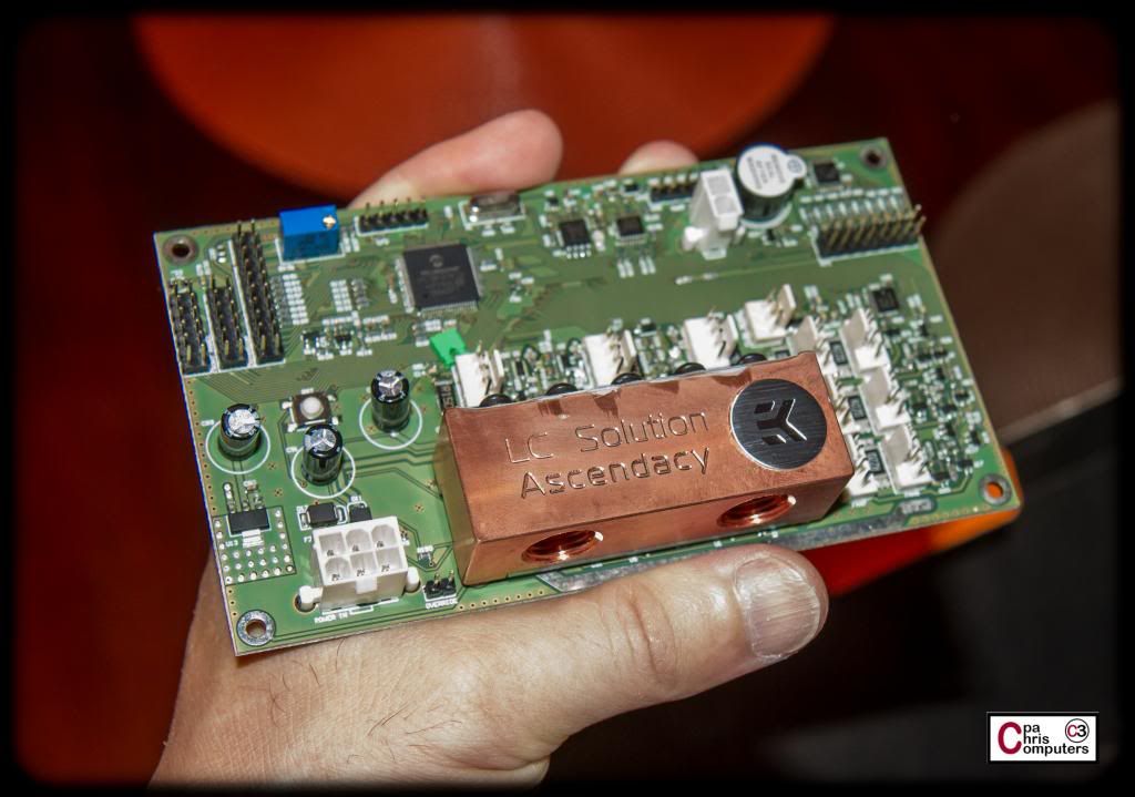
What is that green jumper cap, in the middle of the pcb? Is it stuck in there ?
It was actually just sitting there on the board. Not sure what it will sit on....but I'll report back once I find out.Originally Posted by felix_w

Question: What's more uninteresting than a CPU unboxing and installation?
Answer: Not much. So.....I won't take up toooooo much of your time with these. But here's a few shots. :o
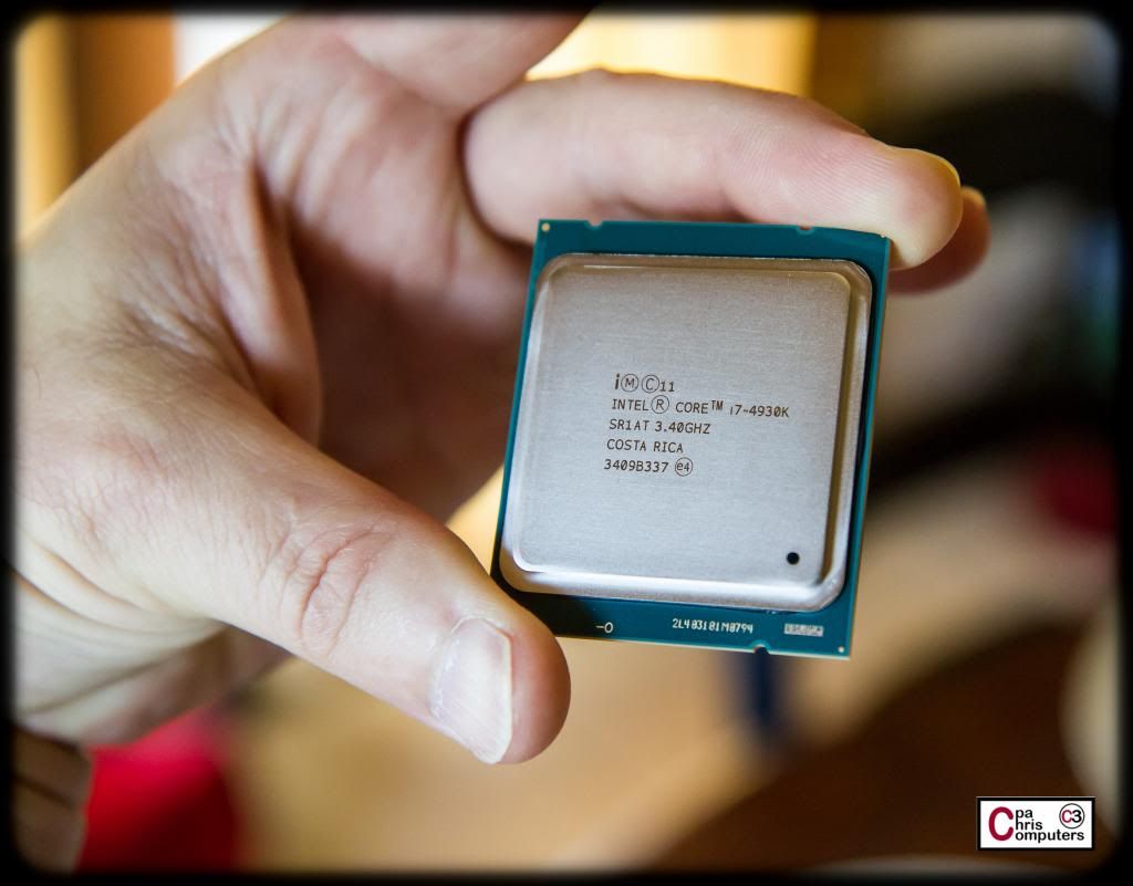
Going with the 4930k for this build.
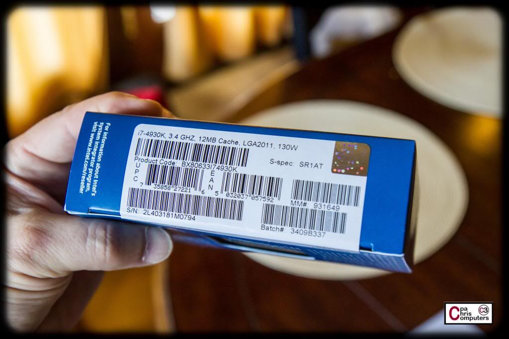
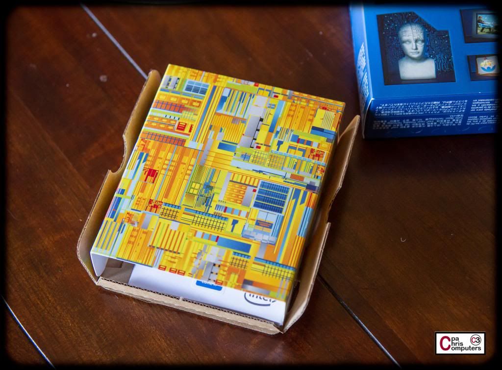
Here are the sticker stats....
I'm not in marketing....but I think someone at Intel should have to explain themselves for the selection of the interior packaging....
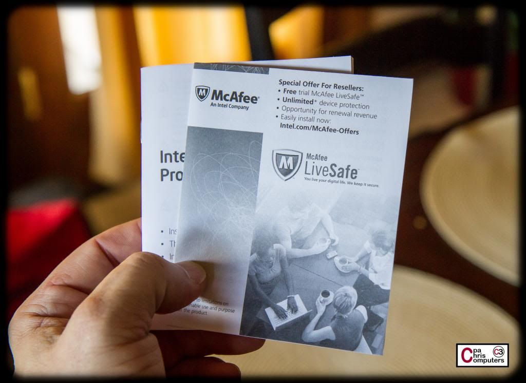
Good news!!!! Inside my Intel box....I got a special offer from McAfee!!!!
Anybody know if this is a good batch for overclocking?
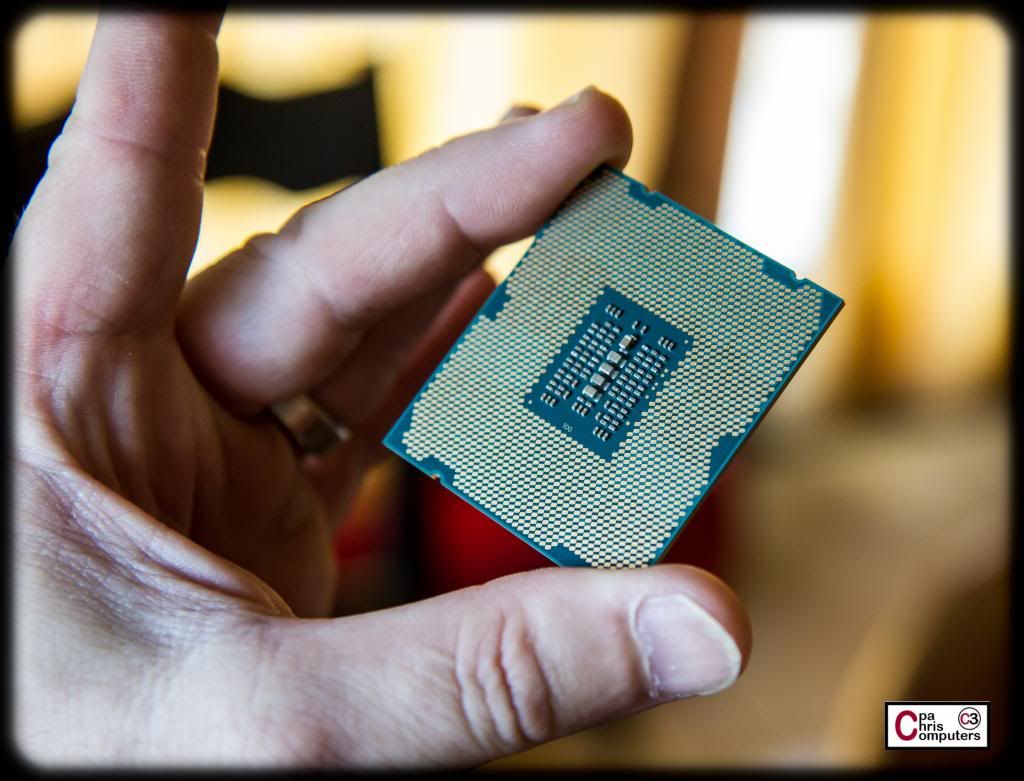
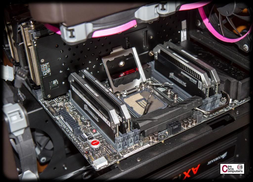
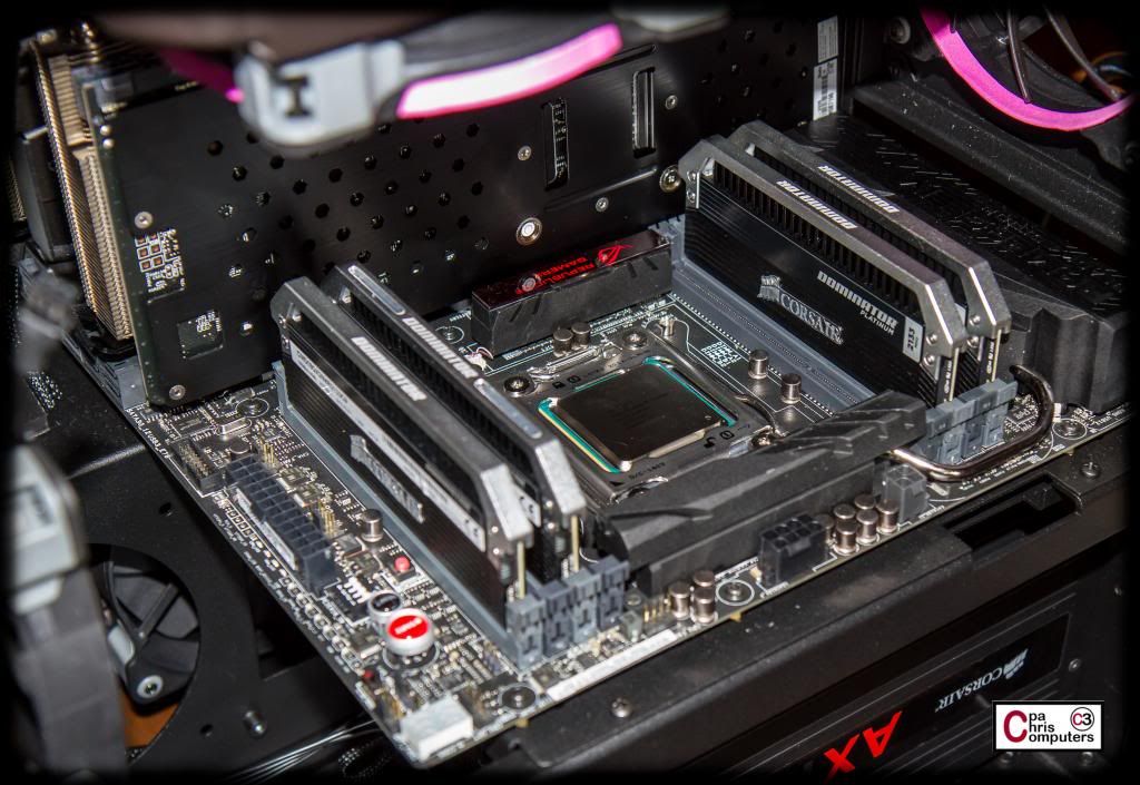
All appears intact. No scratches or other abnormalities......
Pop open the cover.....
...and then put that thing down in its slot. Hard to mess this part up.
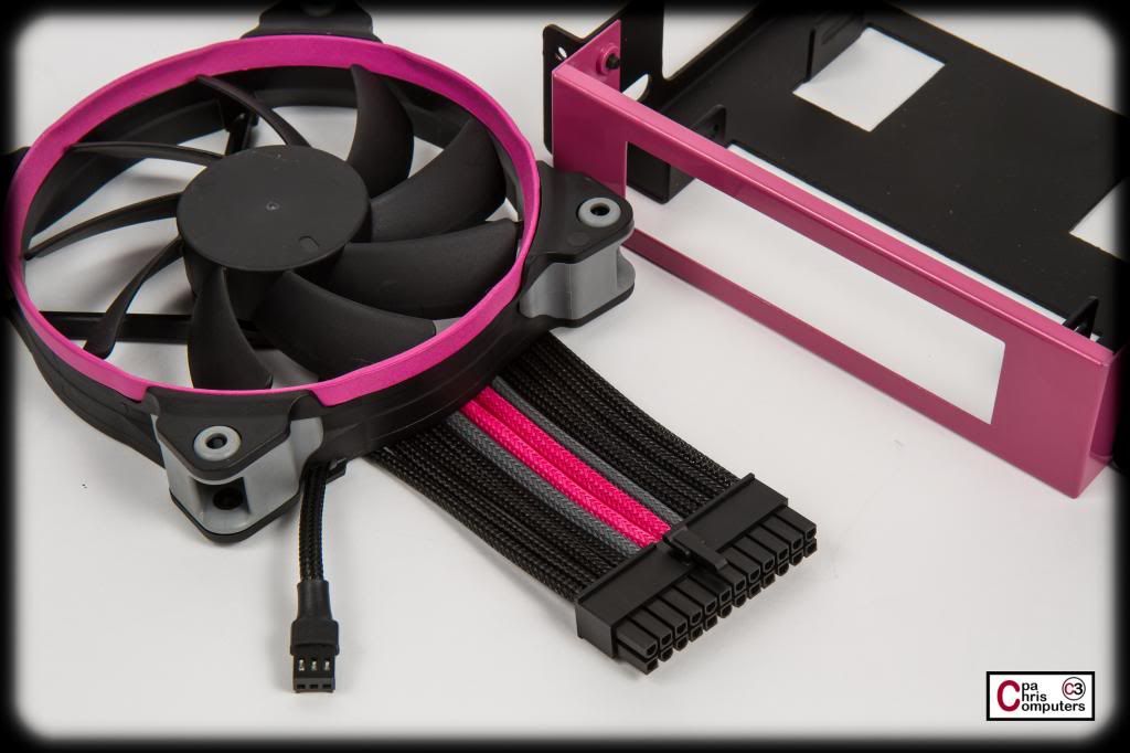
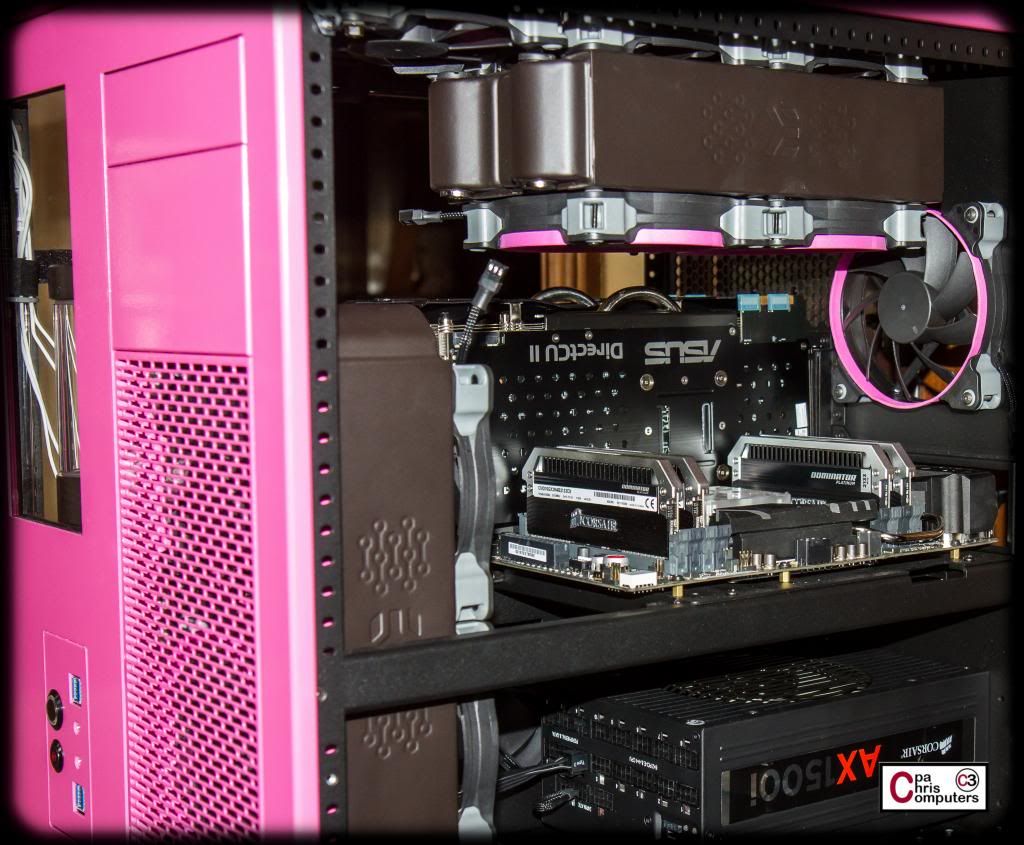
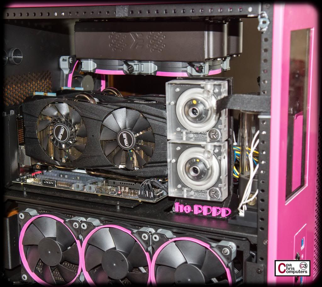
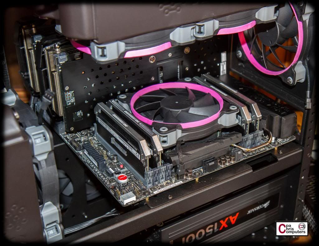
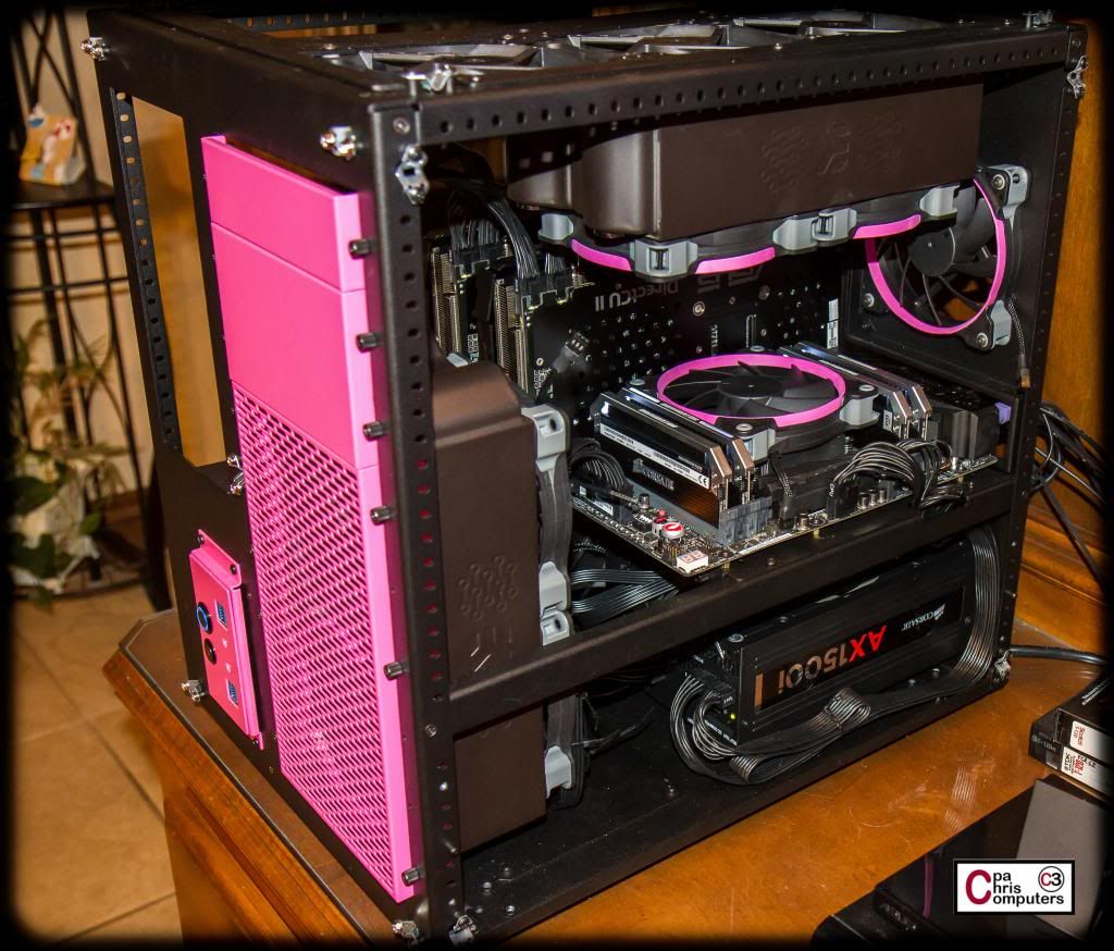
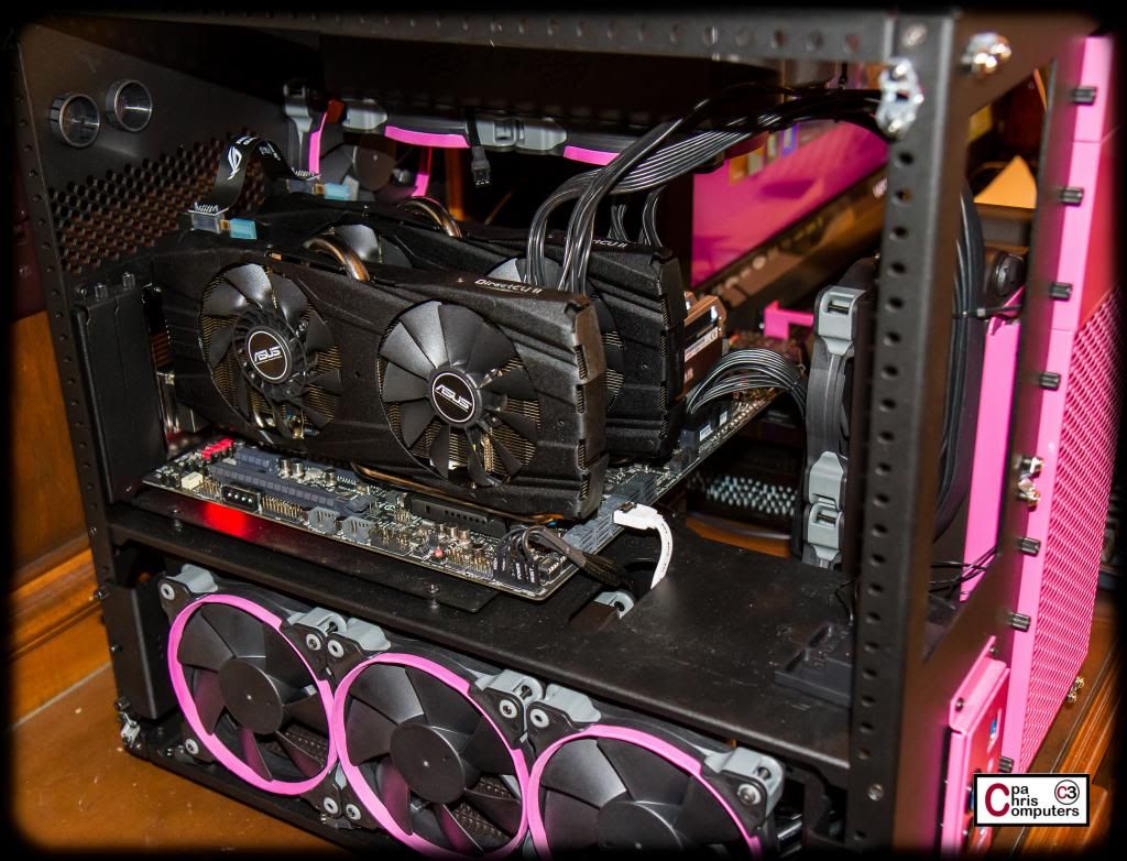
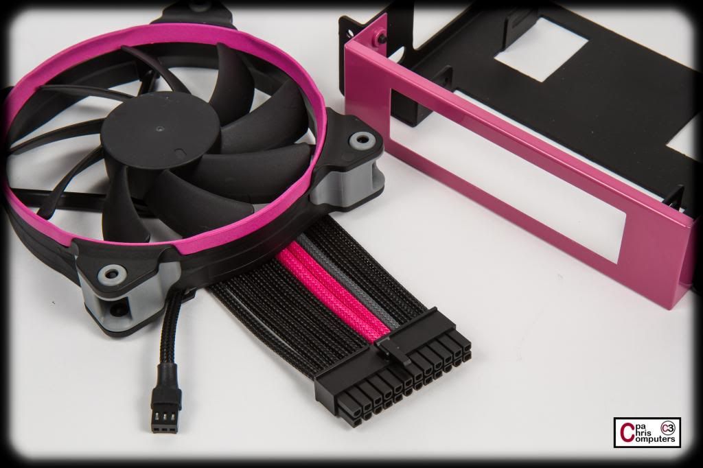
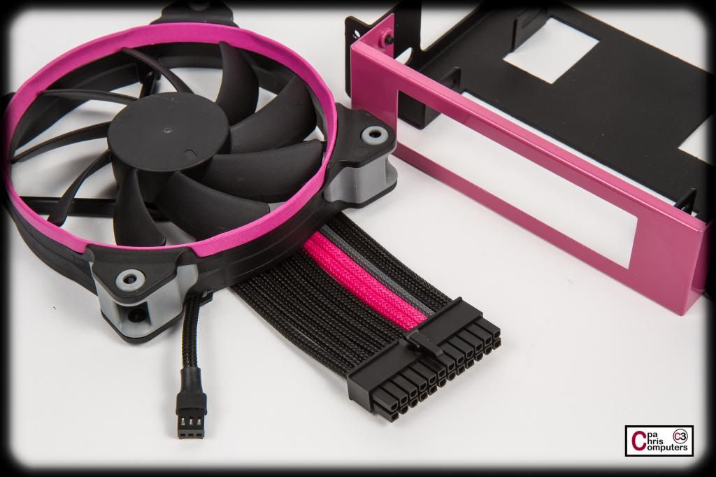
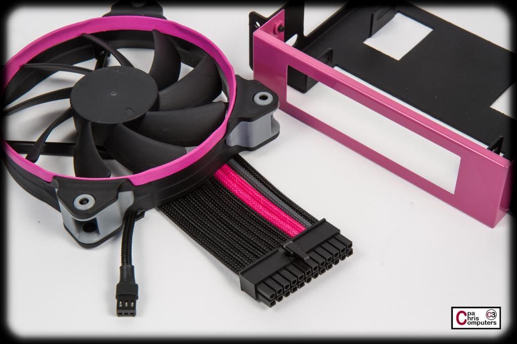
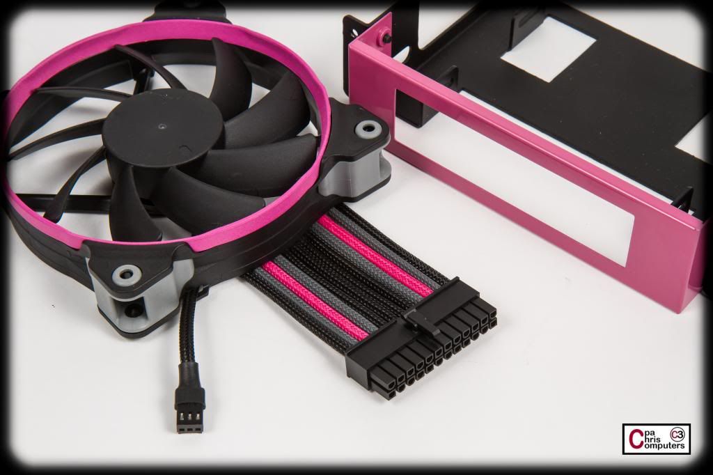
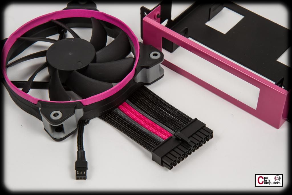
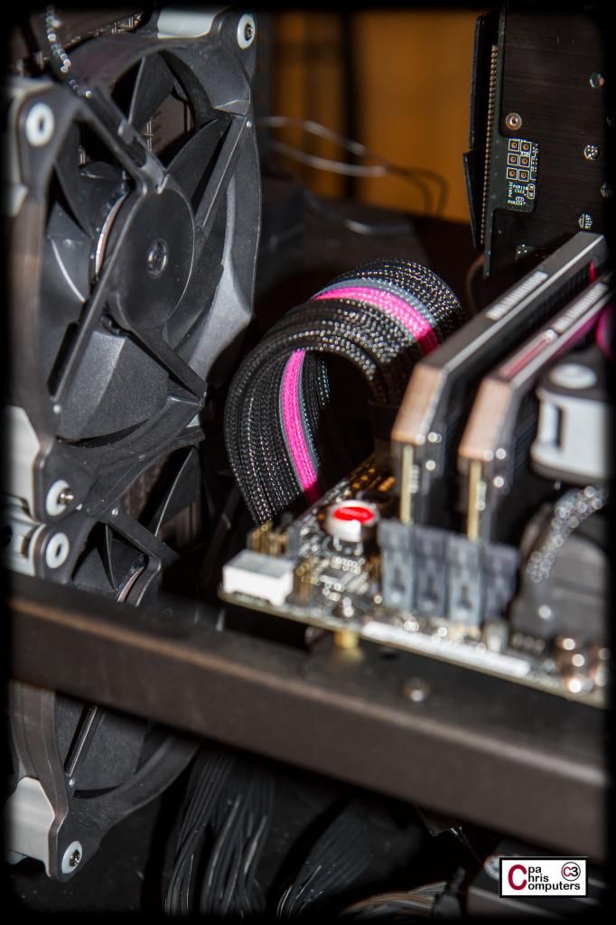
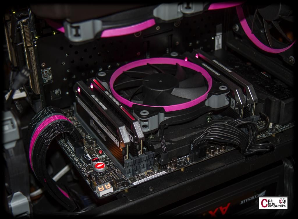
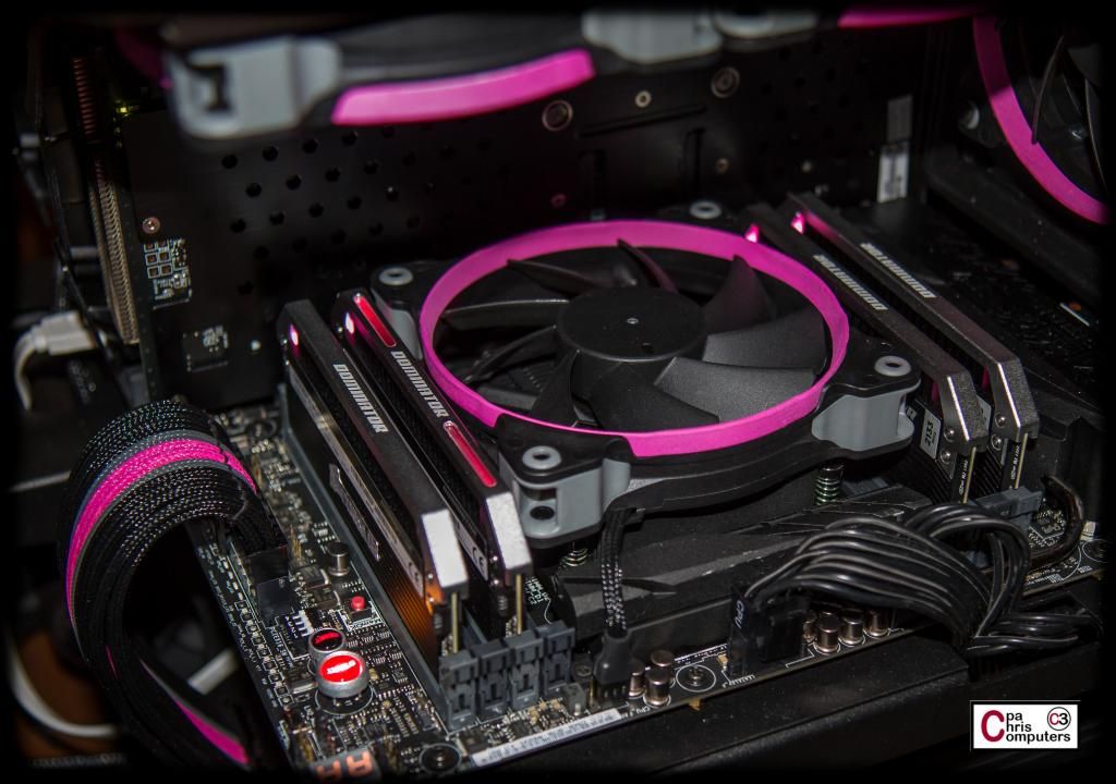
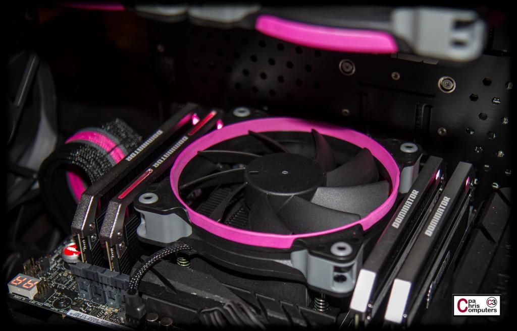
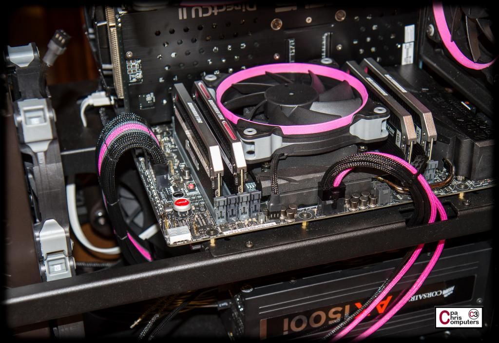
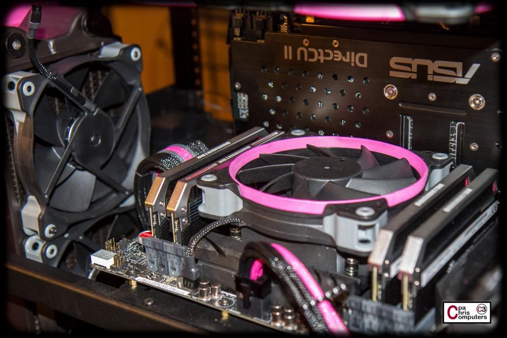
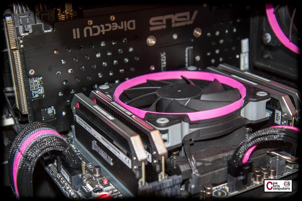
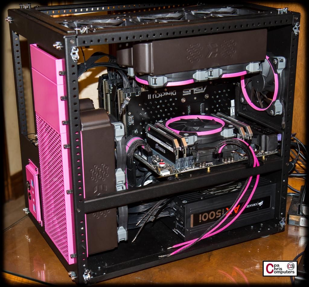
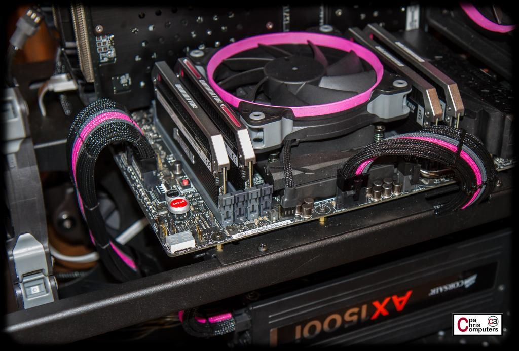
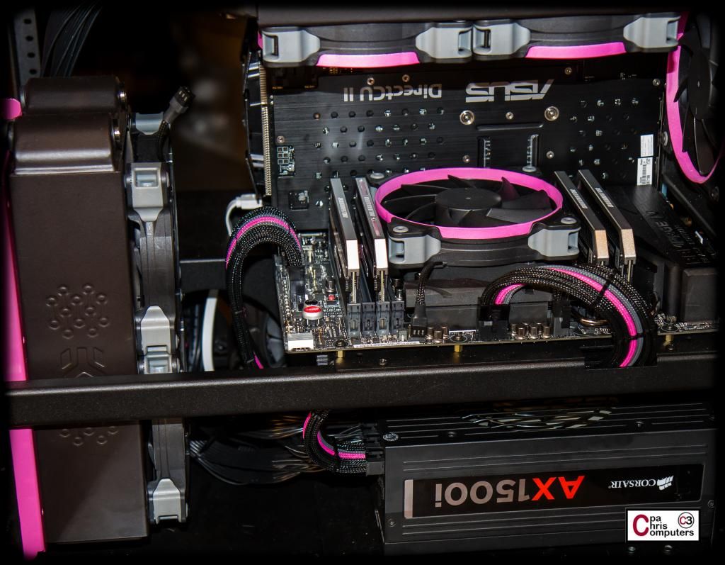
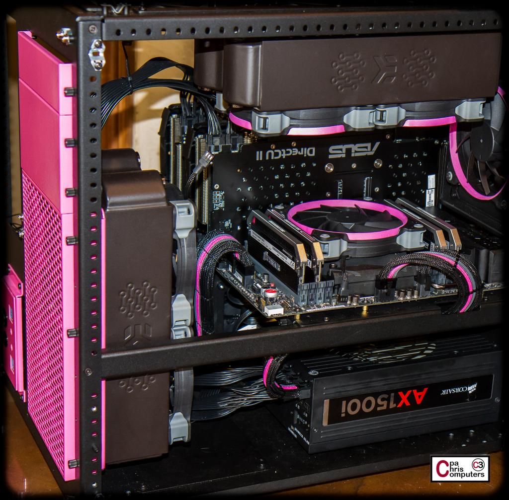
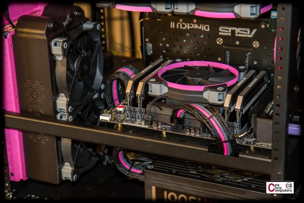
While I've got the case sides off....here a few more shots to show how the fans are looking. Don't have the stickers done yet....but I'm real happy with the pink rings and how they look in the case.
I'll be messing with a temporary air cooler for the CPU this afternoon.....so more pictures later. Need to get this thing booted up on air and make sure everything is in working order.
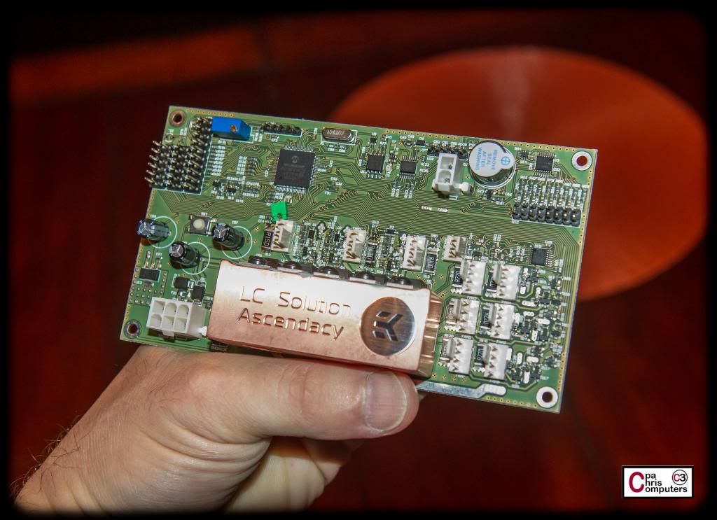
I've re-asked all of the questions that I've received from forum members, and a few of my own, to the EK folks. Here are some more facts that EK has confirmed about the new EK Ascendacy.
1) It's going to be a single 5 1/4 bay unit that mounts horizontally. Interesting.
2) There will be a version that has an LCD screen and the LCD will attach perpendicular to the PCB. Interesting.
3) There will also be a version that does not have an LCD. Kind of like the Aquaero LT.
4) The 2pin PCIe port is intended to power a pump. If you need rpm reporting also, you could run the rpm sensing wire over to one of the PWM ports to the right of the waterblock.
5) Yes, the production units will have a black PCB, and yes the waterblock will most likely be nickel plated.
6) The blue jumper that someone asked about automatically overrides any profiles and feeds all attached devices with 12 volts. I like this option. I like it alot.
7) Much like the Aquaero, the device runs autonomously. Software is only used to make changes to settings and profiles.
8) Overcurrent protection is actively measuring power draw and voltage on the fly. It is not thermal dependent. You can operate the unit without the waterblock hooked up. Just keep TJ-Max below 120 degrees celcius.
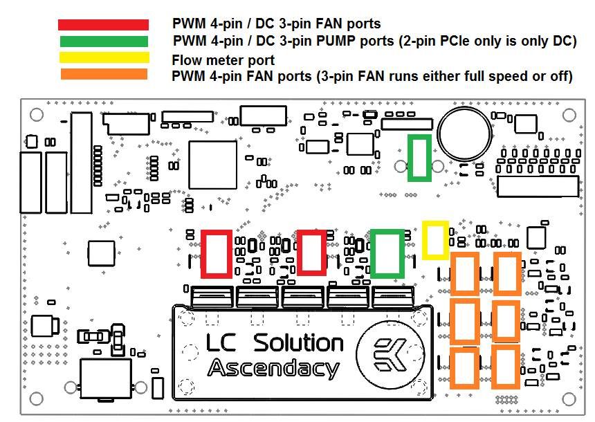
9) This will give you a better idea what the ports do:
The OCP values are subject to change for production units, but right now the Red ports are supposed to be good for about 20W before OCP, the GREEN ports should be good for 40W+. USB connector is right above the 2-pin PCI-e connector.
Hope that helps. Feel free to continue asking questions and I'll accumulate them and forward them on to the kind folks at EK.
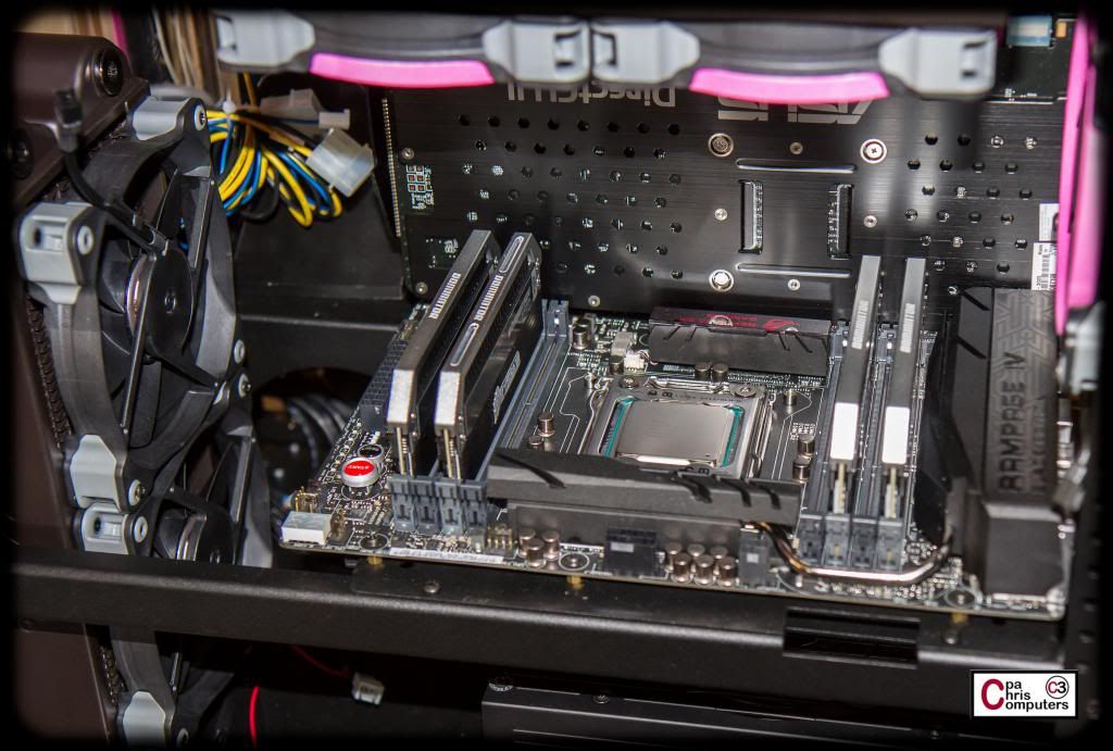
Time for a temporary air CPU cooler so that I can test components and make sure everything is working before moving on to destroying the warranty on everything.
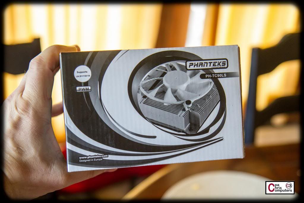
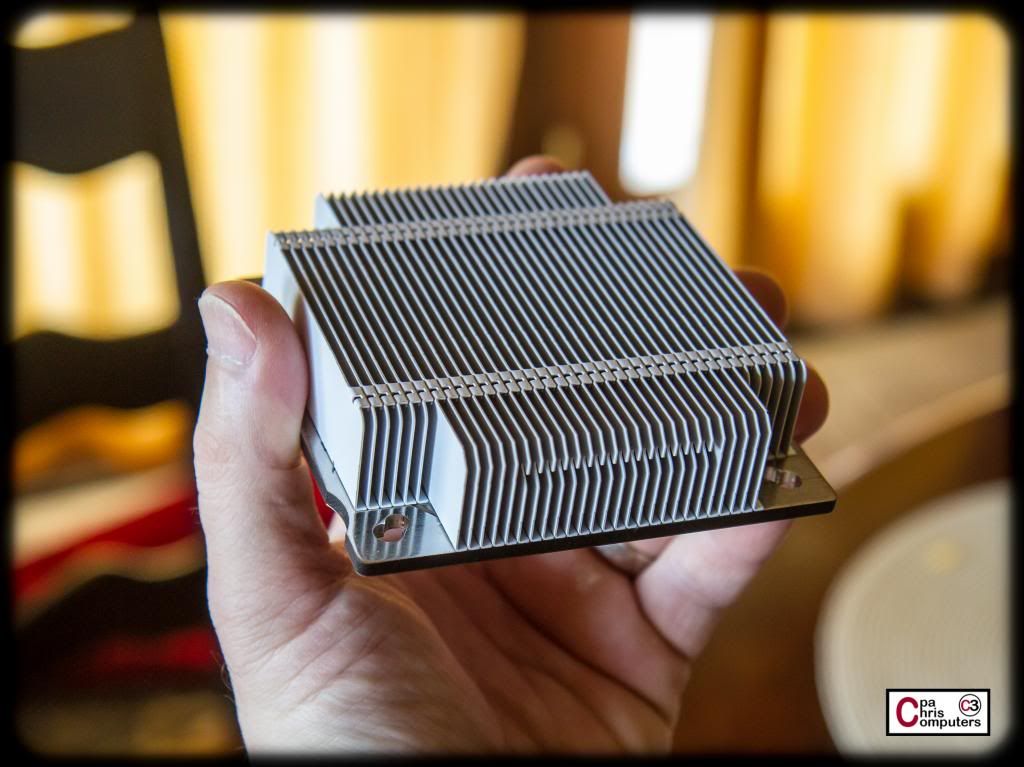
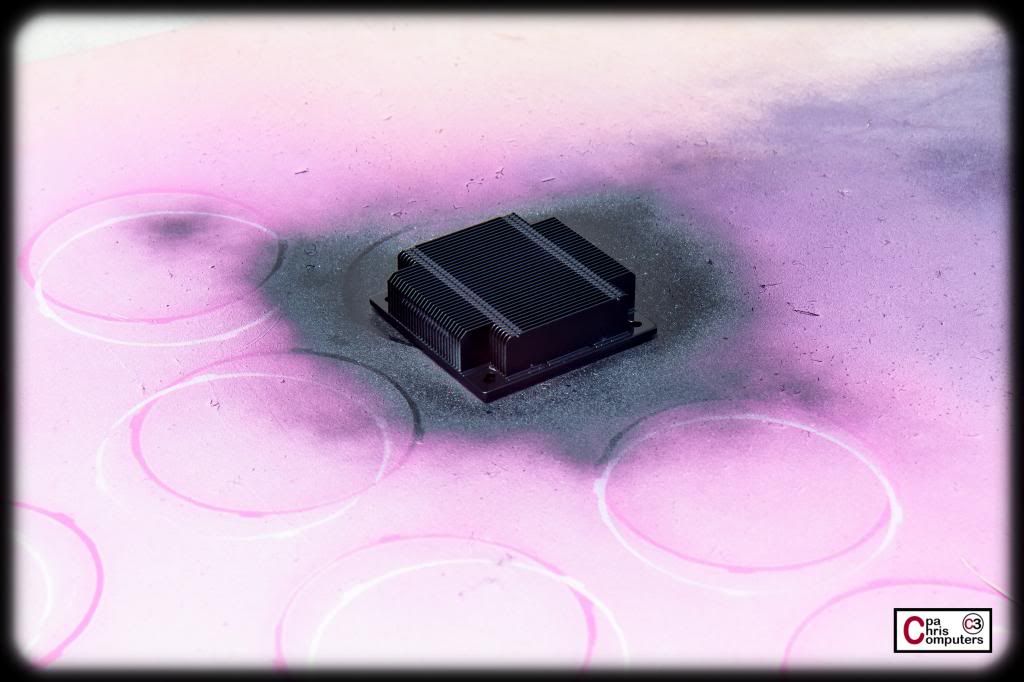
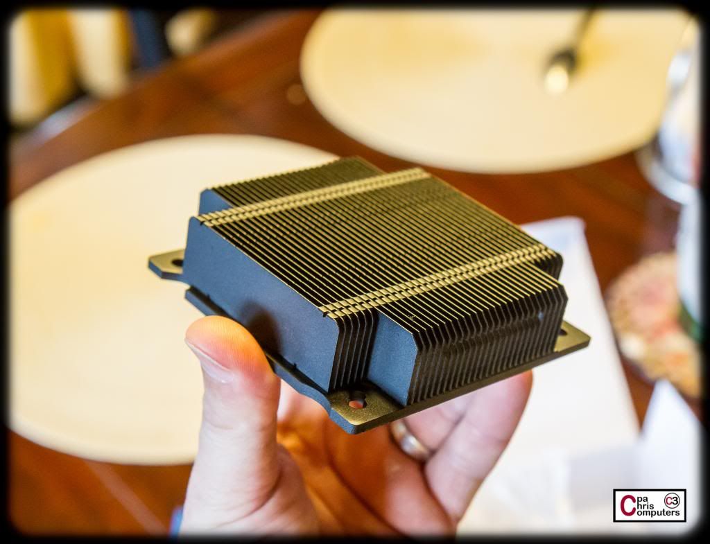
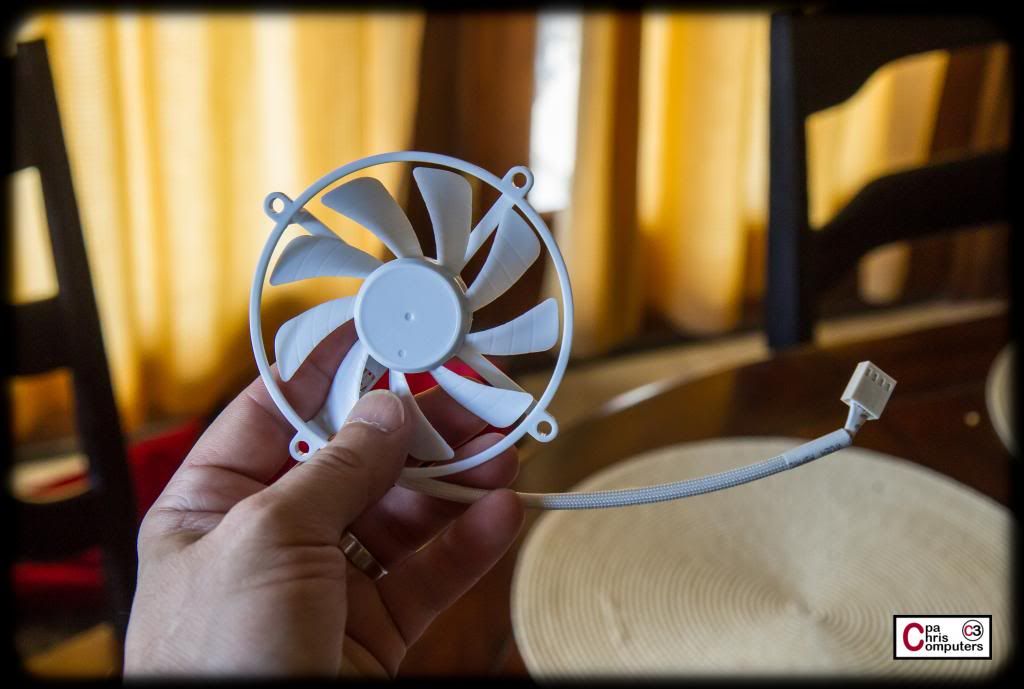
I was worried about space in the S8 for an air cooler since I have that EK radiator right above the motherboard. So I picked up this little bitty CPU cooler from Phanteks....
Hmmmm.....I don't think I knew it was white when I ordered it.
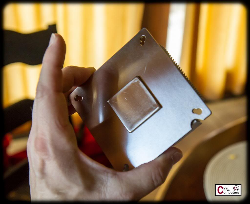
The bottom is not polished all that nicely either....
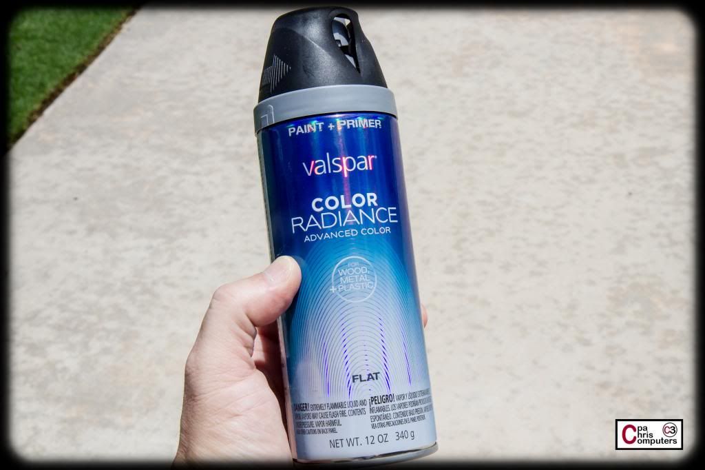
Even though this is only temporary....it would throw off my mojo everytime I looked in the case if I left this thing white. So.....
There. That's better.
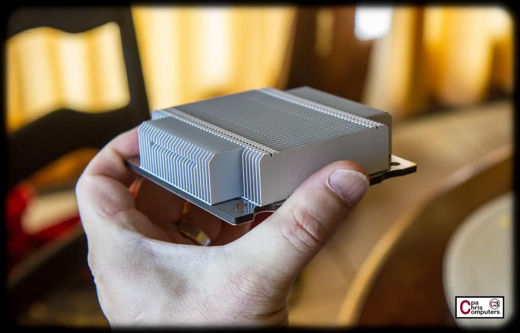
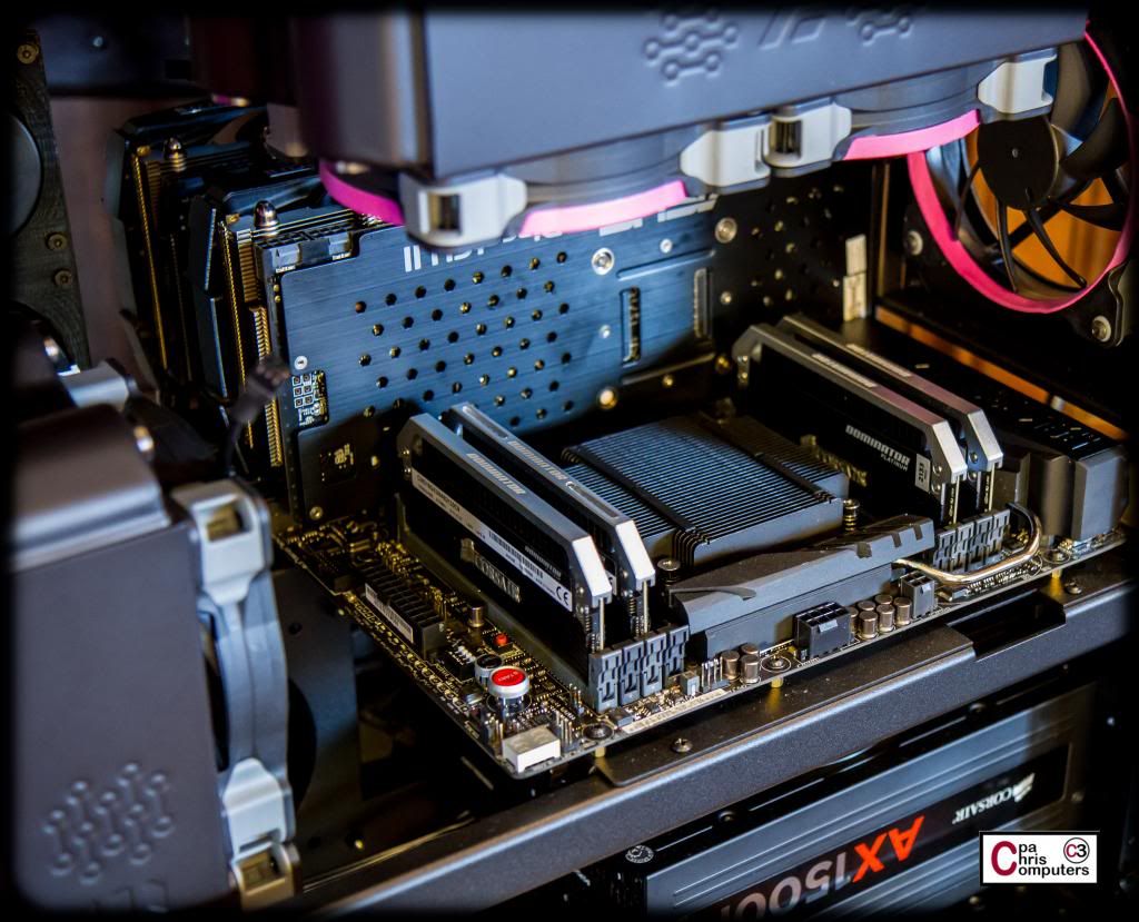
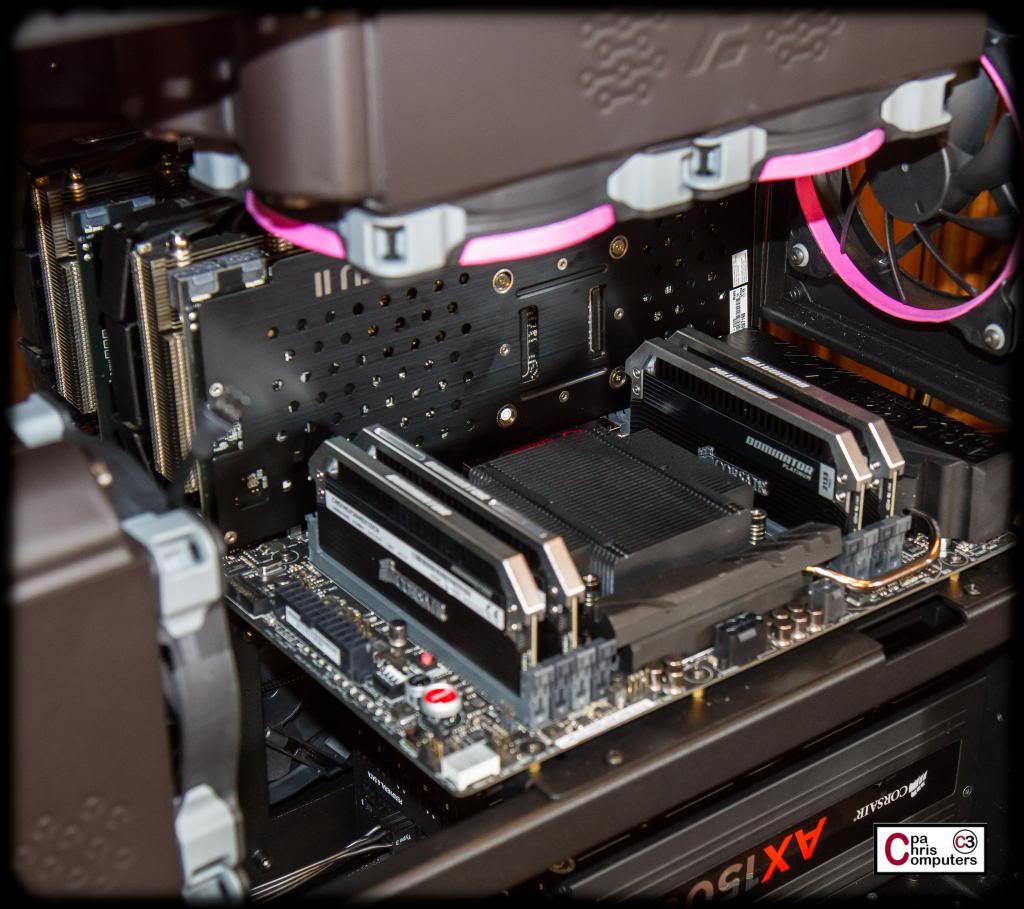
This thing really is small. I don't expect fantastic cooling out of it. But then again, I don't expect to have it in the case for all that long either.....
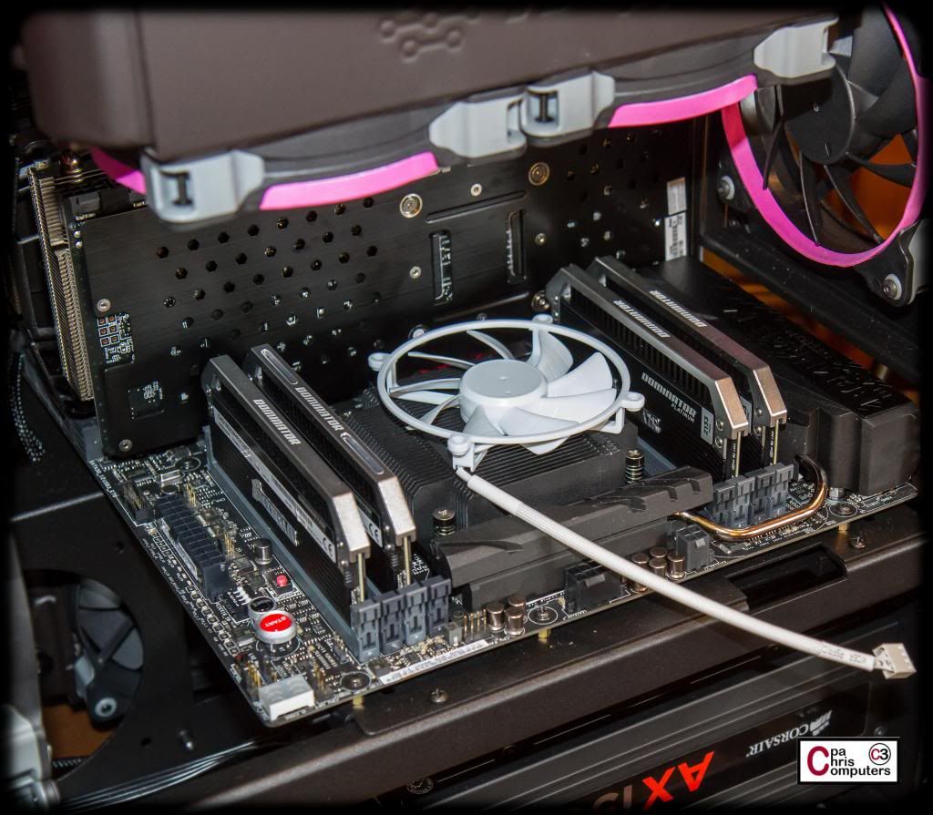
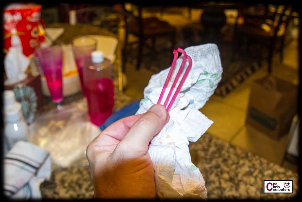
Uh-oh. It also came with a horribly cheap looking white fan. [Pink Floyd Voice] This will not do.
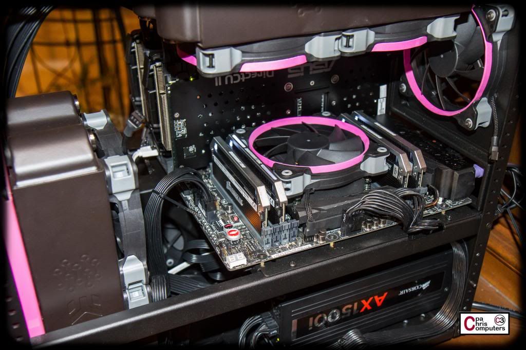
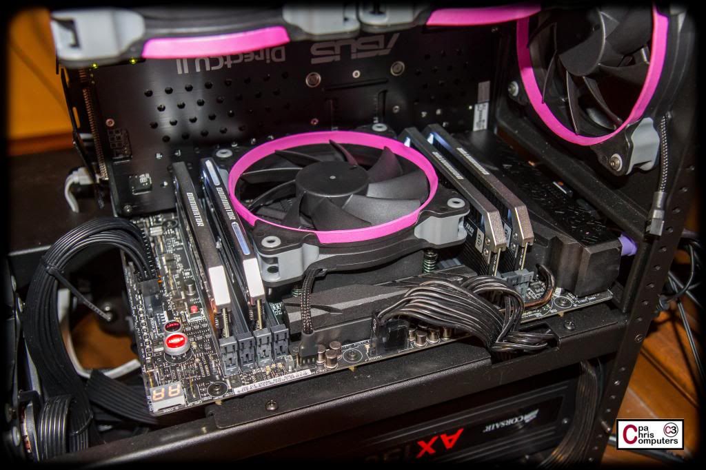
Luckily for me....one of my extra Corsair AF120 fans that has the full pink treatment on it....fits nicely right between the memory sticks.
Aesthetic tragedy averted....time to get this thing booted up.
Last edited by cpachris; 06-09-2014 at 08:54 PM.
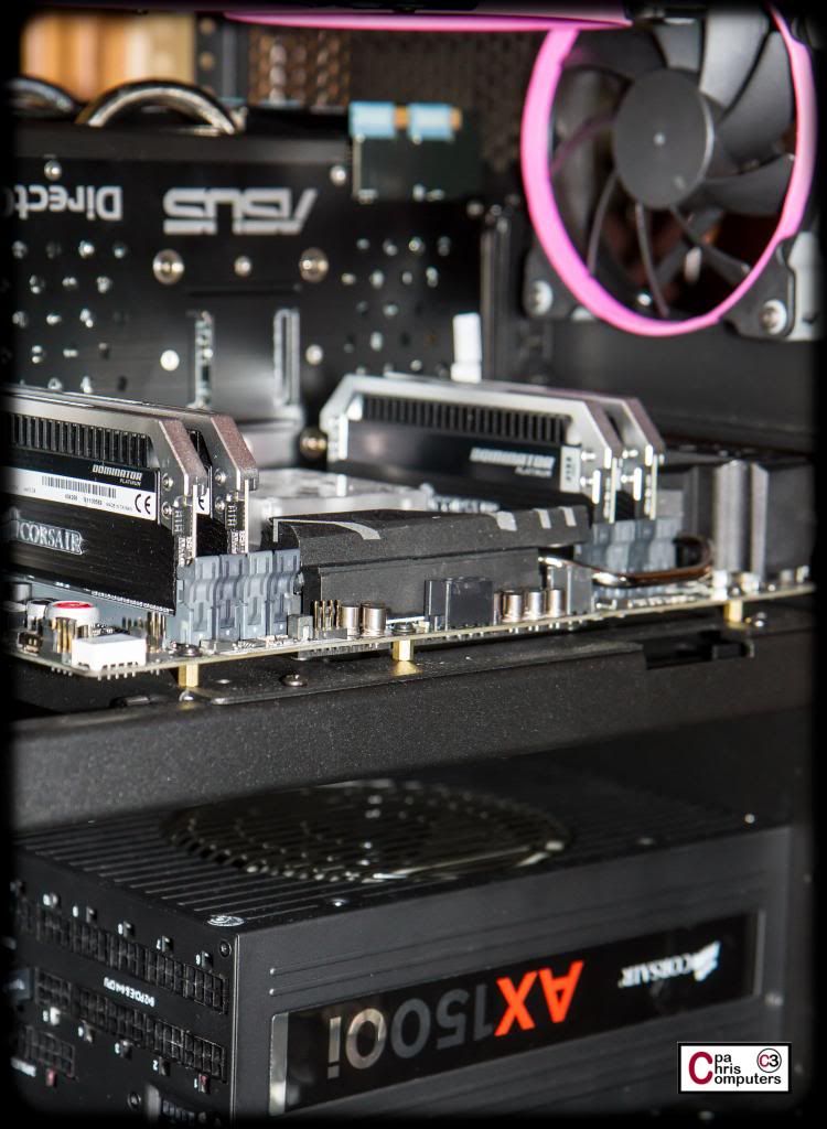
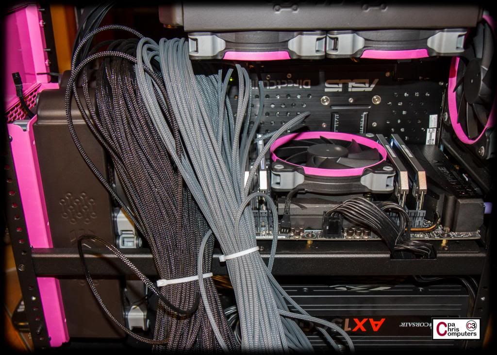
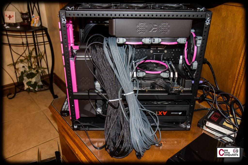
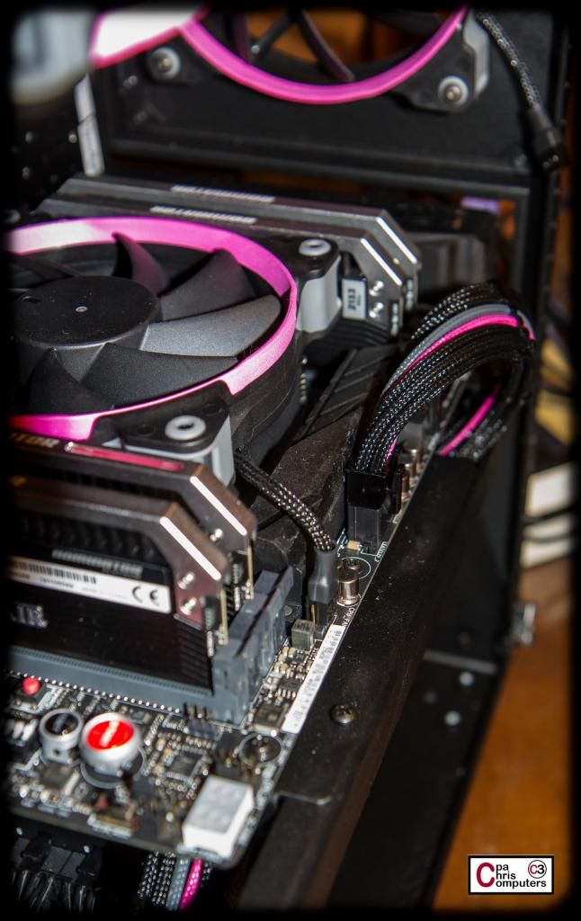
With my quickly rigged temporary CPU air cooler in place, the time has finally come to boot this baby up and make sure everything is in working order. I got out my HUGE bag of cables for my Corsair AX1500i, and started plugging in the required cables. Although the stock cables are clearly not going to be the perfect length for everything I need, the flat black ribbon style cables are actually very nice to work with. I was easily able to fold them over and use zip ties to take up the excess length. Here is what it looked like with the GPU's and motherboard all plugged in......
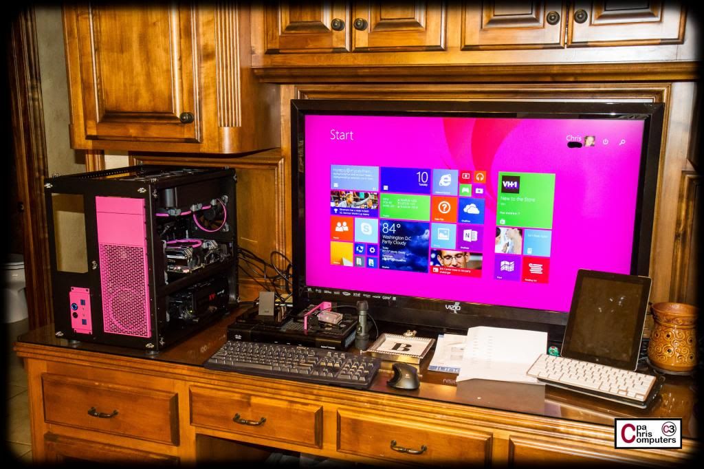
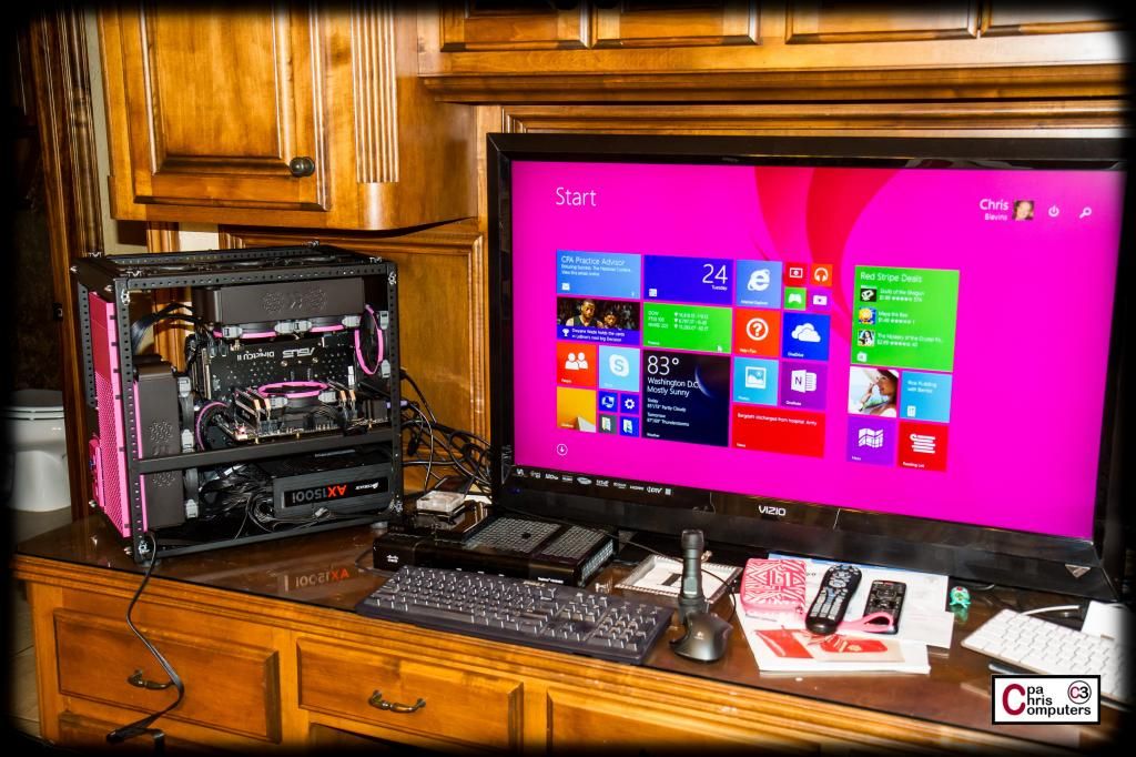
I don't have my 4k monitor from ASUS yet, so I plugged the computer into the TV sitting beside it to use as a monitor. I nervously re-checked all connections one last time, and hit the power button. Success! Nothing to boot to yet, but I got a successful POST and entered the BIOS to start configuring. I plugged in one of my Corsair Neutron SSD's and an ODD with my Windows 8.1 disk, and got that installed. This will be our first 8.1 box in the house. Thought it would be fun to try.
Anyway....the Windows install went REAL fast and problem free. Picture below for proof I'm up and running now...
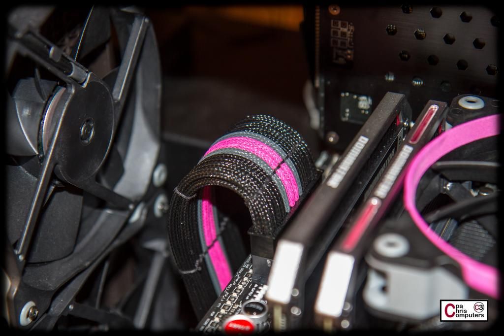
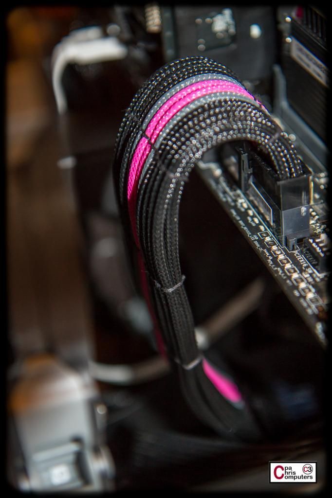
Here are a couple more shots of what the cabling looks like with the stock Corsair cables. I would always sleeve mine...but these really do look nice for stock cables.
Now that I can power up and use the box while I continue to work on it....I'll be able to start playing with that EK Ascendacy I showed a few posts back. Kind of excited to see what it's like.
Next projects on the build will be to get ready all of the remaining parts that will be powdercoated into one last batch. I think it's distracting when you have faceplates and/or mounting brackets, etc., that don't match the build colors, so I'll be getting one last batch of black and one last batch of pink parts powdercoated.
After that, I'll work primarily on custom length sleeved cables while I wait on the powdercoat items to be finished.
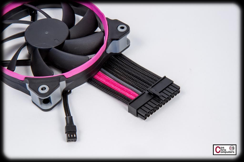
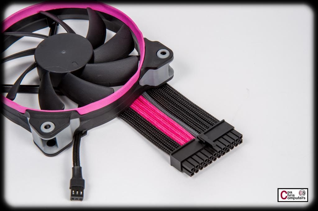
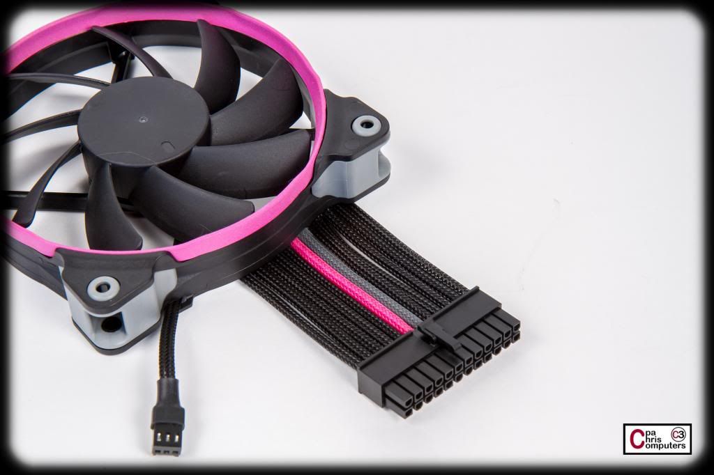
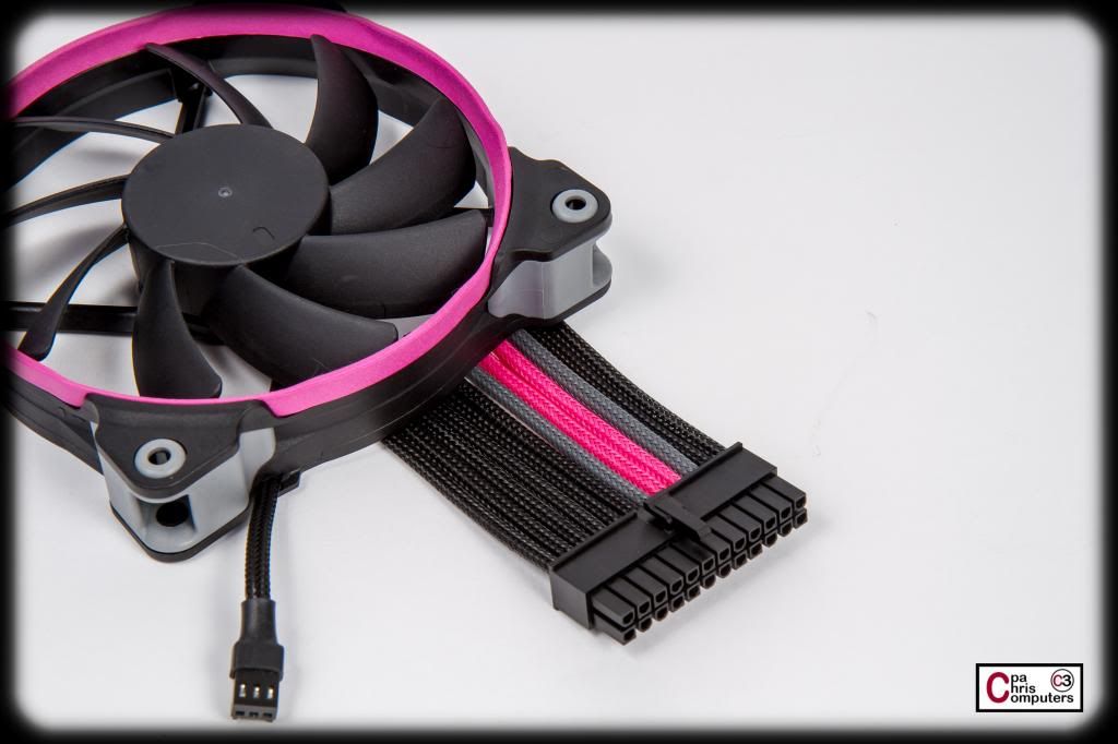
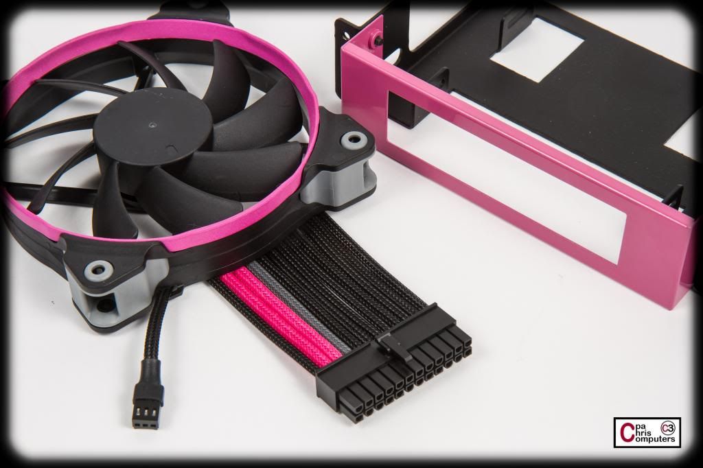
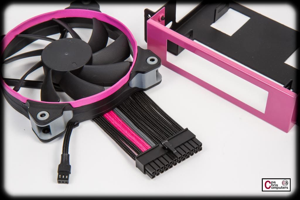
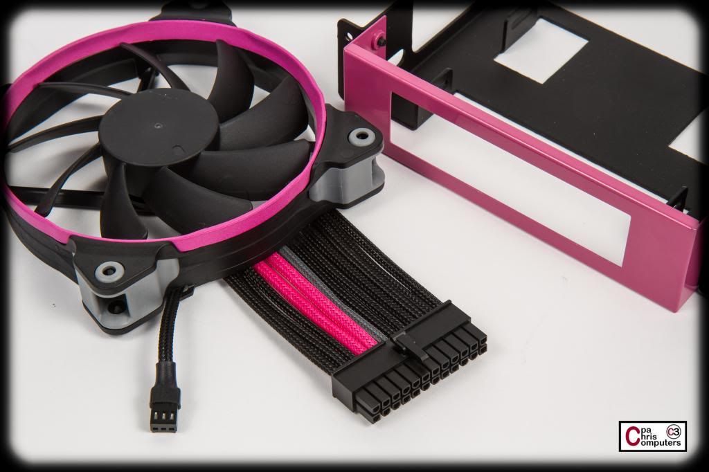
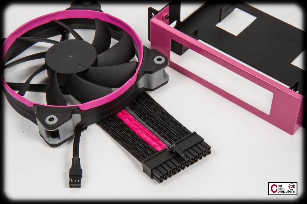
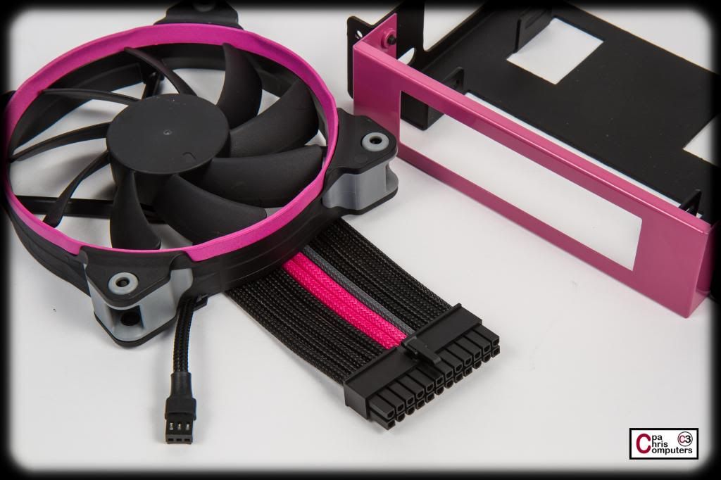
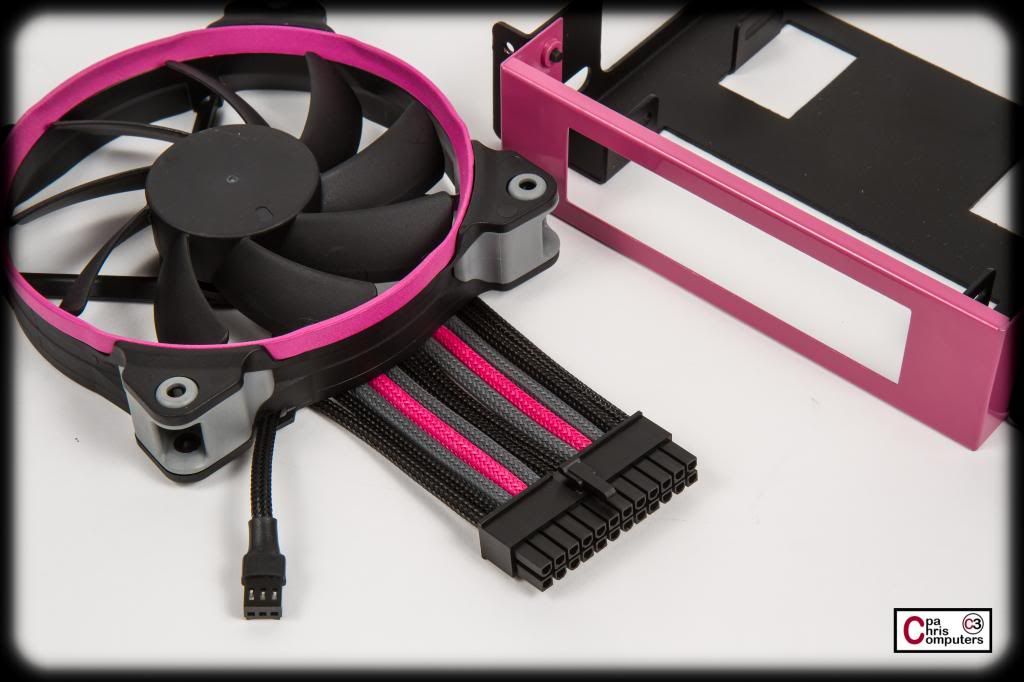
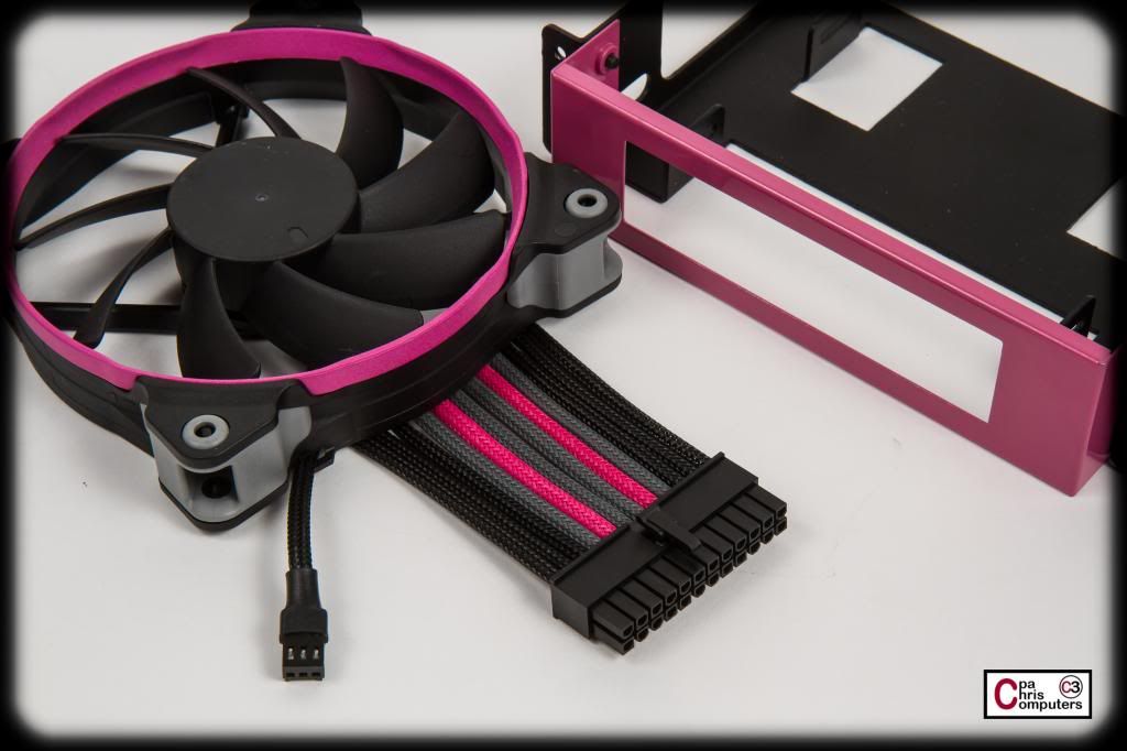
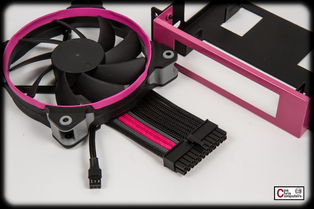
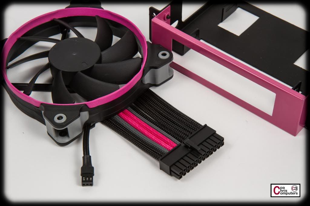
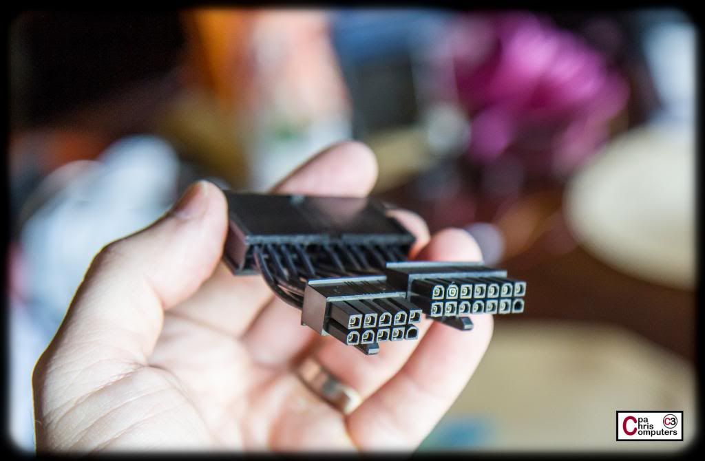
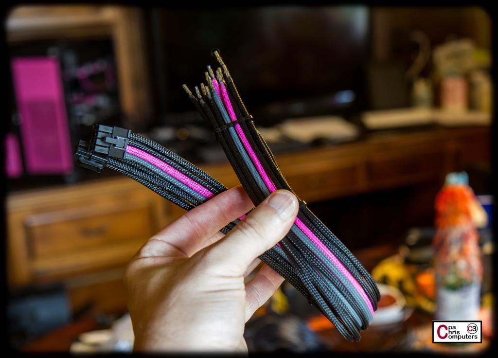
Time to help Jenn pick a color combination for the 24 pin cable....
I want to do a 3 color combination for the PPPP sleeving. Black and pink are the no brainer choices for two of those colors. I think we'll use grey for the 3rd color.
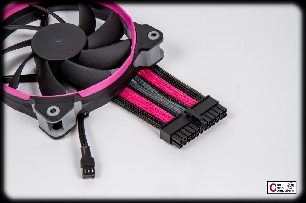
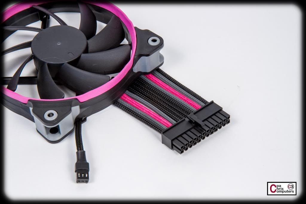
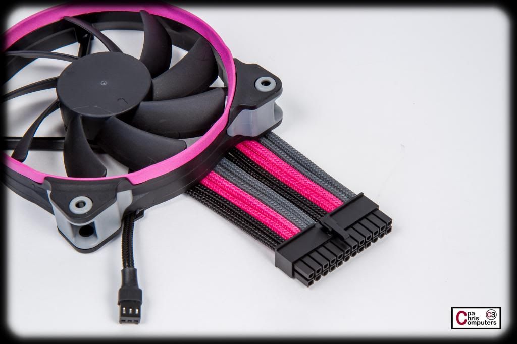
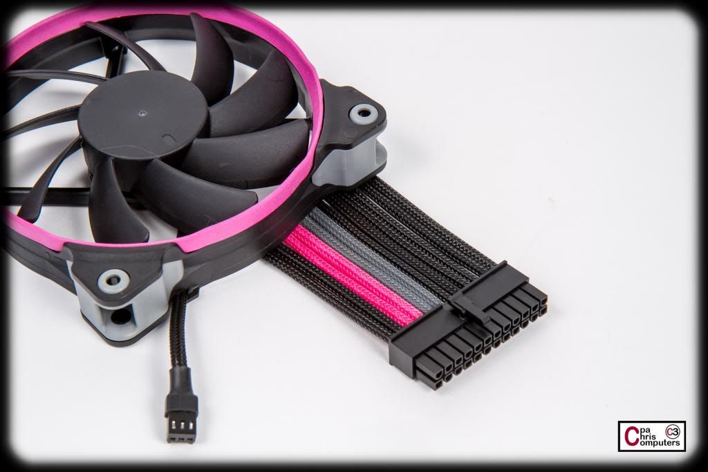
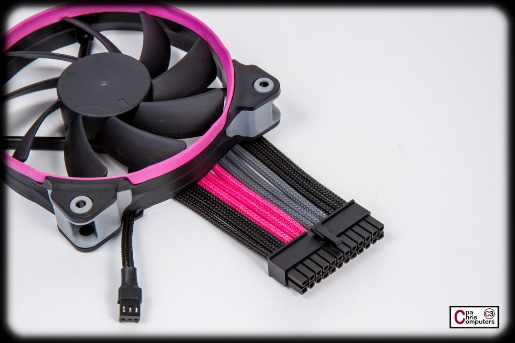
These shots are just to show the black and grey Telios sleeving from Lutro0 Customs, and how it fits with the color scheme of the ASUS RIVE BE and The Corsair fans. The RIVE BE has both black and grey ports for several things. One set of the memory slots is black, and one set is grey. They also use black/grey to differentiate their SATA2 and SATA3 ports. For the Corsair fans, they all have the grey rubber vibration dampners on each corner....so there is also plenty of black and grey for the fans. Grey just makes sense for the 3rd color....
So I used some of my test batch of pink dyed Telios, along with some black and grey, and stuck them in a 24 pin connector for some combinations. From left to right we have....
#1 - BBPPGBBBBBBB
#2 - BBPPBGGBPPBB
#3 - BGPGBBBBGPGB
#4 - BBPPGGBBPPGG
#5 - BBPPGBBBBBBB
#6 - BBBPPPGGGBBB
#7 - BBBPPPGBBBBB
#8 - BBBBBPGBBBBB
#9 - BBBBBBGPPGBB
Jenn gets to decide what she wants....but I'll tell you now that she was heavily influenced by forum opinion in selecting the fan combination colors. So....here is your chance to influence her. Let her know what you think would look best in her pretty little pink computer! Or feel free to suggest other options. Like they told me in Louisiana.....vote early, and vote often!
Ok. I've summarized all of the preferences/favorites/votes from all of the forums where this build log is being replicated....and here are the results from forum members.
The top 3 vote getters ended up being #1, #3 and #9:
#1:
#2:
#3:
There was a group of 4 options that all received significant support, but not near as much as the top 3 vote getters. These were #2, #4, #5 and #14.
Before I let Jenn absorb all the forum wisdom, I sat her down in front of Lightroom and had her start picking favorites and explaining to me what she liked and didn't like about each one.
Her 4 favorites were #1, #3, #7 and #9. So three of them were identical to the top vote getters among the forums, with only #7 being the one that didn't receive a lot of forum support.
#7:
TBH....I think #7 grabbed her attention because it was a lot like #1....but more centered. She liked the thinner pink stripe (2 pinks in #1) more than the thicker pink strip (3 pinks in #7), so I think she might really like a variation of #1 that was more centered. She seemed to want the overall look to be predominantly black....and veto'ed some of the ones I thought were pretty, just because they had "too much color". She also seemed to really like it when the grey sleeve was a border around the pink. My baby knows what she likes.
So....based on what I think I know now...I'm going to present her (and you all) a final group of pictures to select/vote from. They will all be based on either #1, #3 or #9. For the #1 variations....I'll play with different locations for the PPG stripe to sit. The #3 variations will all be double stripes, and I can have 2 or 3 different places for the double stripes to sit....and they don't necessarily have to be symmetrical. For the #9 variations....I'll play with different locations for the stripe, as well as both single and double pink variations.
I should have those picks posted later today or tomorrow......
Can't wait to get started!

why the grey? i would personally like alot of black, a little pink, no grey.
if grey, border the pink with it.
I've always like 3 color combinations better than 2. And...the grey just matches the Corsair fan corners so well.....
I'd go for #3...
Picking up where I left off........
We/I/Jenn had narrowed down the initial list to 3 favorites. For each of these 3 favorites...I can spin it several ways.
First up....are Group #1. Group #1 all has a PinkPinkGrey combination inside the black cable. Different spots to put the PPG. We could do:
1-1
1-2
1-3
1-4
1-5
1-6
1-7
1-8
I know she wants black on the outside edges of the cable...so those are the possible combinations.
For Group #2, there were double stripes. Jenn called them racing stripes.Each stripe was a GPG combination. We could put these at a few spots in the cable, including:
2-1
2-2
2-3
For Group #3, we had the single stripe, but it was in a double pink GPPG combination. We could put these in the following locations:
3-1
3-2
3-3
3-4
As a next step Jenn is going to pick her favorite from each group, and then narrow it down to the final one. She'll probably be weighing in with her selections tomorrow....so feel free to try and influence her along the way....
Jenn has narrowed it down to 4 options, and is going to sleep on it one more night before making a final selection. Thank you to everyone who has influenced or steered her in the right direction.
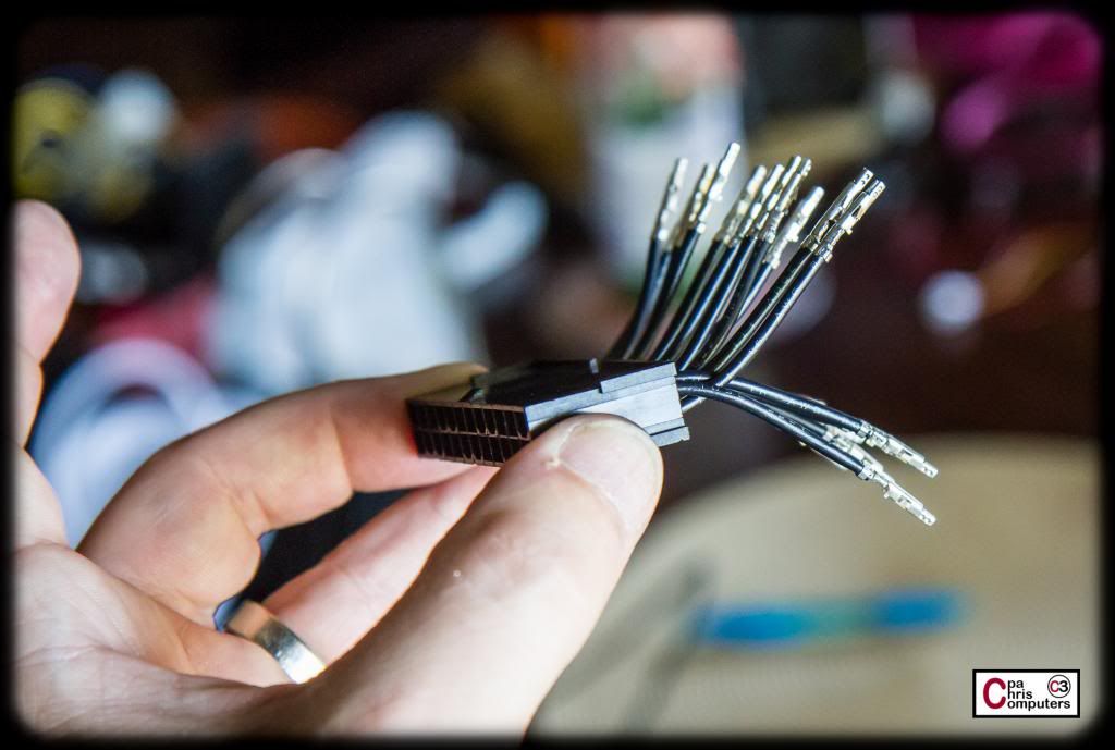
Today's project involved getting ready for making that 24 pin cable. The Corsair AX1500i is close to a 1 to 1 pinout for the 24 pin....depending on how your board and PSU are oriented. There is, however, 1 double wire on the motherboard side, and one empty hole on the motherboard side. Close....but no cigar. The other thing I was noticing as I traced the wires from the PSU to the motherboard, is that I was going to need to flip them. If you picture an nicely done extension in the shape of a 1/2 circle....the wires on the inside of the C stay on the inside of the C for the whole extension. Wires on the outside of the C stay on the outside of the C for the whole extension. If I was going to run cable straight from the PSU to the motherboard, I would have to deal with the situation of the inside of my "C" at the PSU connector, would have to become the outside of my "C" at the motherboard connector. This can ruin the look of a nice and neat 24 pin. Combine it with the double wire I have to deal with, and the 24 pin could get messy....
The way I handled this on the BBBB, was to make a short power cord that handled all the non 1 to 1 and double wire connections. It had female connectors on the PSU side using the PSU specific connectors.....and had a male connector on the other end....that could be plugged into a typical extension. This allows the extension to be 1 to 1 and perfect....while the short cable handles all the messy stuff. I'm going to do something similar here for the PPPP.
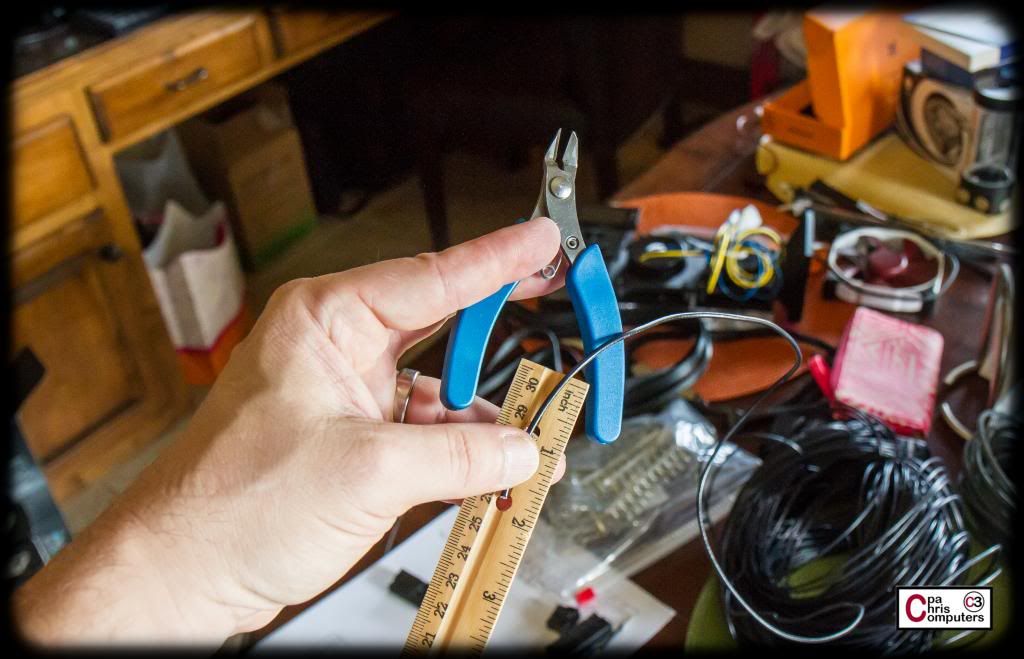
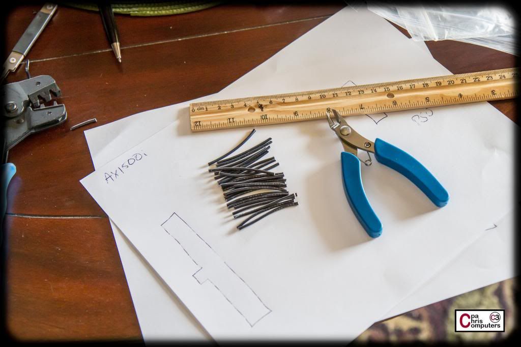
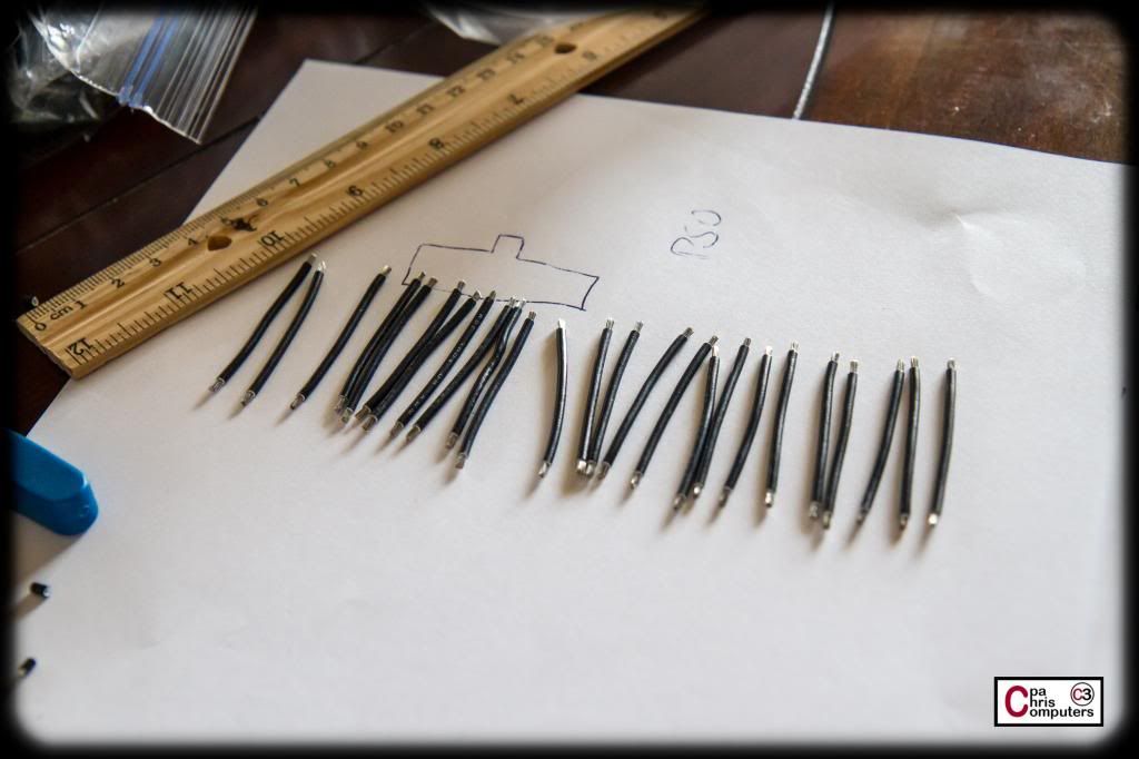
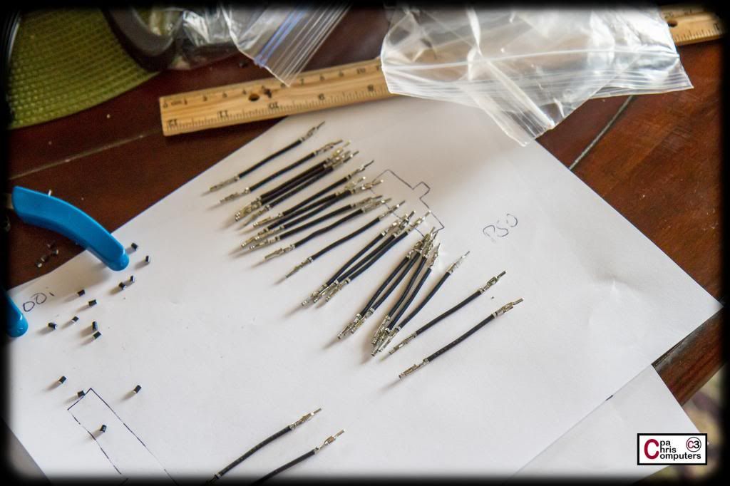
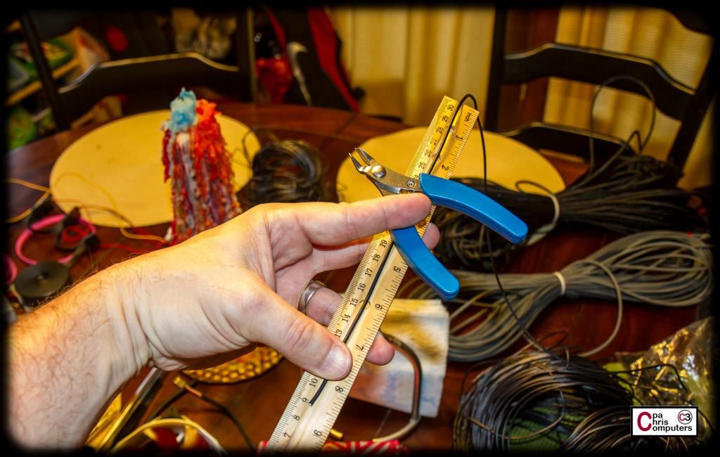
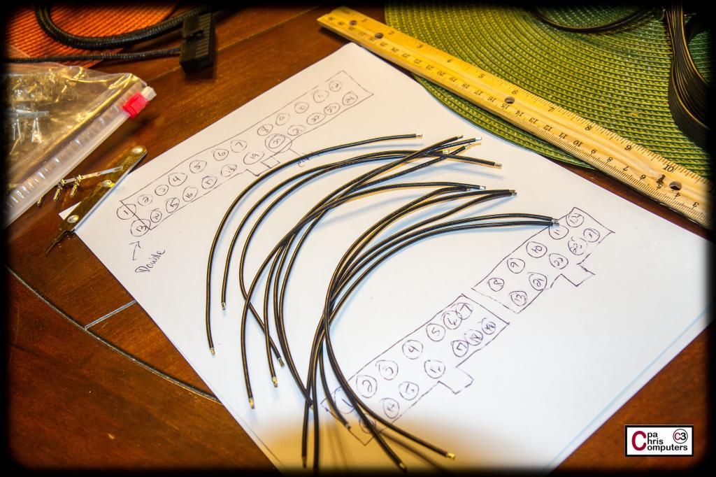
First step was to cut some lengths of wire for this short power cable. I'm using my Lutro0 special 16 AWG wire. Through a couple of practice runs, I ended up settling on 1.75 inches for the length of the wire for the short cable. Too long....and it looks messy. Too short...and I wouldn't be able to have enough slack in the wire to make the connections. Was using the Lutro0 snips for this step also. They work really well for cutting wire. I don't think they work as well for cutting sleeving.
You already know I like assembly line style work....so I cut all of them I thought I would need...plus a few more. For mistakes....
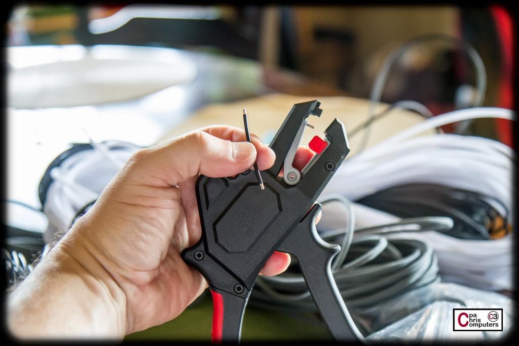
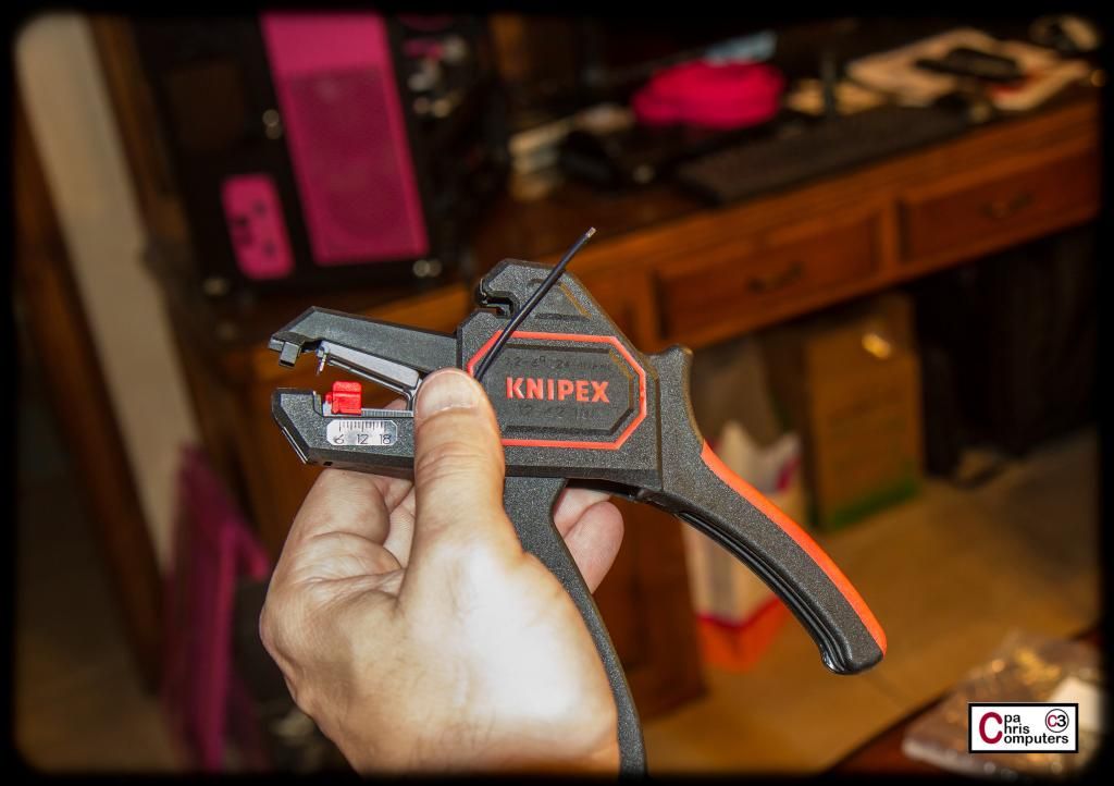
Next I got out the Knipex wire strippers (also from Lutro0) and took off the perfect amount of insulation on everyone of my lil' pieces of wire.
Look at those brave lil' soldiers....
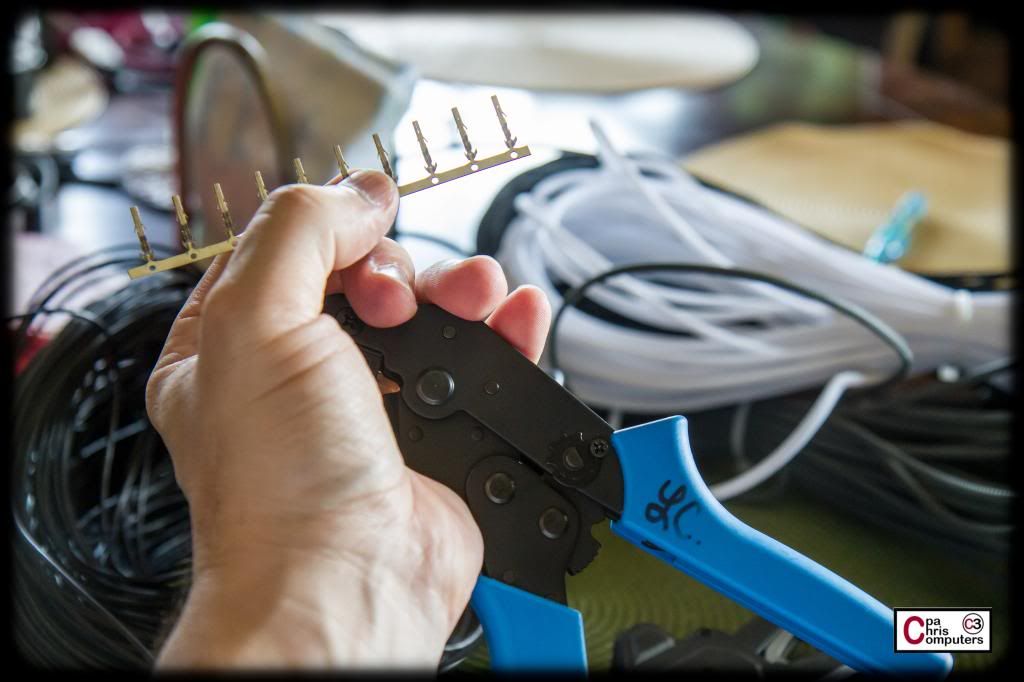
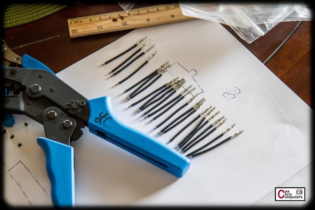
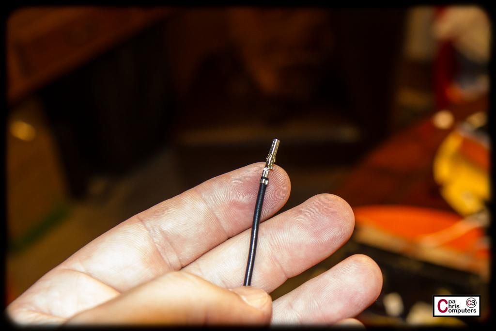
Next I got out the Lutro0 crimper and the ATX pins and went to work putting a female ATX pin on one end of every piece of wire....
I didn't take the time to go up to the studio and use the tripod and good lighting....but take a look at the crimps that these pins/crimper can do. Top notch quality tools here. I can get better crimps more often with these tools....than I could with my MDPC crimper.
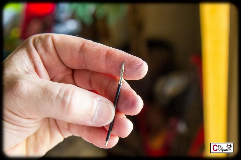
Look at those brave lil' soldiers.....
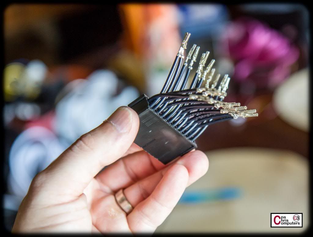
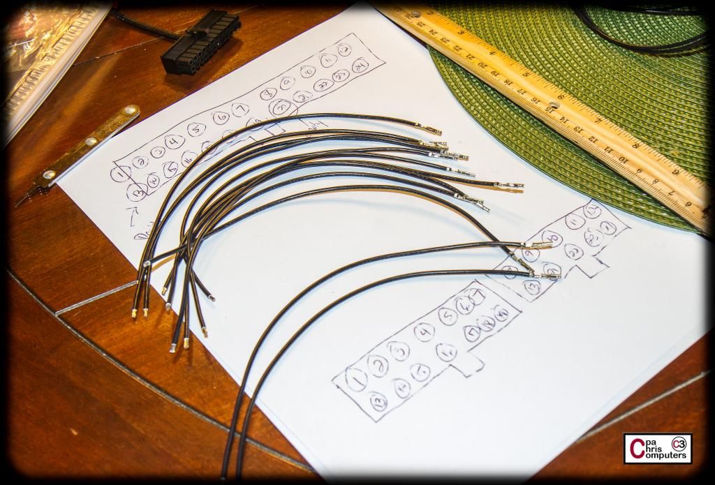
Next I put a male ATX pin on the other end of the wires. If you count them, you'll notice that we lost a few soldiers on the battlefield. Even with nice tools, you will occassionally get a pin that gets crushed the wrong way in the crimper. I wanted all these to be perfect, so any crimped pins that had imperfections were tossed. I had to make up a few extra wires in the end.....
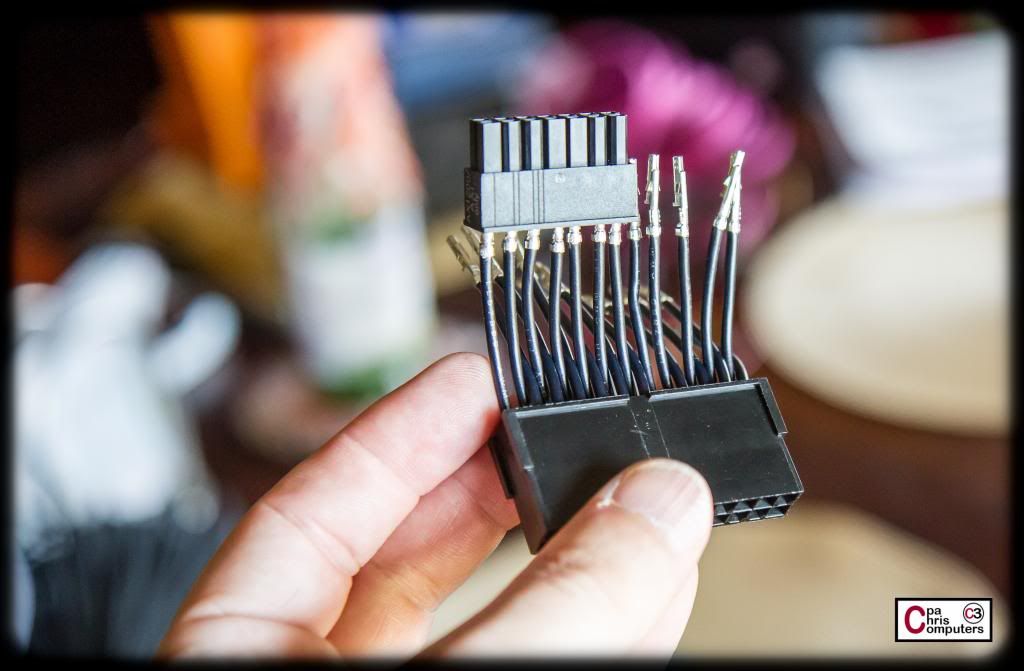
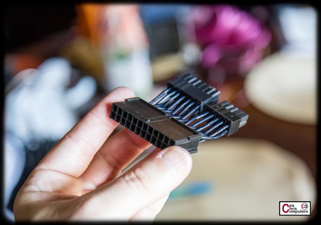
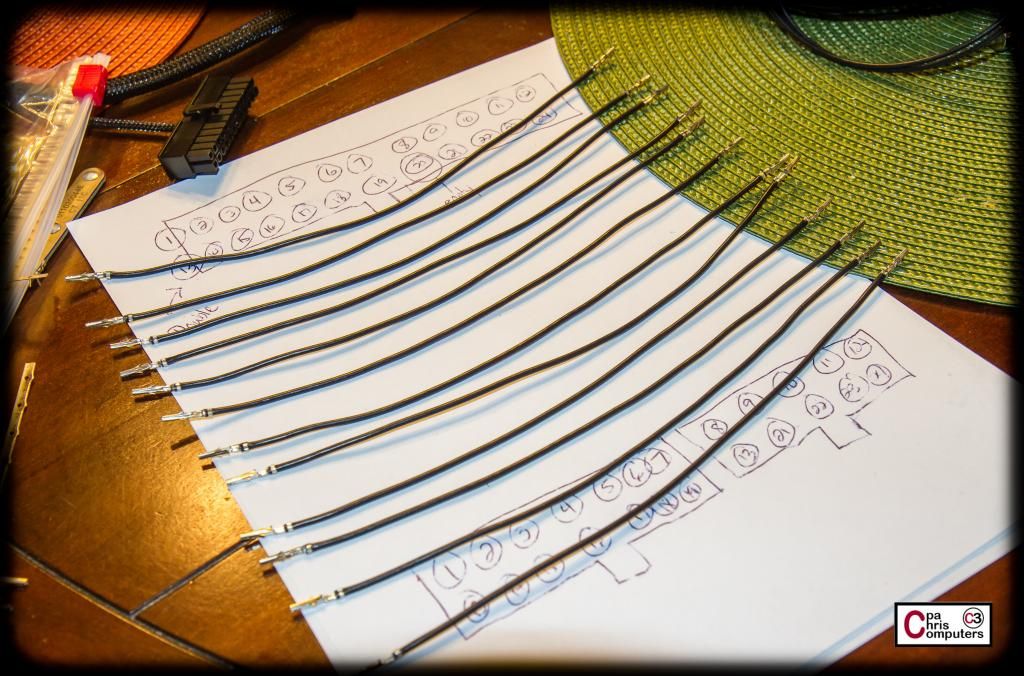
The time has come to put this thing together. I started with the male pin side of the wires, and inserted these into the proper holes on the male connector. Then I used the slack in the wire to bend the top row down to the bottom, and the bottom row up to the top.
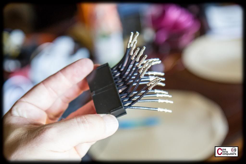
Then I got the PSU connectors and started to insert the female pins from my short wires into the connector. It's this step where you will be glad that you measured carefully and that every wire is the exact same length. If you have one wire longer or shorter than the others....it gets tricky to get everything to lock in place.
After I had secured the 14 pin PSU connector, I added the 10 pin PSU connector also, and snugged all the pins in until I heard that satisfying 'click'.
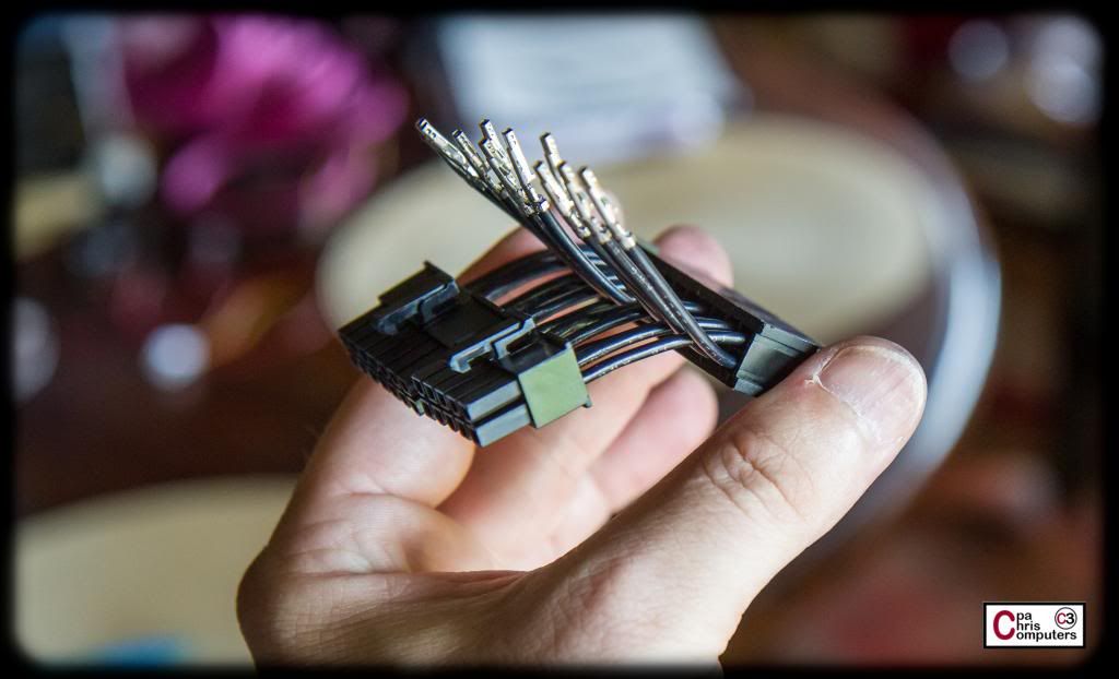
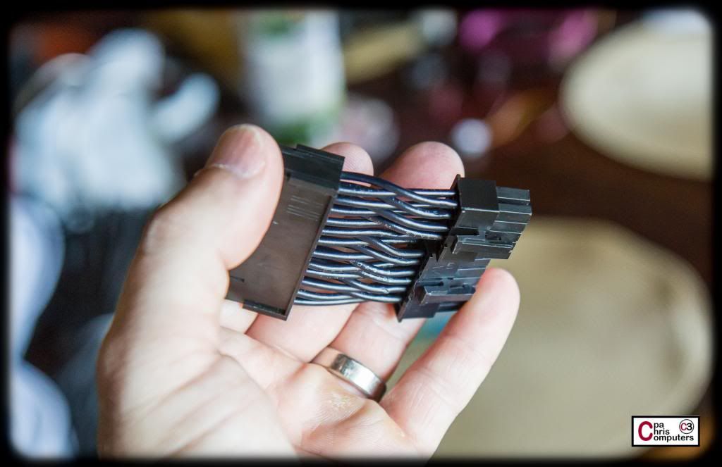
This I used the little bit of slack in the wire to bend each wire back far enough to insert the other row of wires into the connectors. This step is where you will find out if your wires are long enough. Too long....and it looks messy. But too short...and it's very difficult to bend them back far enough to insert the pins......
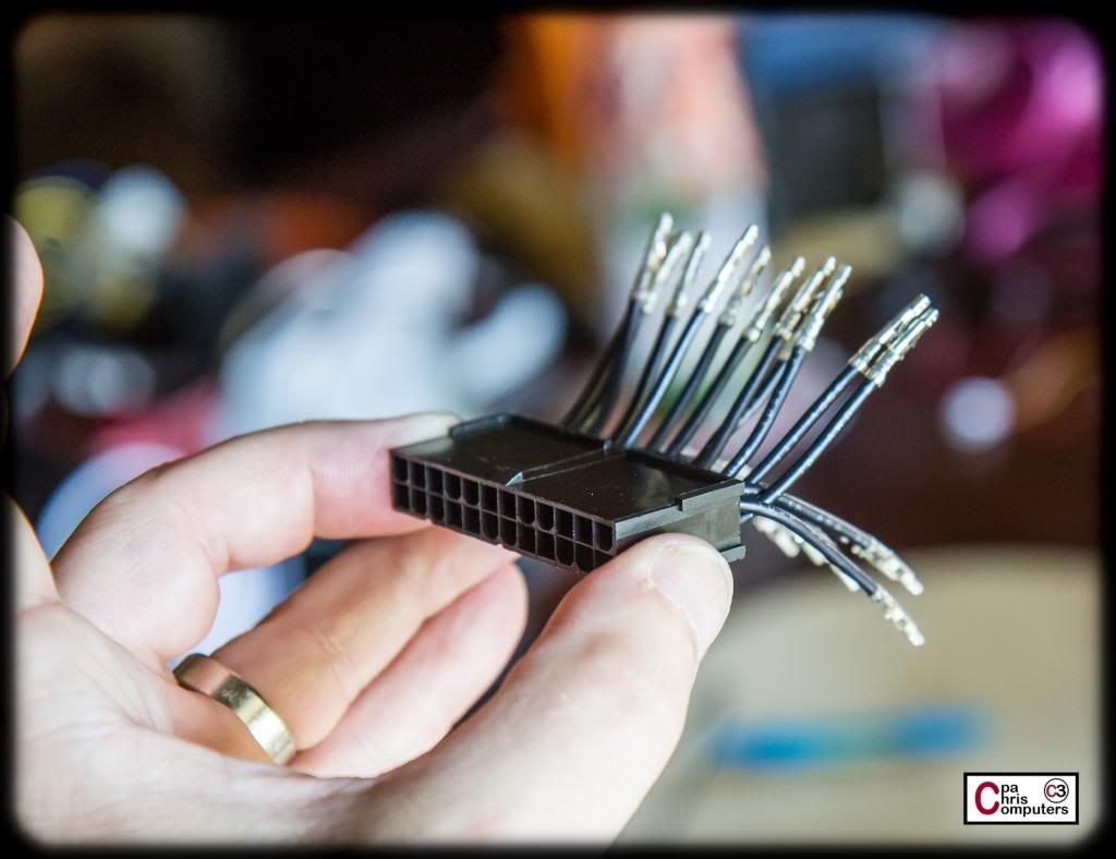
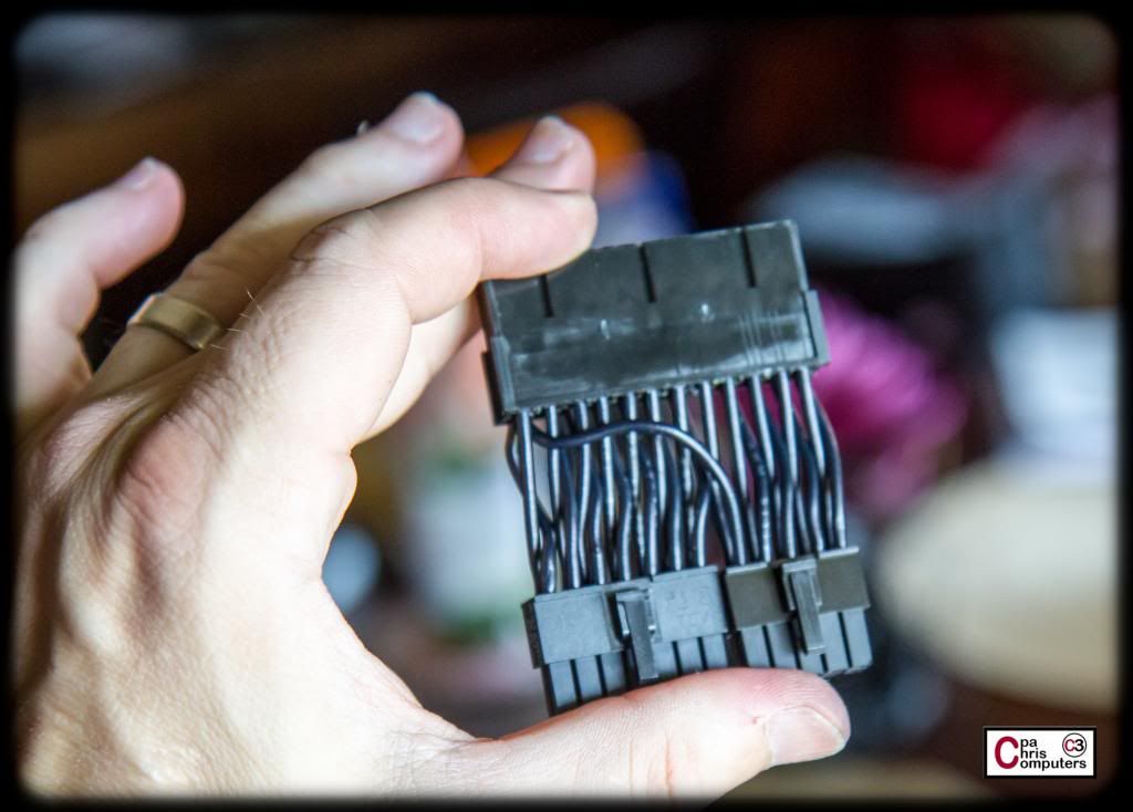
All that was left at this point was the double wire. The pins I was using had large enough wings where they were able to hold two of these 16 AWG wires nicely.
When I did this for the BBBB, I also put some sleeve on the wires. I chose not to for this one, because I found that it created a huge bulge in the connector since basically every wire has to wrap around and down before getting to it's connector. It actually looked much cleaner with just the black wire and black connectors. Additionally, you won't see this connector when the build is done. The PSU side of the 24 pin connectors are beneath other connectors and not seen.
So....that's all for this step. Now, I'm off to do a big pink dye batch and turn the rest of my white Telios into a gorgeous pink. Need to be ready when [@]JennG[/@] makes that final selection!
Text update....
Finished up my big pink dye batch last night. I'll have some pictures to post tonight.
Also, Jenn finalized on her 24-pin selection. It was also one of the crowd favorites from the voting. She chose 3-4 from the last batch, which was this one:
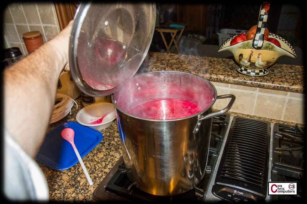
Pink Dye Bath!!
I kind of walked through the step-by-step awhile back when I did the test batch, so I'll skip the narrative on how to make the dye bath this time, and get straight to the pictures.
Mmmmmmmmm......what's for dinner??
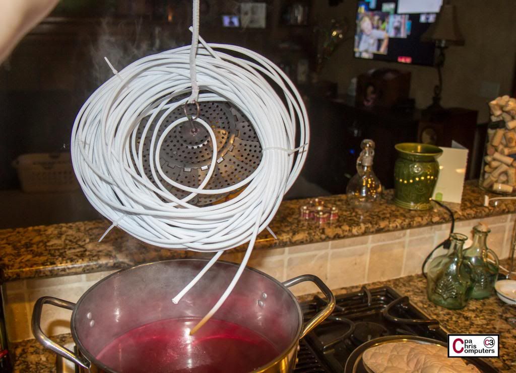
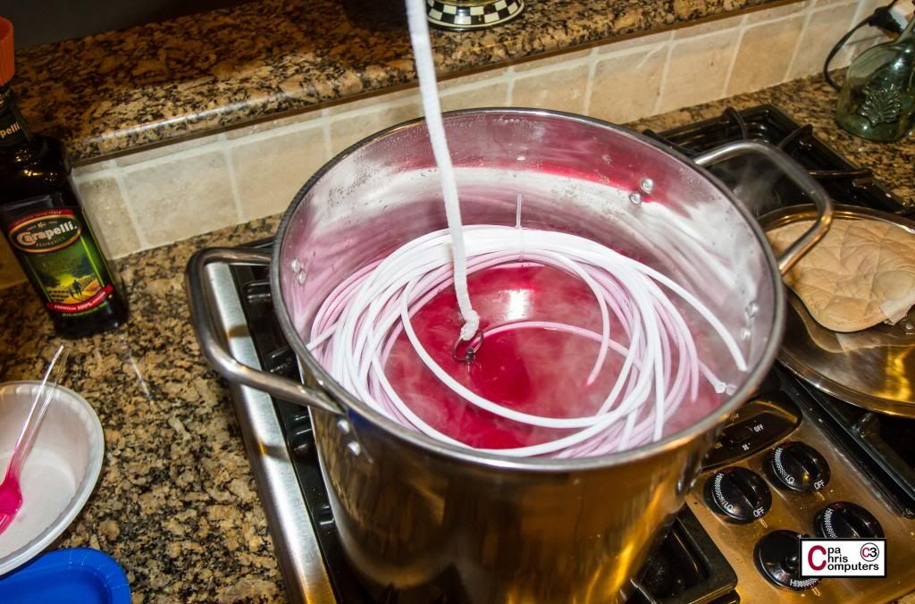
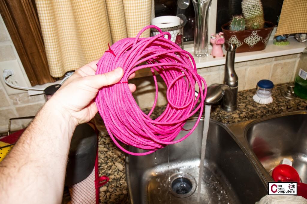
I tied up a loose roll of about 75 feet of white Telios, and put it on a strainer plate, so that it wouldn't sit on the bottom of the pot. Away from the direct heat.
I tied some pipe cleaner around the strainer plate so I could raise and lower it and check on the progress of the sleeve in the dye bath.
Coming along nicely after just 5 minutes.....
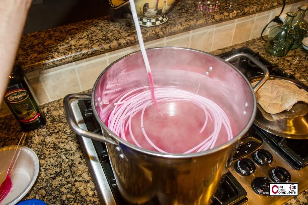
...and after about an hour of cookin'.....it looked like this!
I kind of lucked out with how nicely the color matched my case....without having to do a lot of trial and error dye mixing. Anyway....now I've got some pink sleeve.....so I'll get started on that 24 pin right away. Kind of anxious to get rid of all the excess power cabling in the case already.
Time to make that 24 pin!
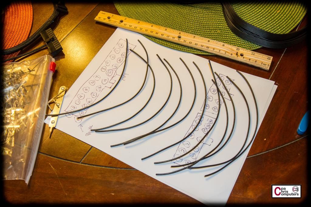
I'm going to make this extension have a pretty extreme and tight bend in it (more than 180 degrees). If you want your 24 pin to have a nice curve and keep it, you have to make the inside row of wires shorter than the outside row of wires. There is a formula you can follow if you want a precise down to the millimeter measurement, based on how many degrees of bend you will have, but my rule of thumb is to use 1/4 inch shorter on the inside row for every 90 degrees of bend you want in the extension. I'm going to have a little more than 180 degrees, so I'm going to make my inside wires about 5/8 inch shorter than my outside.
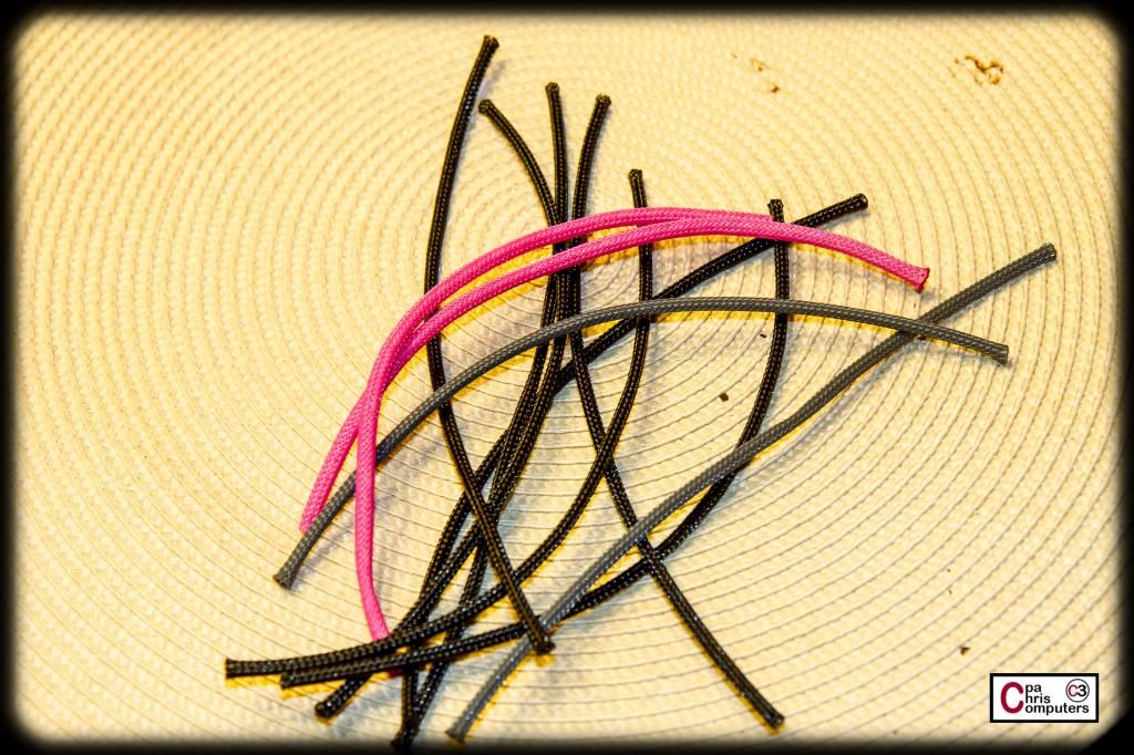
Let's make the outside row of wires first. Based on a couple of trial and errors, I settled on 8.5 inches for the length of the outside row. This length created a nice snug fit with a tight bend. No excess wire here. It's all work and no play. So I cut myself 12 pieces of my 16 AWG Lutro0 Customs special wire into 8.5 inch lengths....
There they are....all lined up and reporting for duty.
Then I used my Knipex wire strippers to take off the EXACT same amount of insulation on each of these soldiers...
They didn't mind one bit.
Then I used my Lutro0 crimper and pins to make some more of those PERFECT crimps on one end of the wires.
I always do just one end first, because I can run through these all without having to worry about rotating the pin in the right direction before crimping.
For the second pin, I always make sure and lay out the wire on something flat and ensure that I'm crimping the pin with it rotated in the right position on the wire. For this extension, both pins needed to be facing up the same direction. If you forget to make sure they are lined up....it causes grief when you go to insert them into the connectors, because you'll have to be twisting the wire/sleeve around to get it to fit into the connector. No-bueno. So make sure you have them lined up correctly.
Stripped and crimped. Sounds like a bad 80's movie......
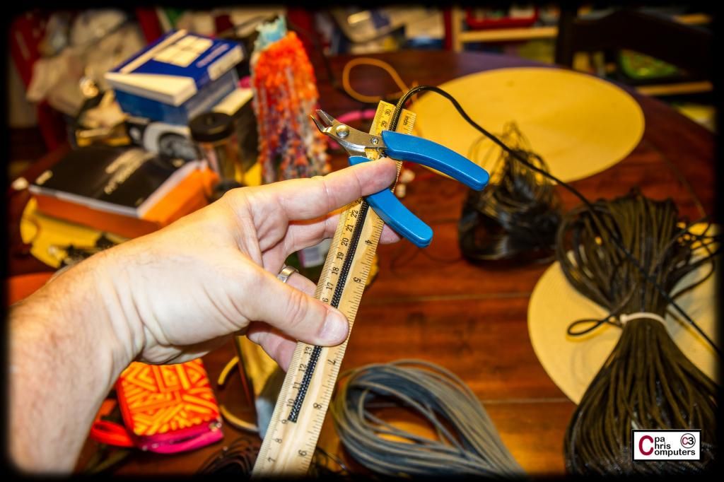
Next I cut lengths of my sleeve to use. I've found that if I cut the sleeve a little less than 1/4 inch shorter than the wire, that it comes out just about perfect for the shrinkless method I use. Of course, this 1/4 inch will depend on how much insulation you take off, and how tight you stretch the sleeve. But for me....a smidge less than 1/4 inch shorter works nicely.
I always touch the ends with some flame and taper them at this point also. 2 grey, 2 pink and 8 black. That's what I need for the outside row I'm working on.
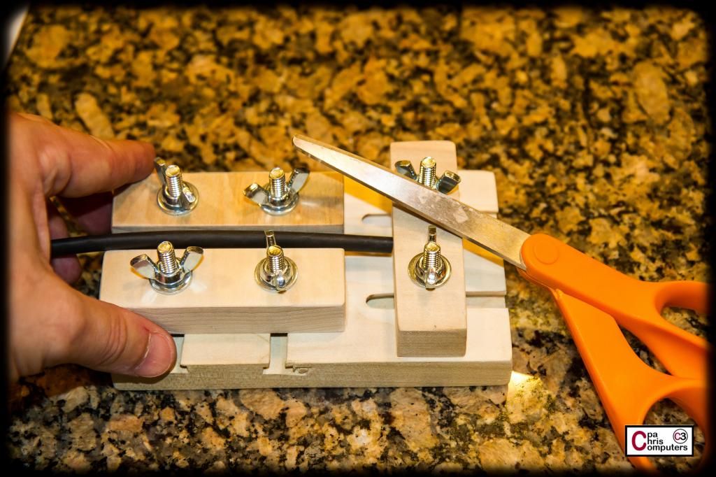
Now I need some heatshrink for my shrinkless method. I've always found that kind of funny. Took out my jig and a pair of scissors, and went to work cutting some up.
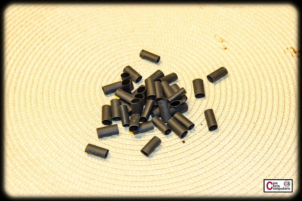
Perfect. I mentioned this awhile back, but I never could get consistently good results using an exacto knife or box cutter or razor blade. But with a pair of scissors....I can cut up 50 pieces of perfectly sized shrink in about 2 minutes. It's quick. And I love being able to adjust to get the perfect size I need for whatever I'm doing. Nice lil' tool....
Look at them. They don't even know they are about to get burned alive.....
Next steps were to cinch my wires into a piece of sleeve, and melt the sleeve onto the pins at the end of the wire. If you've never tried shrinkless.....give it a shot. Plenty of good videos available, so I won't recreate the wheel for you. But check some out and then give it a go. I find it more forgiving than using heatshrink, and it secures the sleeve MUCH better than when using heatshrink. Since the sleeve is literally melted and formed around the first ridge on the pin....it's on there securely. It's not going anywhere. This lets me pull the sleeve much more tightly than I ever could if it was secured by heatshrink. Tighter sleeve....is nicer sleeve.
Oh Lord. I've now mentioned strippers, shrinking and tighter in the same post. I fear the gate has been opened for off-topic comments.
After completing the outside row, I went back and did all the same steps for the inside row, but I cut the wires 5/8 inch shorter than I did for the outside row.
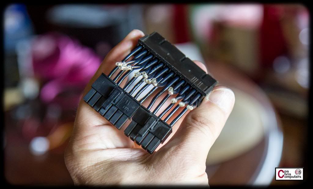
So....here is what it looked like after I got both rows.
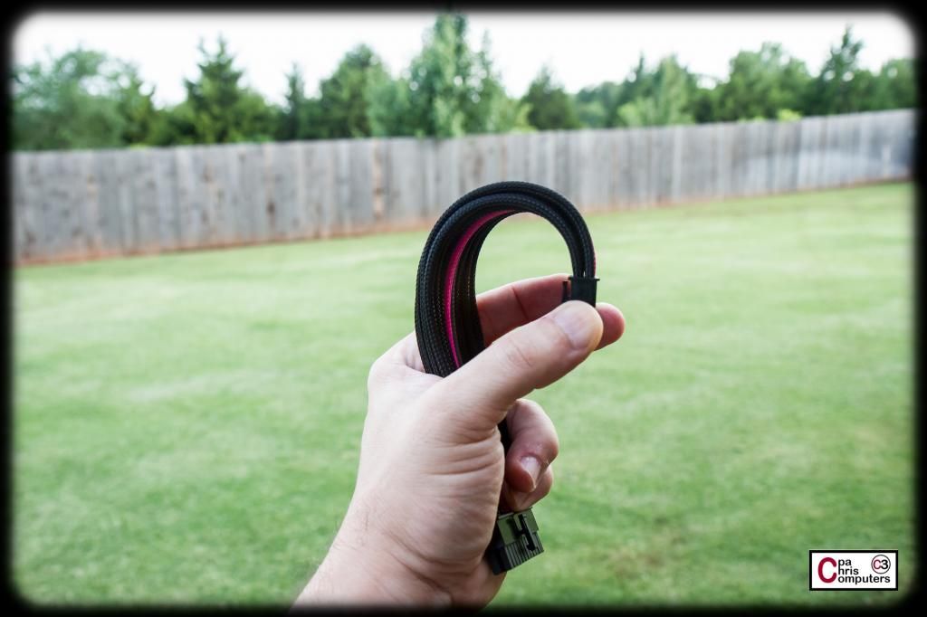
If you try and lay it flat, you'll see that one row (the outside row) has to buckle up since it's longer.
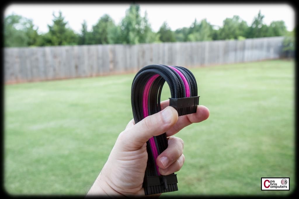
But have no fear. If you measured right, when you bend the extension in the shape you are going to use....all of the wires will magically snug up next to each other and look incredible!
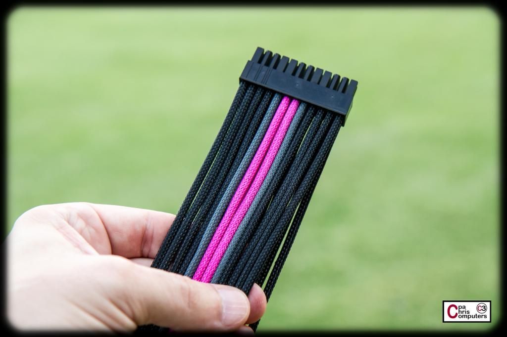
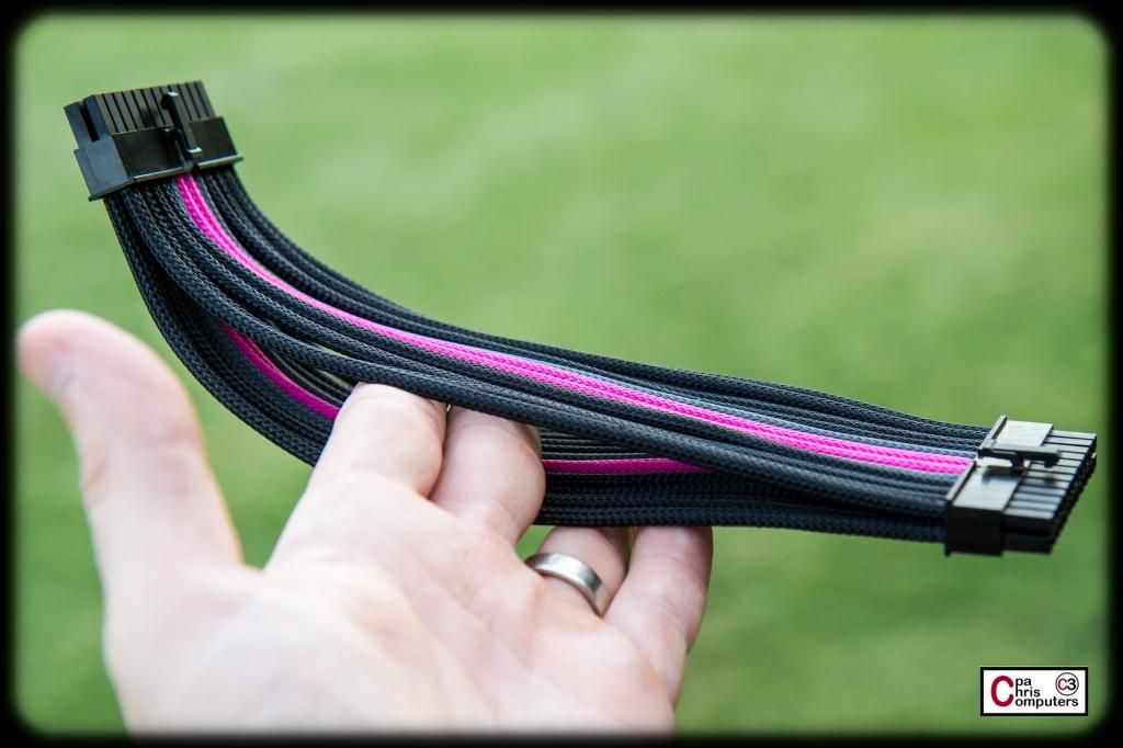
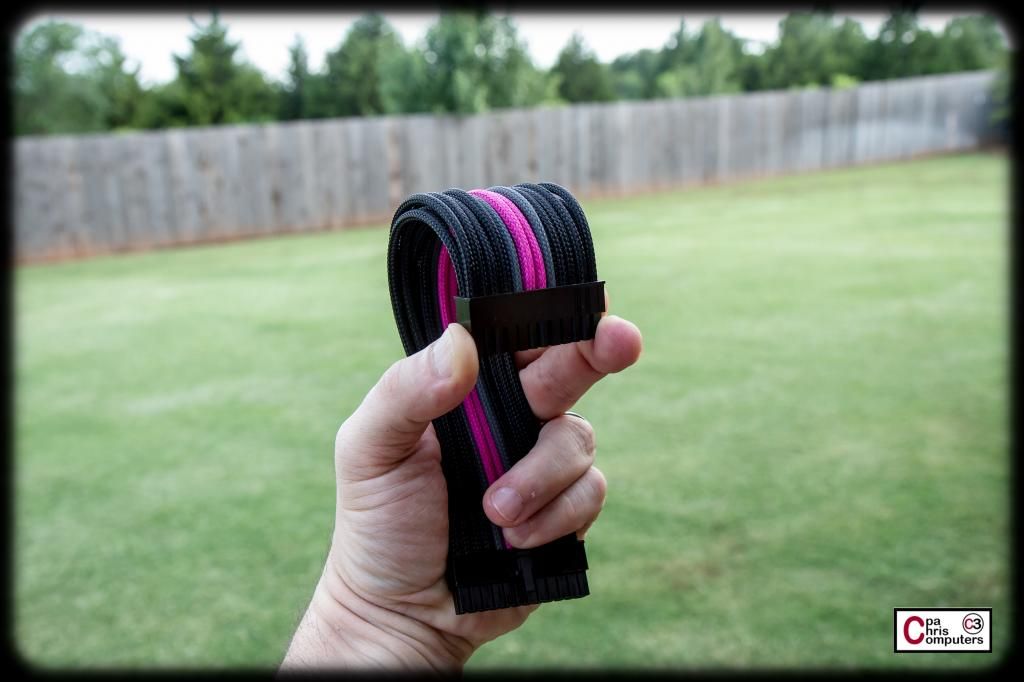
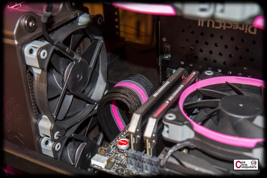
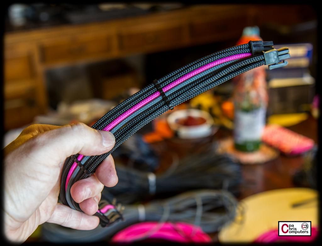
Here is what it looks like inside the build. It came out perfect length. There is not an inch of extra slack in the wire. Perfectly sized, and looking like it's a full one-to-one cable since the ugly doubles and cross-overs are all handled in the mini-cable right by the PSU.
I actually gave away a surprise with some of those pictures....and I'm sure the eagle eyed forum members will catch it. But I'll do a full post on it tomorrow anyway so it's not like I would have kept it a surprise forever!
Now....to test and see if I got everything wired up correctly, the first thing I did was plug it in and see if the computer would boot. Check.
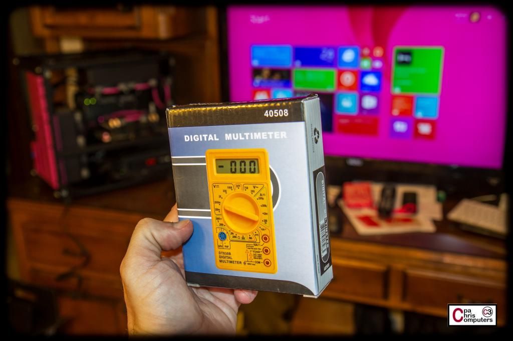
All voltage readings read normal in my Aida64 screens. But....I decided to test out one of my new toys anyway. I got this little multi-meter from Lutro0, and I hadn't used it yet.
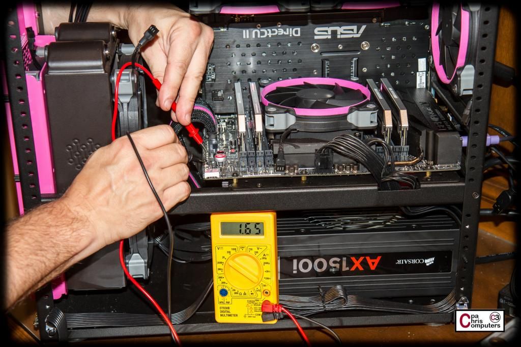
One of the very cool features of the ASUS RIVE BE are the places on the board where you can place probes and test the different voltages on the board. VCore, VTT, DRAM, etc. All of mine tested perfectly. I even tested the memory at 1.5v and at the XMP settings of 1.65 volts. The measurements I got from the motherboard were exactly what they should be under each scenario. Very handy tool and I love having that feature on the motherboard. Nice touch ASUS.
I initially tried some of the stealth cable combs from Lutro0, and decided that I liked the look of cable sewing better. So....next up on my project list is to do some sewing on the 24 pin. I'll also start in on the other motherboard power connectors. There are lots of ways to pimp your ride when doing a computer build. But custom sized cables is one of those things where you get a lot of bang for the buck. In my mind, nothing makes a build sharper than custom sized and sleeved cables for every connector.
ASUS North America posted a teaser on their Facebook page yesterday! Thanks ASUS!
https://www.facebook.com/asus.n.america
nice! keep up the good work man, i wish i could make even half of this rig for my girl
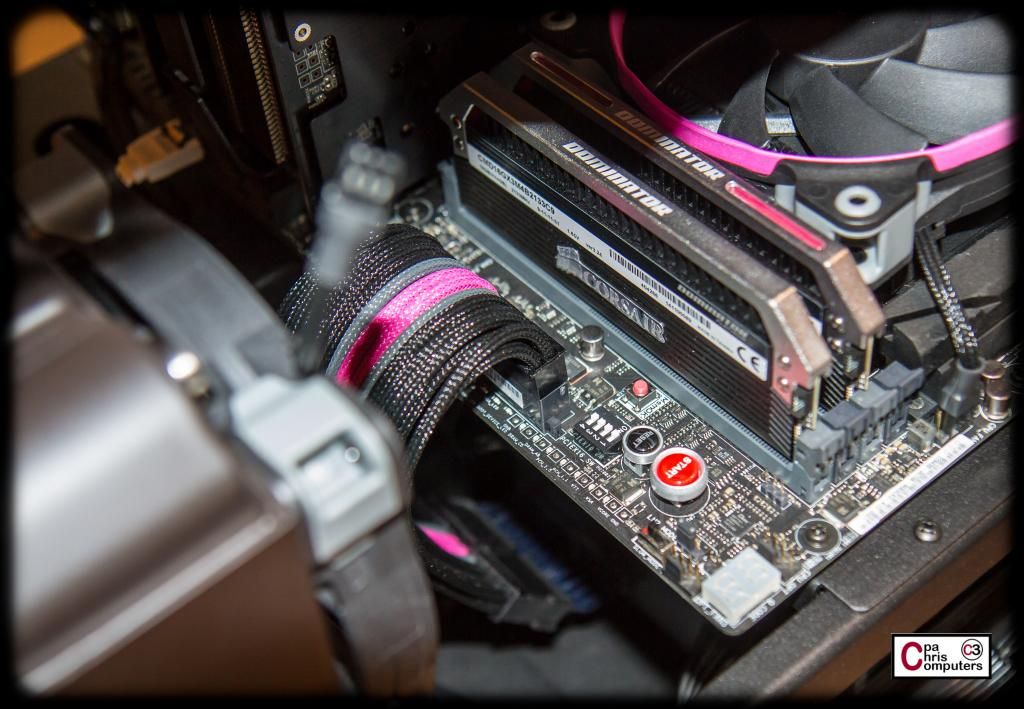
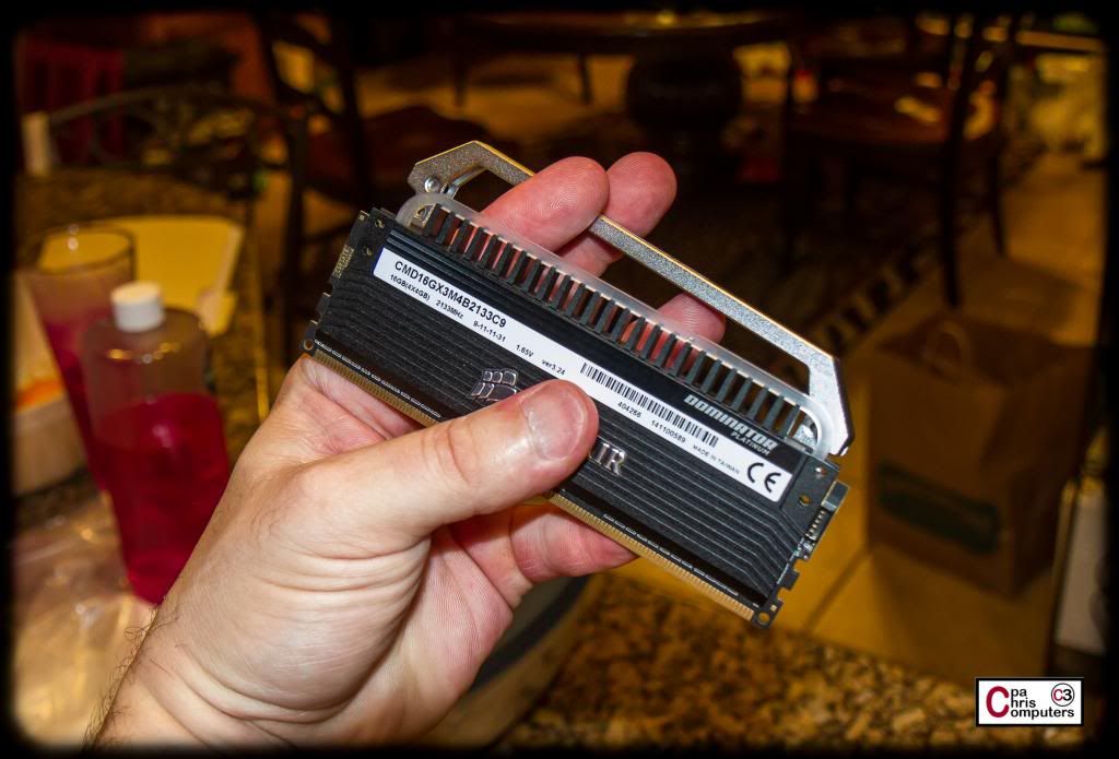
All right. I mentioned that my previous pictures gave away a surprise, and I think most people probably spotted it already. But in case you didn't, .....here are the pictures....
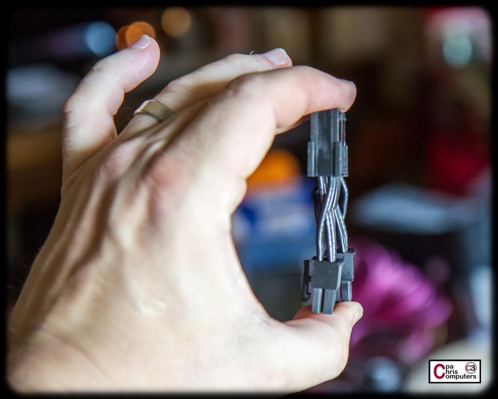
The Corsair Dominator Platinums have a removable bridge that goes over the heat sink fin, and serves to cast the light from the light bars downward on the ram. Take out the four small screws, and it comes right off. See the translucent light bar sitting on top of the heatsink fins?
The actual light bar is not attached at all. It was merely held in place by the bridge. The two ends of the light bar sit on top of tiny LED's inside the memory sticks, which light up the entire bar.
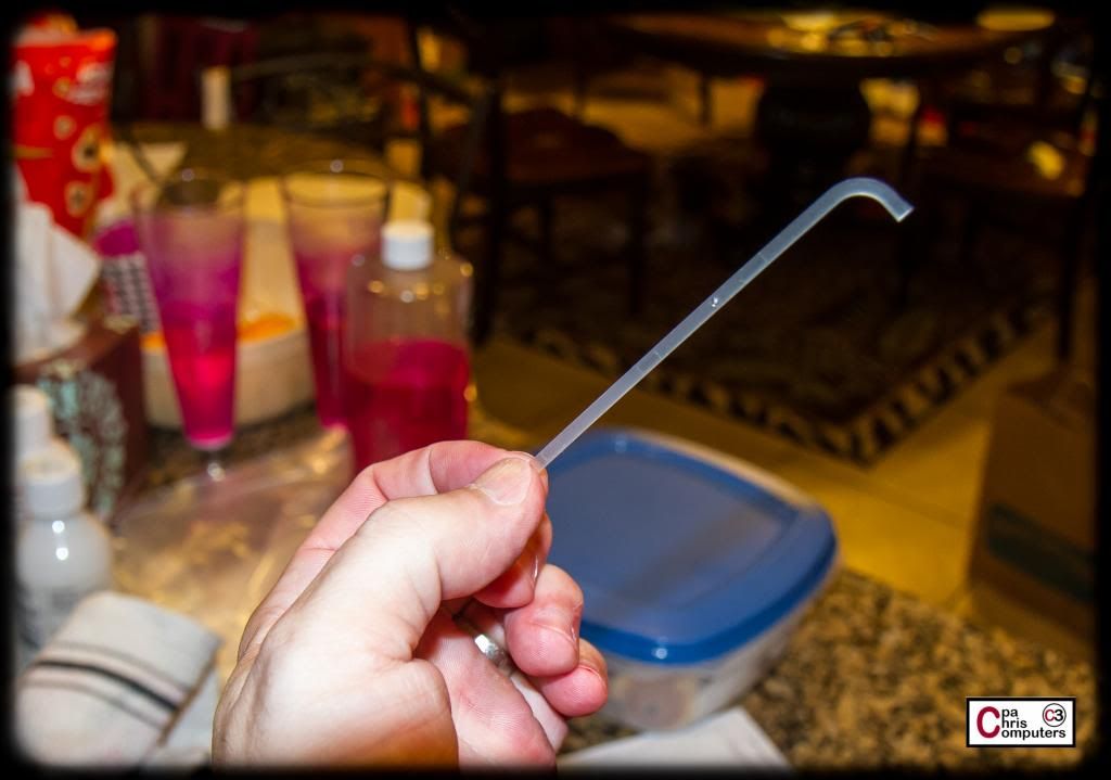
Well....you remember that big pot of dye that I used for to create my pink Telios? You can see where this is going, right?
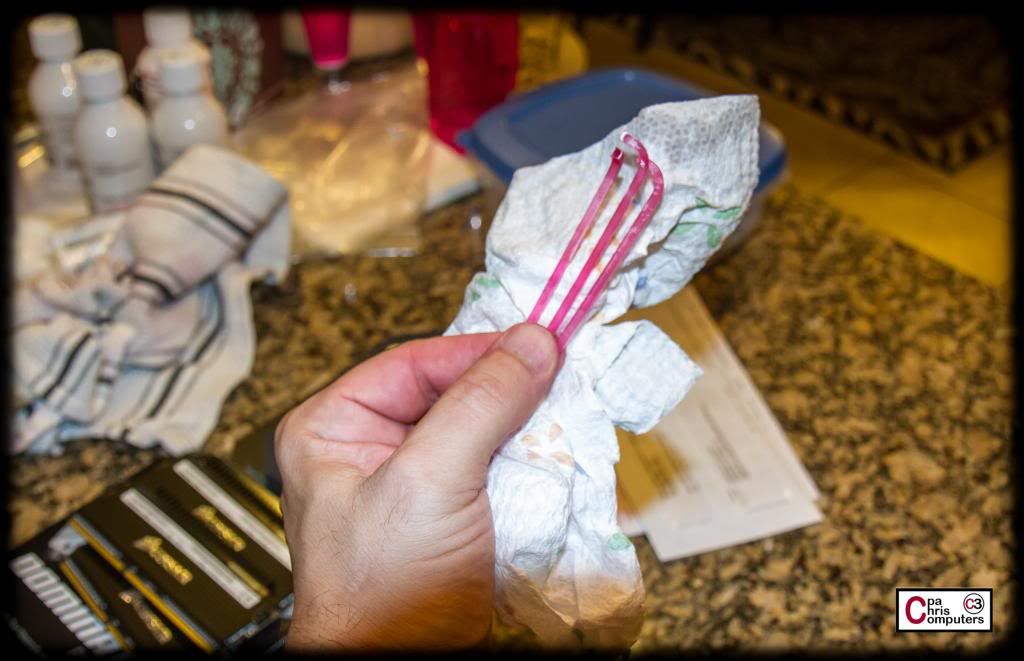
I threw the lightbars into the dye bath and cooked them for about 20 minutes. They took the dye real quick, and came out a gorgeous shade of pink!
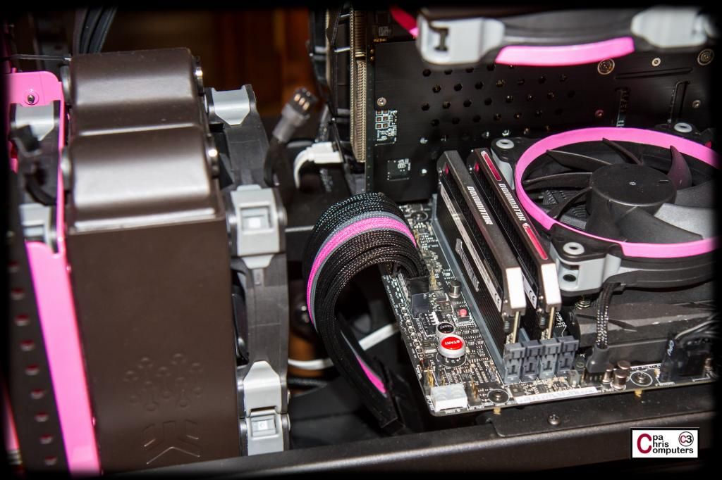
I reinstalled the light bars in the memory sticks, and put them back in the build. I turned the lights off and took some flash pictures....but then turned the exposure down far enough so that you can kind of see the neat lil' pink glow that is created.
I have the light bar upgrade kit installed in just one of the memory sticks right now. You can see the pink lights on top of that one stick. The top inserts are actually still clear....but the pink light bar from underneath makes everything appear pink on top also.
In addition to the one stick that has the topside cutouts....you can see on all the sticks the pink glow created at the edge of the memory sticks. In person, it creates more of a glow than I can pick up in the pictures, ....but you get the idea.
I think the pink glow looks amazing, but I'm going to try something else with these sticks also. You know the silver covered bridge that runs across the top of the sticks? I'm going to have that powder coated black to match the inside of the case. So the top of the sticks are going to be black....with those pink lightbar cutouts showing through. Can't wait to see how it looks that way! Will take 2 or 3 weeks to get to that step though. I'm accumulating all the stuff for my second powder coating batch right now, and then I'll ship off the pieces to CaseLabs. I'll have some other pieces also. Faceplates, mounting brackets, etc.
I'm still working on stitching for the 24 pin. Got one more row done tonight. Need 2 or 3 more....and it will be done.
More soon!
I finished the stitching on the 24 pin last night. I find it pretty easy to watch TV while I do this. On the BBBB, I watched most of the Breaking Bad seasons while I stitched that bad boy up. Last night, I started watching Game of Thrones with Jennifer (future owner of the PPPP) while I stitched. Good show. Watched two episodes and finished up the 24 pin......
I started doing the cables for the other motherboard power connectors today. There is an 8 pin and a 4 pin at the top of the board. That puts 6 wires in a row across one side if I bring the two connectors together. Can't really duplicate the pattern used for the 24 pin....but I think I'm going to do a BBPGBB theme, which would be similar. At least that's what I'll start with and I'll let Jenn steer me differently is she chooses....
For the routing, I'm going to stitch both cables together on top of the motherboard side, so that they turn into one seamless cable. After feeding it down through the cable management cutout and below the motherboard, then I think I'll secure it to the underside of the motherboard tray so that you can't see it (above the PSU), and then do a loop down around in front of the PSU to plug it in.
It's a shame, because it will barely show this way.....and the cable itself is gonna be pretty.
This power cable won't take too long, so I may finish it up tonight......
Finished up the motherboard power cables....and 2 more episodes of Game of Thrones.
Here she is.....
The ASUS board has a 8 pin and a 4 pin connector, so what I've done is joined the cables together going across....so I can use a similar pattern to what we did for the 24 pin. I left off the connector on one end, because the cable management cut-out is small enough where I couldn't fit the connector through without scarring it up....
Here she is inside the build.....
I'm using the cable combs on a temporary basis to help train the cables, but I'll eventually do some stitching to keep it nice and tidy.....
It's amazing to me how much custom length cables can clean-up the look of a build.....
Notice how the 8 pin cable starts out separate from the 4 pin cable (they have some space between them on the board), but come together as one cable before disappearing underneath the motherboard....
Need to figure out my GPU power cable path now, and get started on those. May take a break and work on some fan wiring just for a change....
Very nicely done cabling and sleeving....
Is there any guide for the stitching pattern you follow ?
Greatest idea ever, doing this with my rig now.
You and this build finally gave me the drive to finish sleeving my Seasonic
Thanks! Try this link. Pongo put together a pretty good tutorial that was the basis for what I started doing. His cable work was insane!
Hope you're not cursing me by the time you're done.
 Posting Permissions


 Reply With Quote
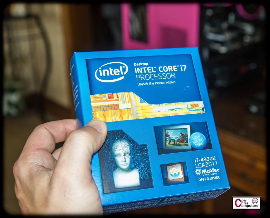


Bookmarks