

You bet. More soon!Originally Posted by Revv23


You bet. More soon!
Decided to take a look at some different coolants today....while I wait on the FedEx dude with my ASUS package.
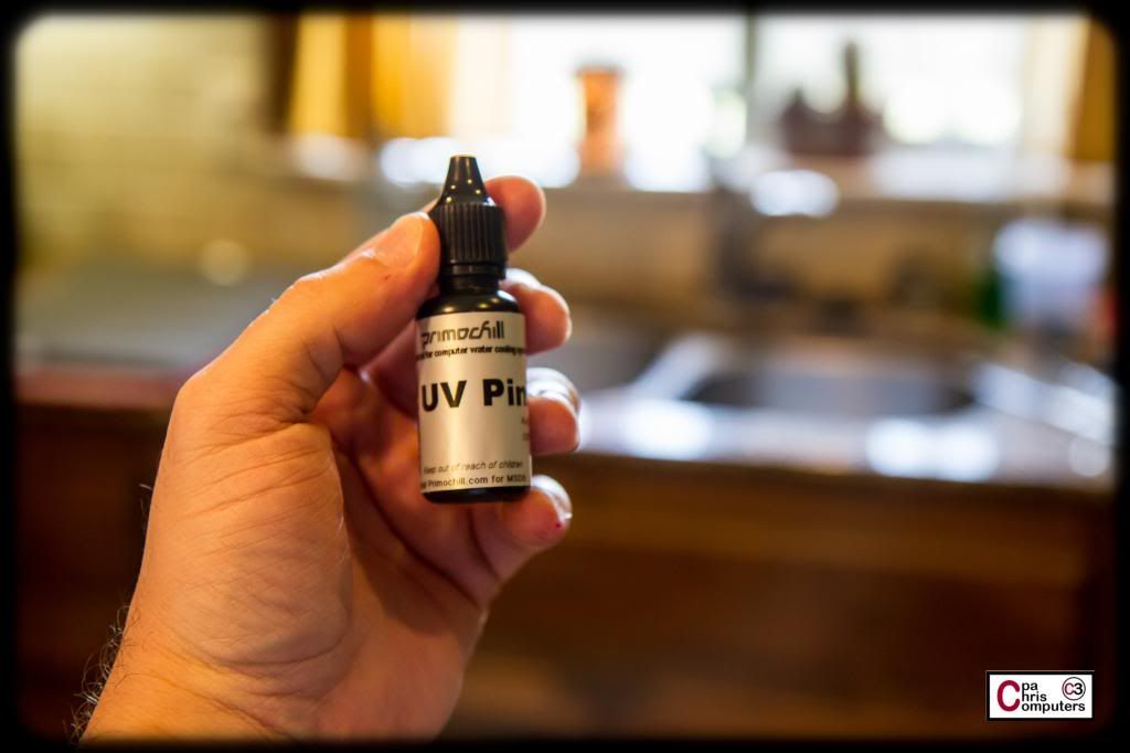
First up....Primochill UV PInk Premixed
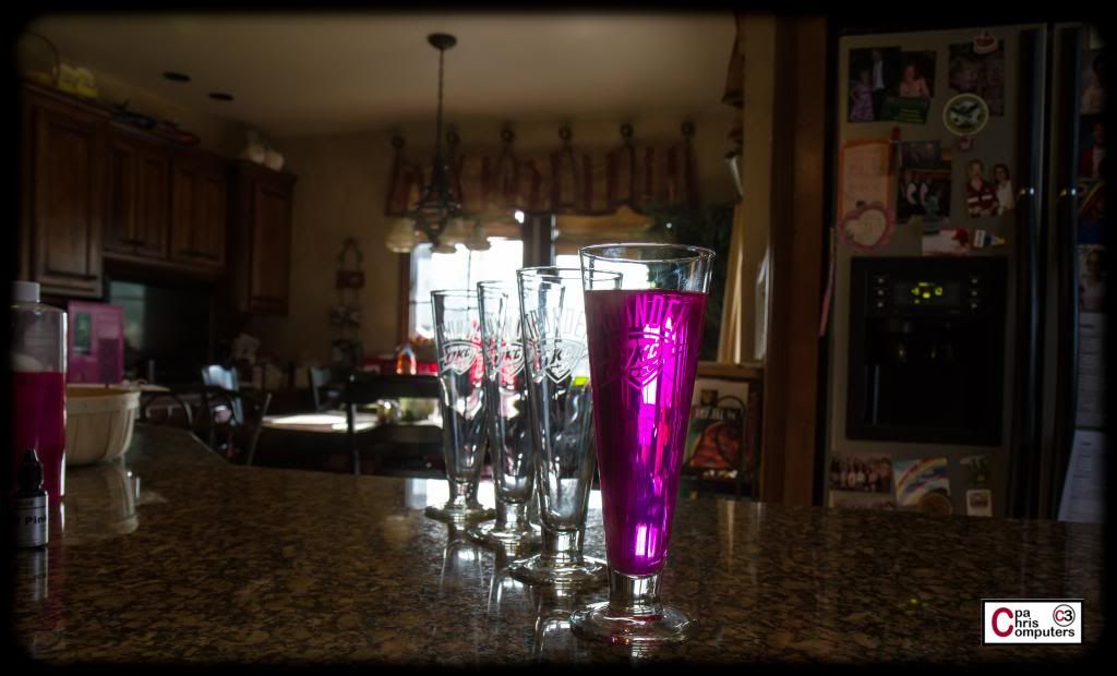
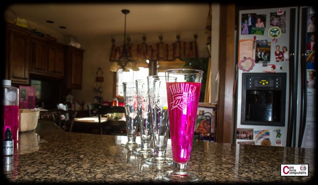
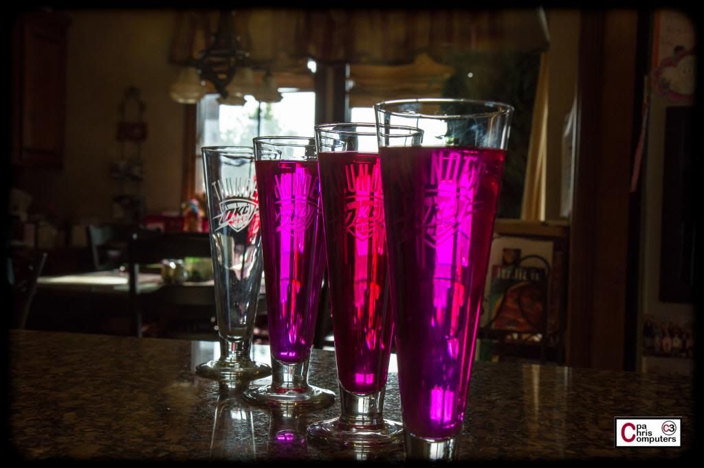
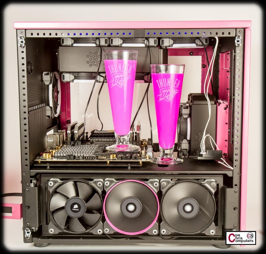
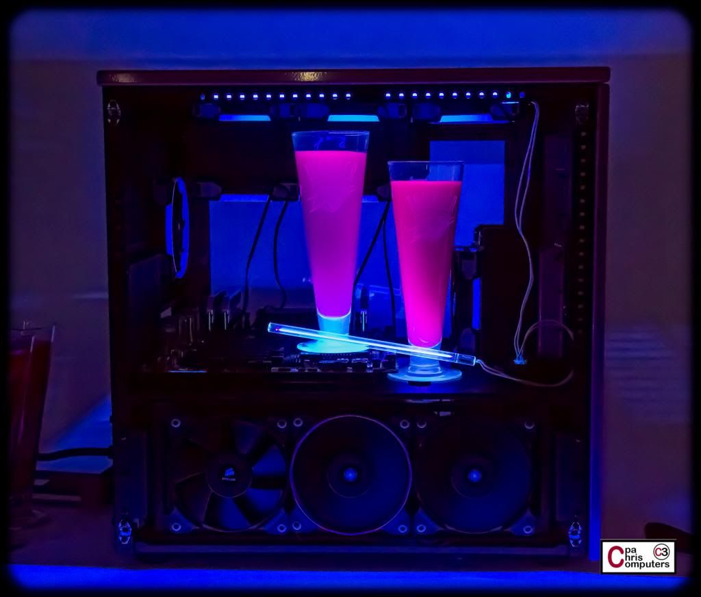
Because we are in the middle of the Western Conference Finals....You are all going to be treated to seeing the coolants in my Thunder pilsner glasses.Go Thunder! I'll take one pic with the flash off....
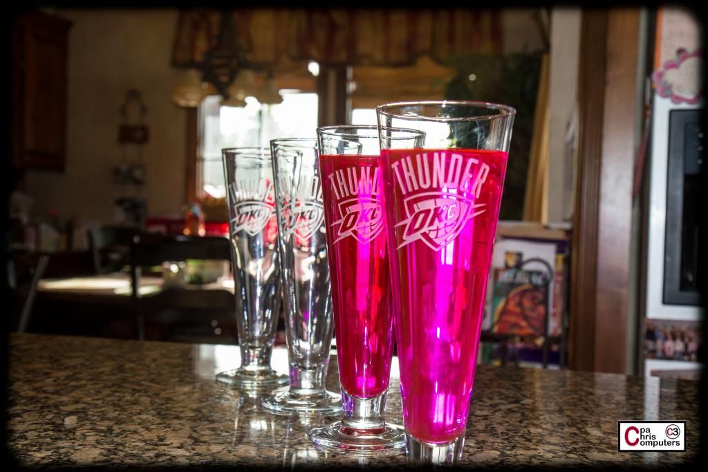
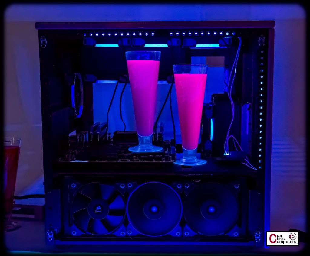
....and one pic with the flash on. Because it looks a little different both ways.
You can see that the coolant is very translucent. Not only can you see light pass through, but you can see images and shapes through the coolant.
Next up...Primochill UV Pink Dye. I wanted to see if it was the same hue as the premix....and see if I could alter the hue by changing how much dye I put in.
With about 7 drops....it looks almost identical to the premix. From front to back: 1) Primochill UV Pink Premix; 2) Primochill UV Pink Dye (7 drops)
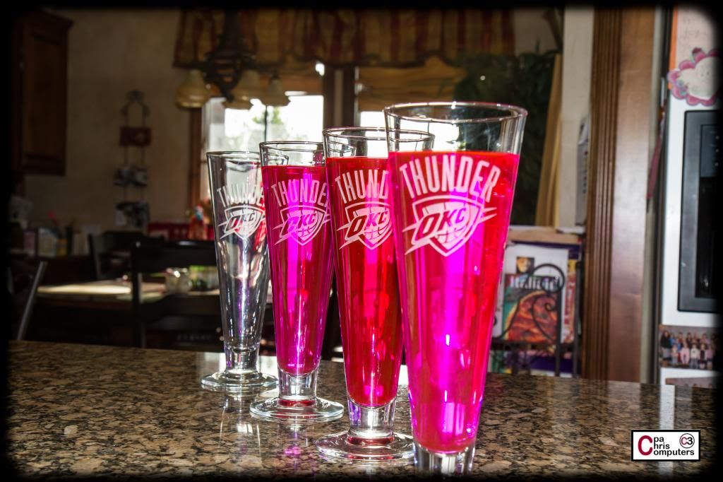
I decided to add a few more drops of the pink dye....and see what the color did. From front to back: 1) Primochill UV Pink Premix; 2) Primochill UV Pink Dye (10 drops). Tough to tell in this picture....but it seemed to be turning more red. Not really a darker pink...but more red.
To see if it was really turning more red like I though, I added 10 more drops. You'll see that in the next picture.
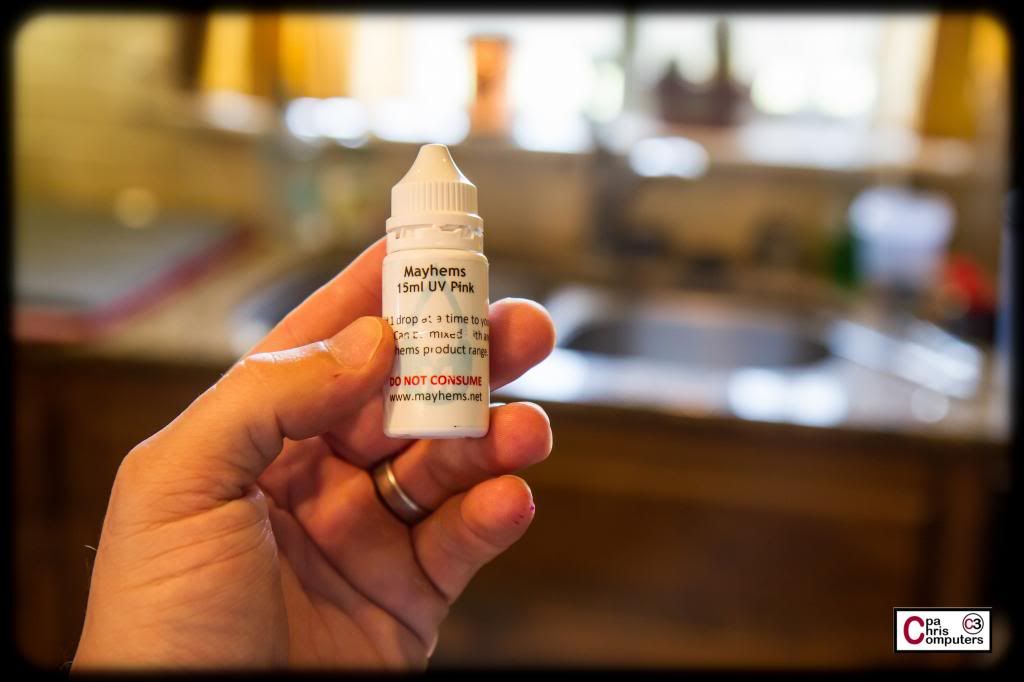
Next up....Mayhems UV Pink Dye.
I used about 7 drops here also. It is a very close match for the Primochill premix (or the dye with 7 drops). You'll notice in this picture that the Primochill dye with 20 drops is much redder than the others. From front to back: 1) Primochill UV Pink Premix; 2) Primochill UV Pink Dye (20 drops); 3) Mayhems UV Pink Dye 7 drops.
Flash on...
....and flash off.
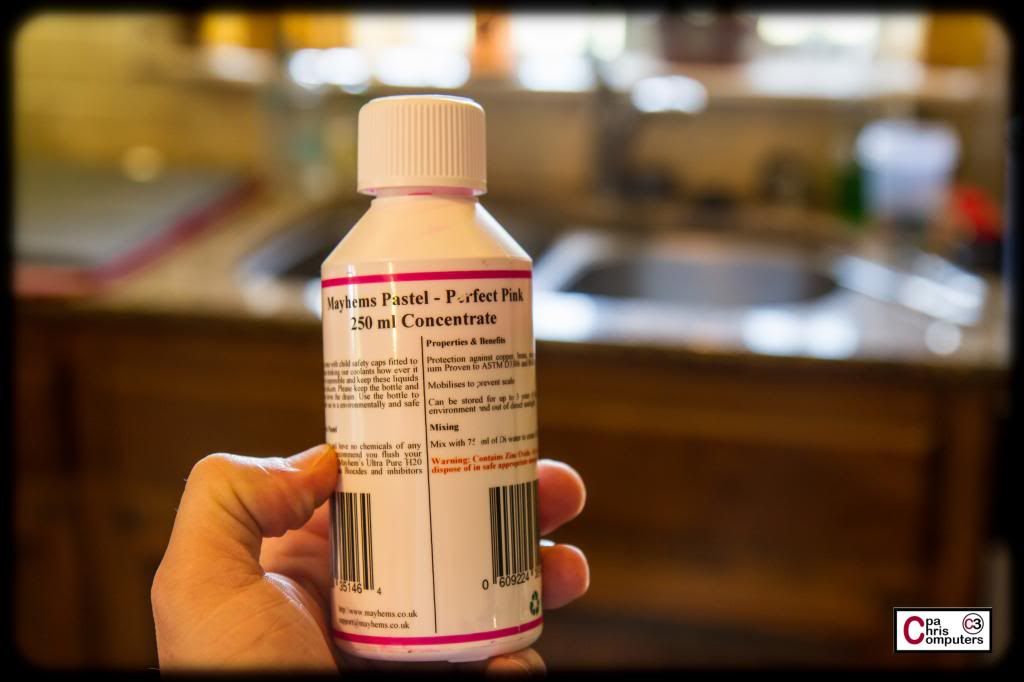
Next up....Mayhems Pastel Perfect Pink Concentrate.
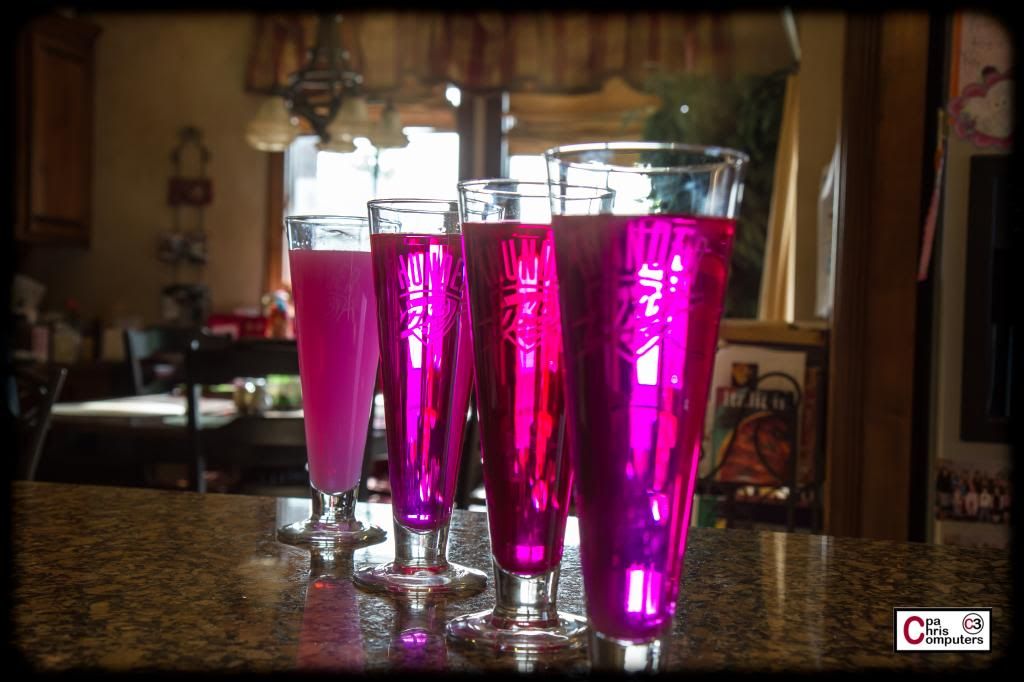
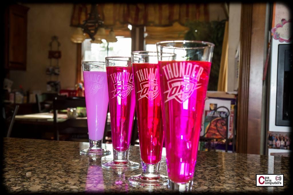
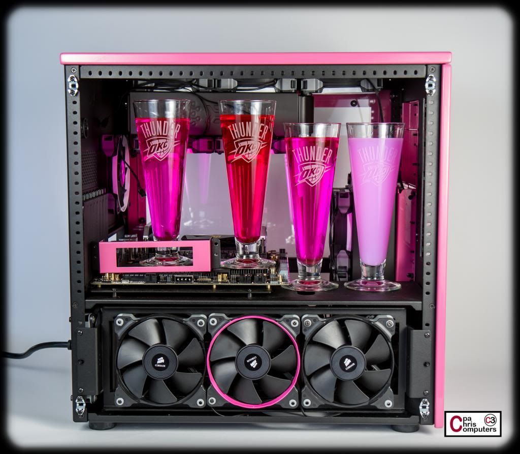
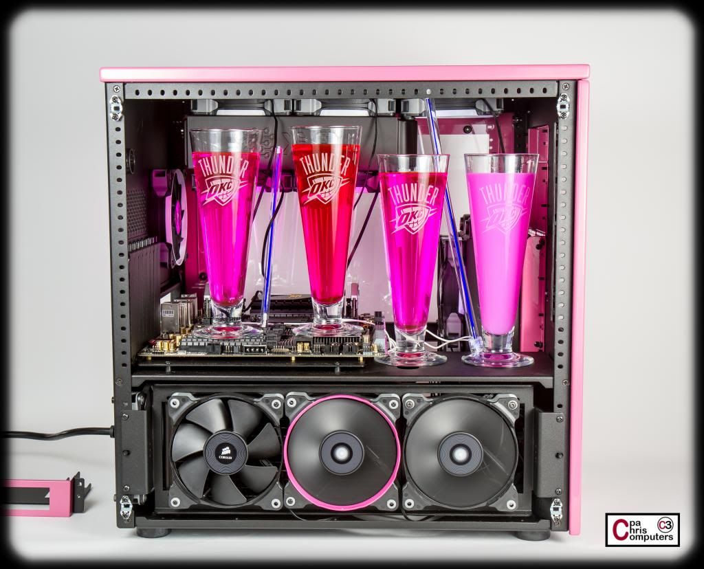
From front to back: 1) Primochill UV Pink Premix; 2) Primochill UV Pink Dye (20 drops); 3) Mayhems UV Pink Dye 7 drops; 4) Mayhems Pastel Perfect Pink.
Flash off....
Flash on....
Take note of how the pastel pink is almost completely opaque. No light shines through it...and you can't see shapes behind. it. Very different than the other three.
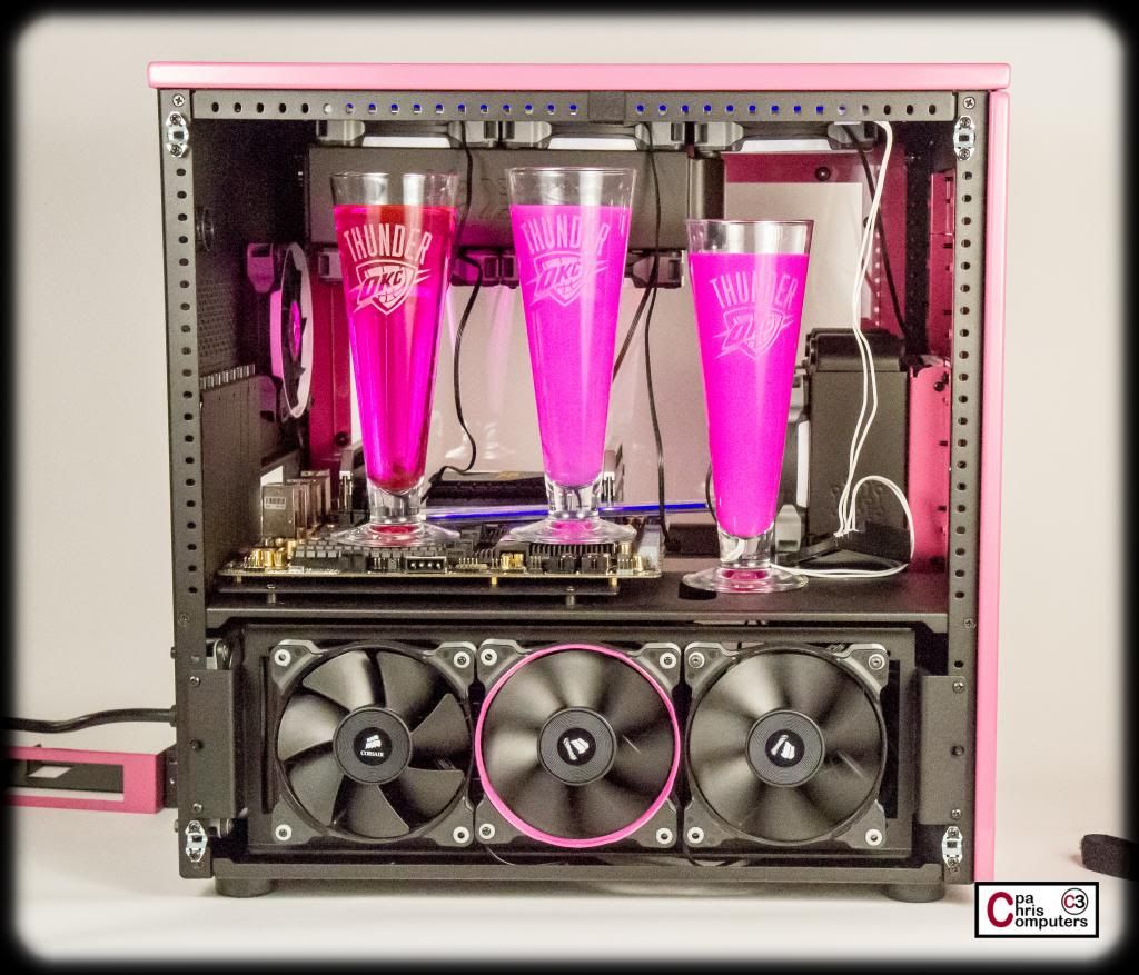
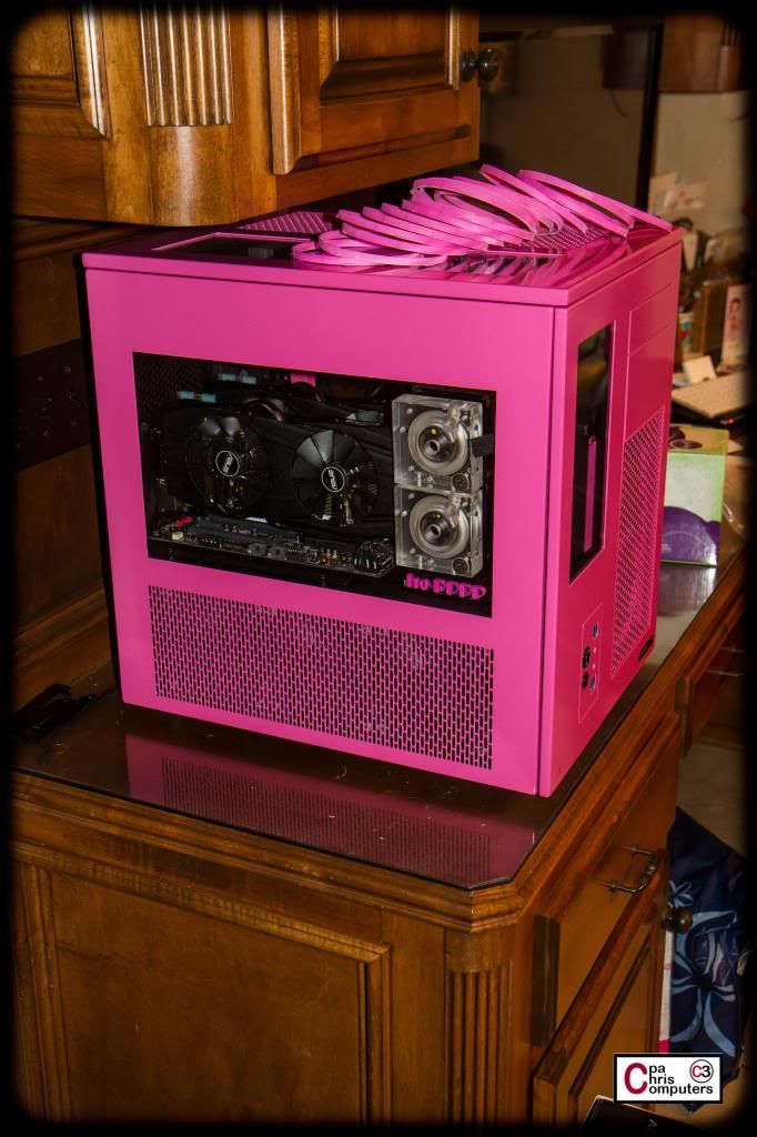
Let's take a look at them in the case....to see how close the pinks are to the case color. These are in the same order...but are now left to right, instead of front to back.
While I like the way they look....none of them are a dead-on match for the pink case. #2 clearly is too red, so I think I've learned that less of the pink dye will create a better match for my case than more of the pink dye. But even the other two translucents (#1 and #3) are a much brighter pink than my case. They make the case look much more mellow than it does by itself....because they are so bright. And #4, I like....but still not the right shade. It's more of a bright gumball/cotton candy pink. So....whichever one I go with, I'm going to need to do some experimentation on adding in other dyes in small amounts to get closer to the color of my case.
When I do that I'll make sure do some pictures along the way. Color matching is always kind of fun.
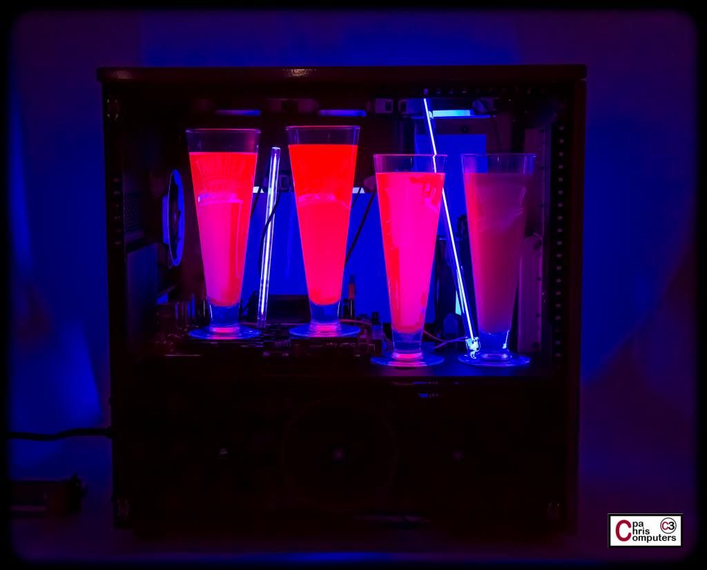
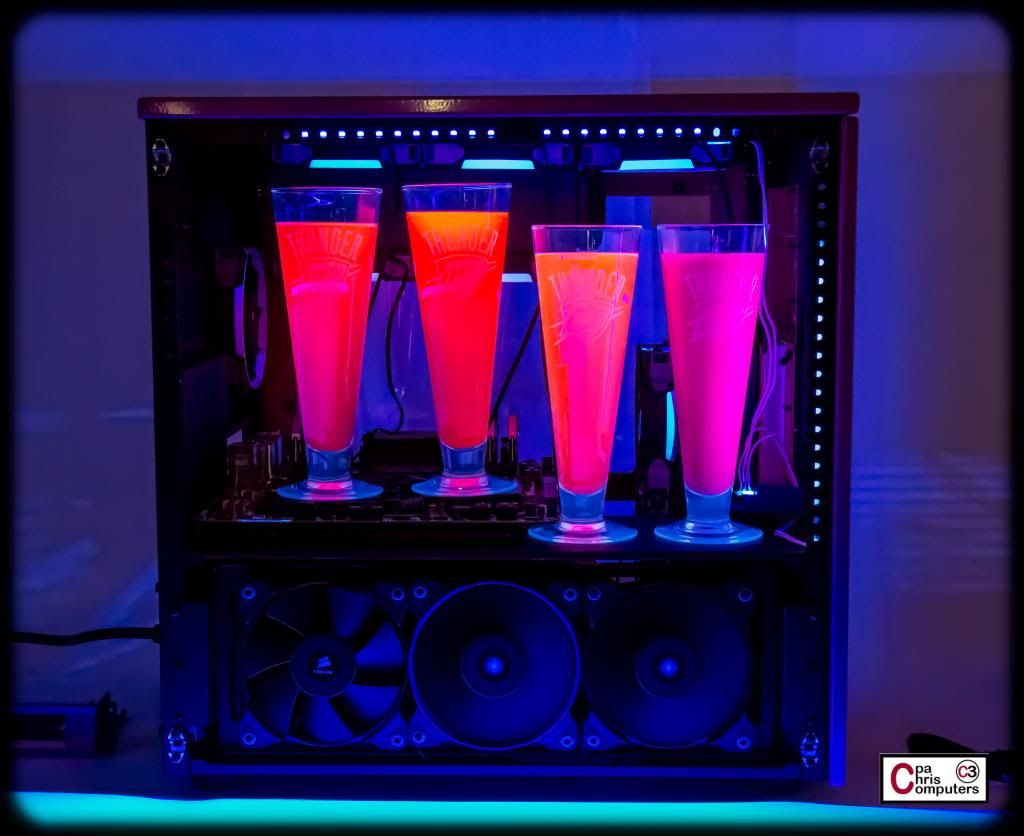
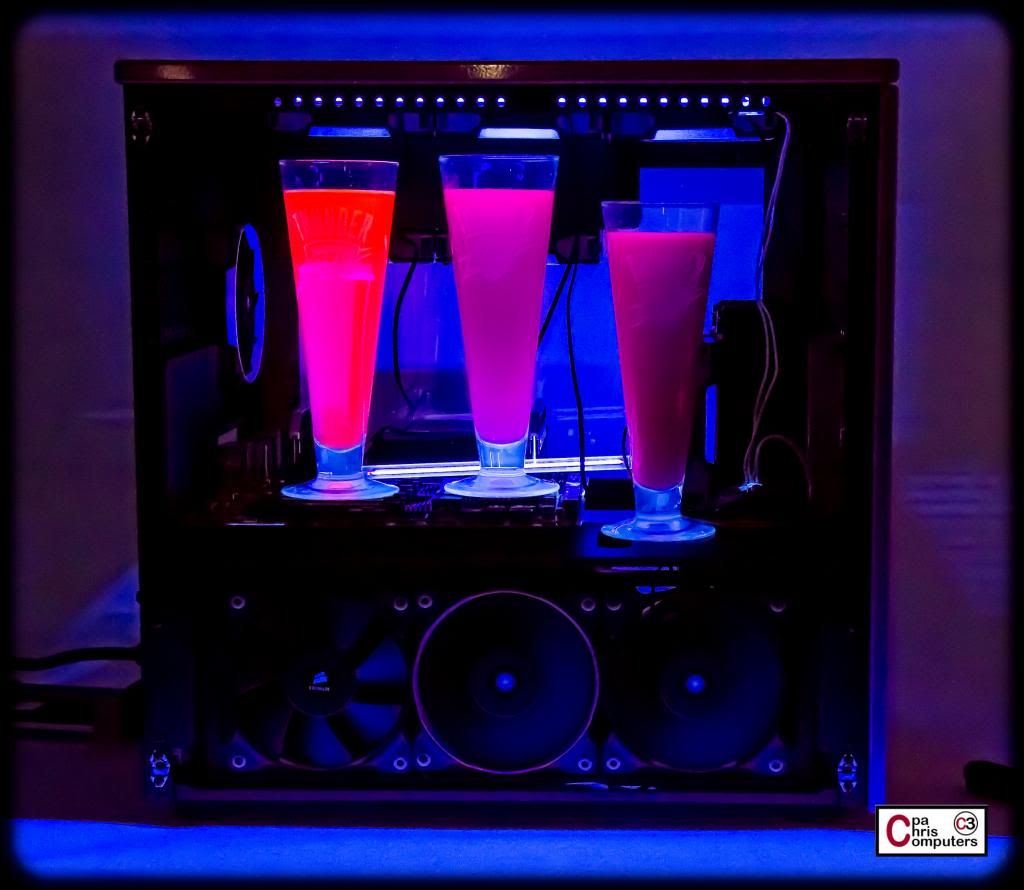
What I decided to do next is see what they looked like under UV light. If you'll recall from earlier posts...I'm planning on having two different lighting schemes inside this build. A white light scheme, and a UV light scheme. Each will operate independently of the other. So to observe the UV reaction, I rustled up a couple of UV cold cathodes, and just set them inside case behind the pilsner glasses....like so:
Below is what they looked like with all the lights turned out...but the UV lights on. #1, #2 and #3 all had a lot of UV reaction and really popped. But they turned a bit toward the orangy/reddish side under UV lights. Still had some overall pink highlights....but also an orangy glow. At first, I was incredibly disappointed in the UV reaction for the pastel....#4. I had emailed Mayhem's to see if the Pink Pastel had a UV reaction, and was told "that it should". Well, the reaction was there...but very small.
I decided that part of why #4 didn't look like the others....was that since it was completely opaque...none of the UV lights were shining through the coolant so that I could see the reaction. In fact, in the picture below, you can see much more UV reaction for #4 on the backside of the glass, where the UV light is shining. For #1, #2, #3....since they are translucent,....it doesn't matter where the source of the UV light is coming from....it illuminates the entire glass. But since #4 is opaque...you really need UV light shining at it from whatever direction it is going to be viewed....to see the reaction.
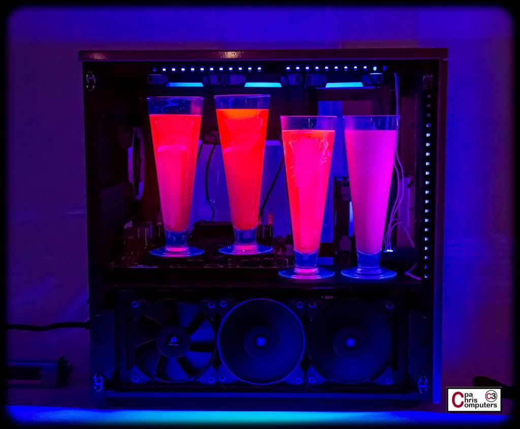
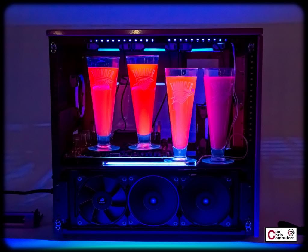
So I made two changes for the picture below. First...I added about 10 drops of the Mayhems Pink UV dye to the Pastel Pink coolant. Secondly, I moved the UV lights to be above the glasses, and over right beside the pastel glass (right hand side of the picture...which is the front of the case). Now....I have the UV light illuminating the portion of the glass that shows in the picture below....
Much better....
You'll notice also that the pastel keeps it's pink color, and doesn't take on an orangy glow. For this one....I added about 10 more drops of the Mayhems Pink UV dye to the pastel glass (#4) to see if it increased the UV effect. Didn't really change it that much...so I think the majority of the previous change was due to the placement of the UV light.
I pulled the UV light from the front of the case and laid it down across the floor right in front of the glasses....and you can see that the front of the #4 glass looks dark again. No UV reaction unless you have UV light shining right at from the direction you are viewing....since it is opaque.
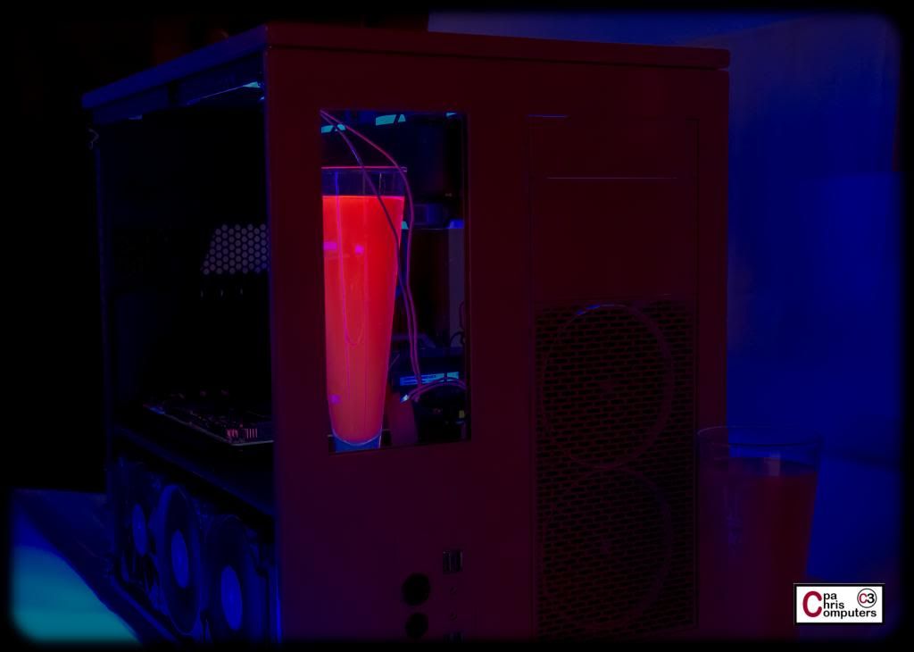
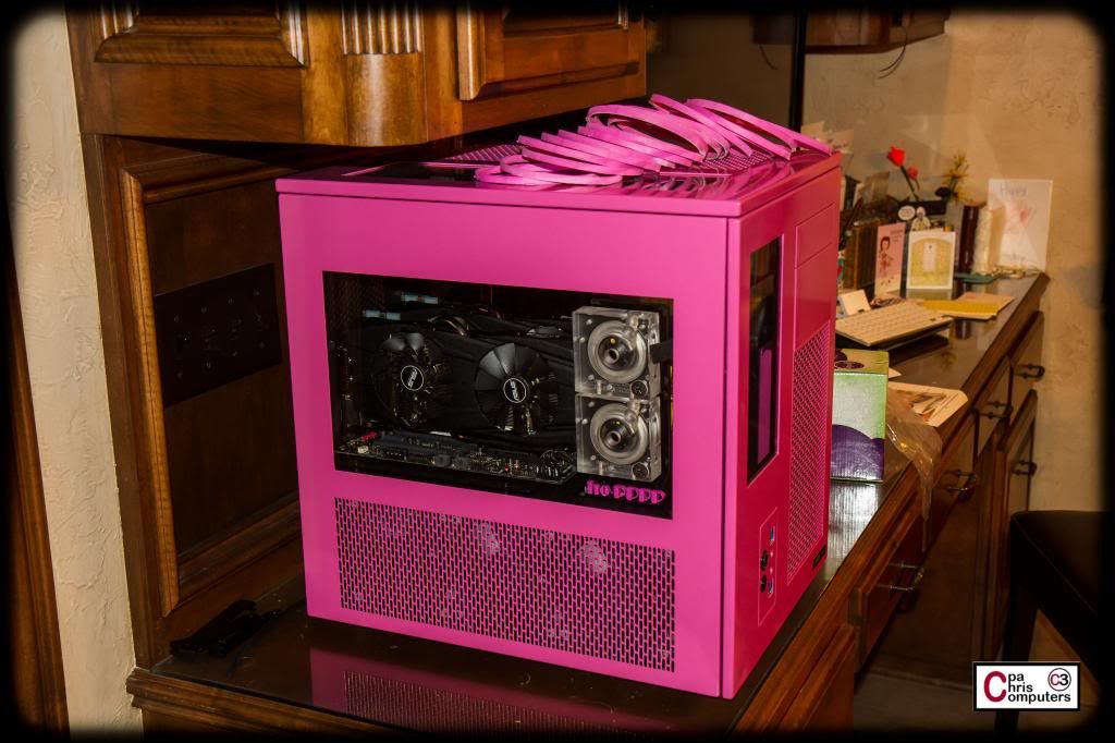
Below is a shot from the front of the case...so you can get a feel for what the reservoir might look like when filled with UV pink coolant and the UV lighting scheme turned on...
As an experiment, I decided to try a significantly reduced concentration of the pastel coolant.....to see if I could get some more light shining through it and illuminating it better. The one on the left is the reduced concentration coolant....and the one on the right is the original batch I mixed up. They look a little different in the normal light. But both still look opaque....
With the UV lights on....I think the reduced concentration one on the left clearly is lighting up better and more evenly than the original batch on the right....
Even when I move the UV light back to the front of the case....much closer to the glass on the right.....the reduced concentration pastel on the left is lighting up nicely.
Let me give you a final couple of shots...and then my thoughts on what I think I've learned.
In these shots, I have, from left to right, 1) Mayhems Pink UV Dye; 2) Reduced concentration Mayhem Pastel Perfect Pink; and 3) Mayhme Pastel Perfect Pink. Lights on....
...and UV lights on.
My take aways are:
1) The Mayhems and Primochill dyes are very similar tint. Either would work....but either is going to take some mixing with another color dye to get a better match for the case.
2) Shouldn't use too much pink....or it starts to turn red.
3) If I want to use the Pastel Perfect Pink with UV lights....I need to reduce the concentration of the coolant so that some light is trasmitted. This improves the UV glow effect immensely.
4) To maximize UV reaction for the pastels...I need lighting coming from whatever angle it is being viewed. This is not necessary for the other non-pastel dyes.
4) With the exception of the pastel coolant....the other dyes turn a bit orangy under UV light.
I'd love to get everyone's thoughts on the following things:
1) Ideas on what color(s) to mix in with pink to match my case better?
2) Which do you like better....the translucent look of the dyes in water....or the opaque look of the pastel coolant?
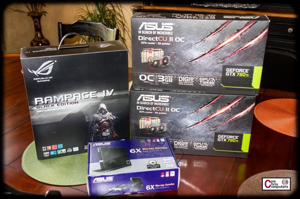
I didn't have time to open it before church tonight....but I left Taylor and Tebow in charge and told them to guard it with their lives...
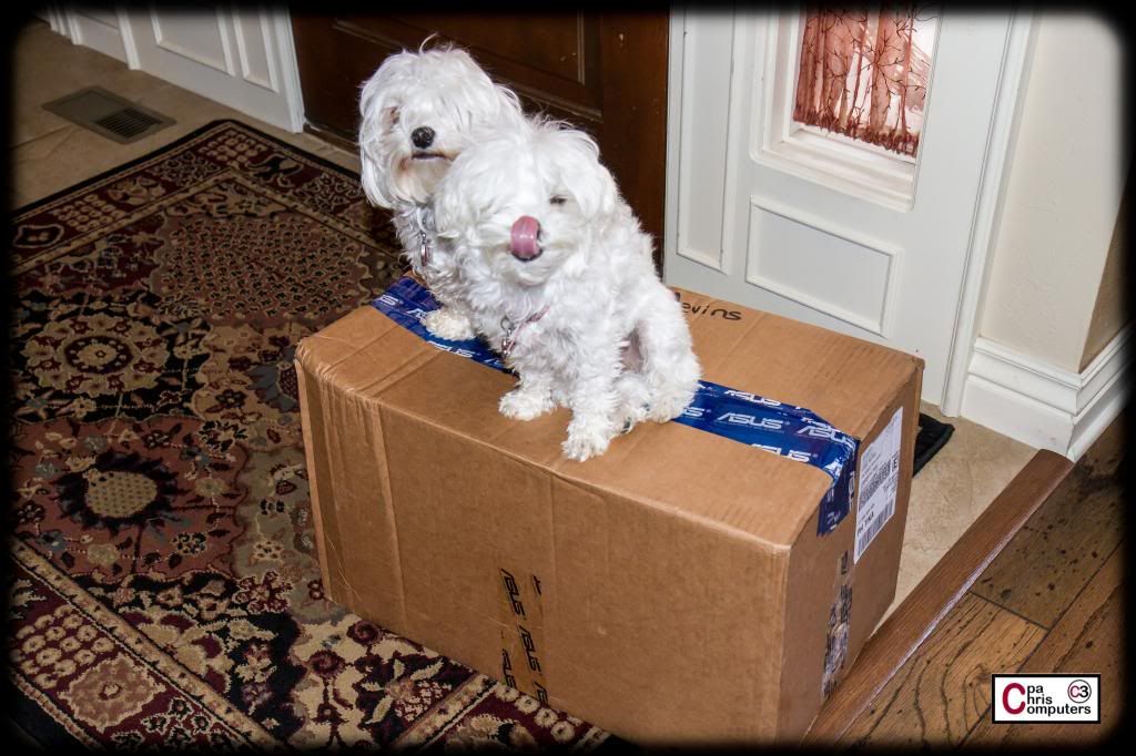
Fairly obvious choices.
That's a lot of ASUS goodness sitting on the table right there. I'll have time to open them up and take some good hardware shots tomorrow and Saturday.

for farmville and scentsy orders.. hang on im going to go kill myself..
lol.....you forgot about Pinterest!
yep. /killsself
not sure if I understand sponsorship "giveaways".. they should have givin you a pair of 750ti.. but they give you a setup where you could max any game currently on the market (@4k)
but, good for you im just jelly
Don't worry....I'll put it through it's gaming paces also....before being released into the field to complete it's Scentsy work.
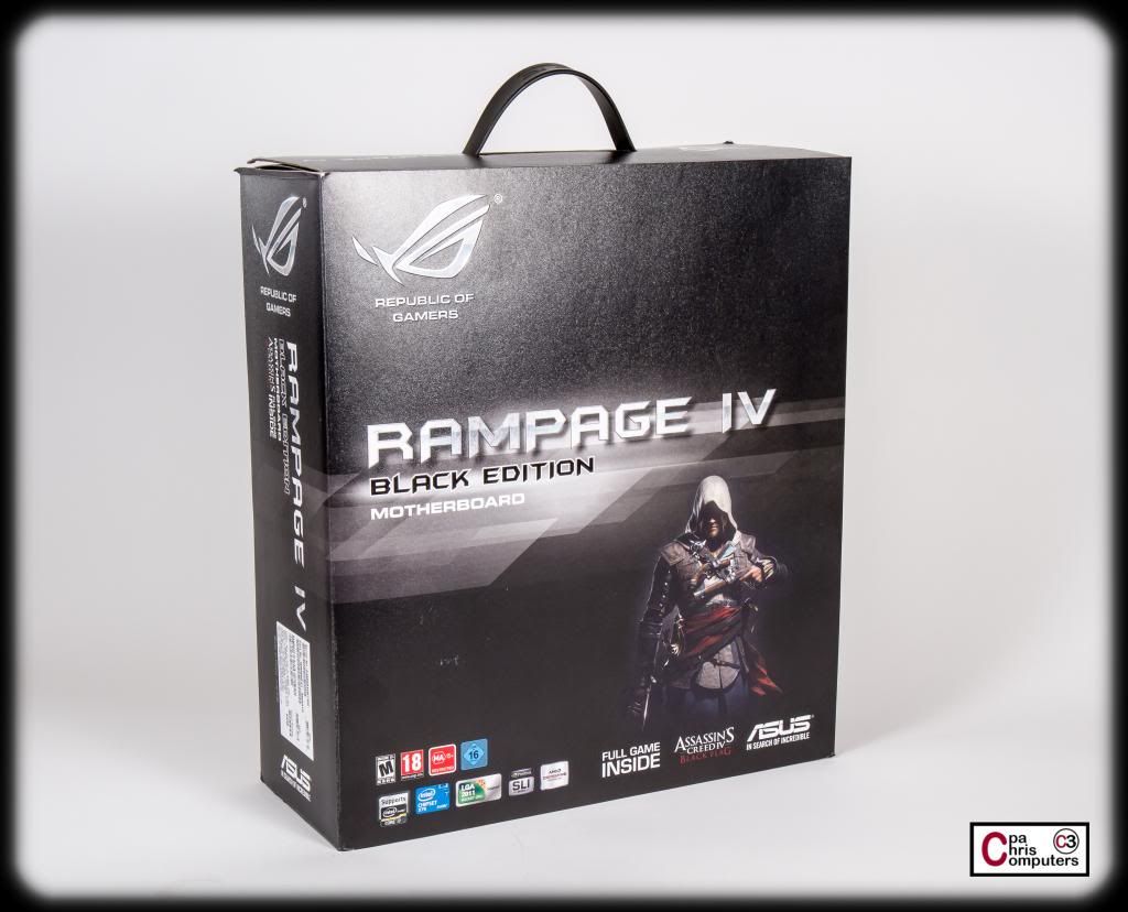
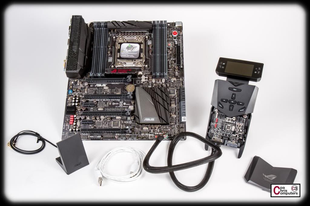
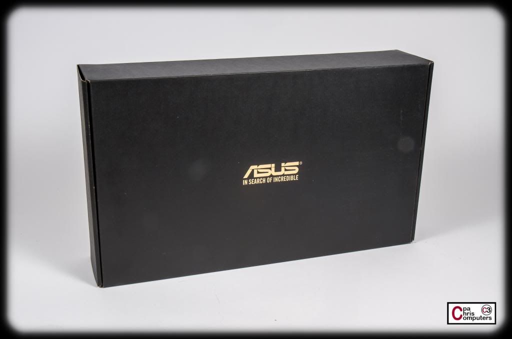
This first group of pictures is just kind of an unboxing series of pictures for the RIVE BE motherboard, and is intended to show off the packaging and all of the accessories that come with the motherboard.
For a primarily black motherboard.....you clearly need a primarily black box. Check.
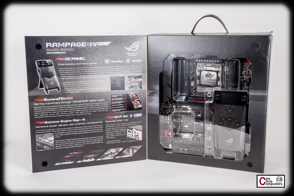
And like a lot of motherboard packages, there is a flap that opens to reveal a clear view into the box inside to show off the motherboard. Flap also serves as space for additional marketing yada yada to be printed on the inside of the flap...
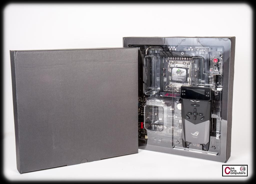
There are two boxes inside the large box. The solid cover one on the left holds the accessories, and the clear cover one on the right holds the board itself. And that strange little Star Wars-esque thingy. What is that thing? Let's take a closer look....
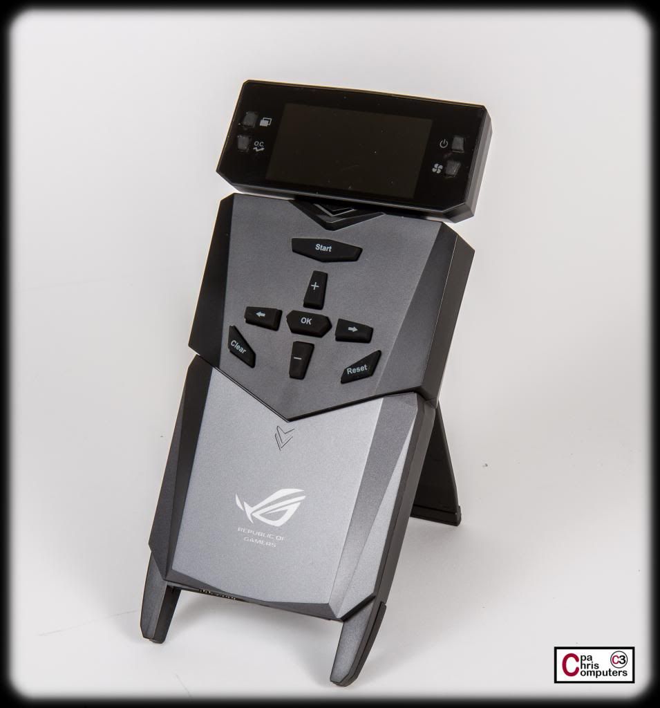
The Star Wars looking thingy is what ASUS calls the Overclocking Command Center.
You plug this thing directly into the motherboard, and it allows you to monitor AND CHANGE voltages at the hardware-level. You can also adjust overclock settings and fan speeds directly from the device. It sounds like it could be very useful while setting up your overclocks. I'm intrigued, and you will definitely see some more pictures and/or video of thing in action....
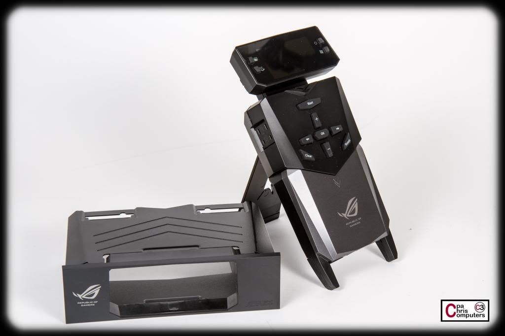
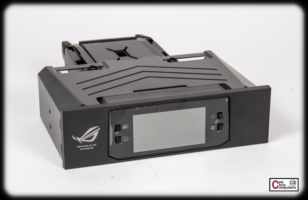
it even comes with this 5.25 inch bay adapter.....
...which allows you to swivel the LED head and slide it into this mount, and install it in your case. I probably won't install it in the case just because I want to keep the front of the computer as clean as possible. I'll already have an Aquaero on the front panel.
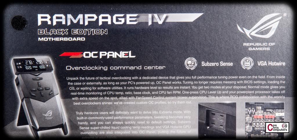
Here is the marketing gib gab related to the overclocking panel from the box....
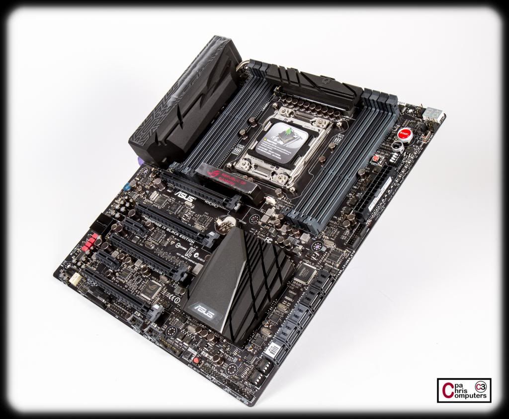
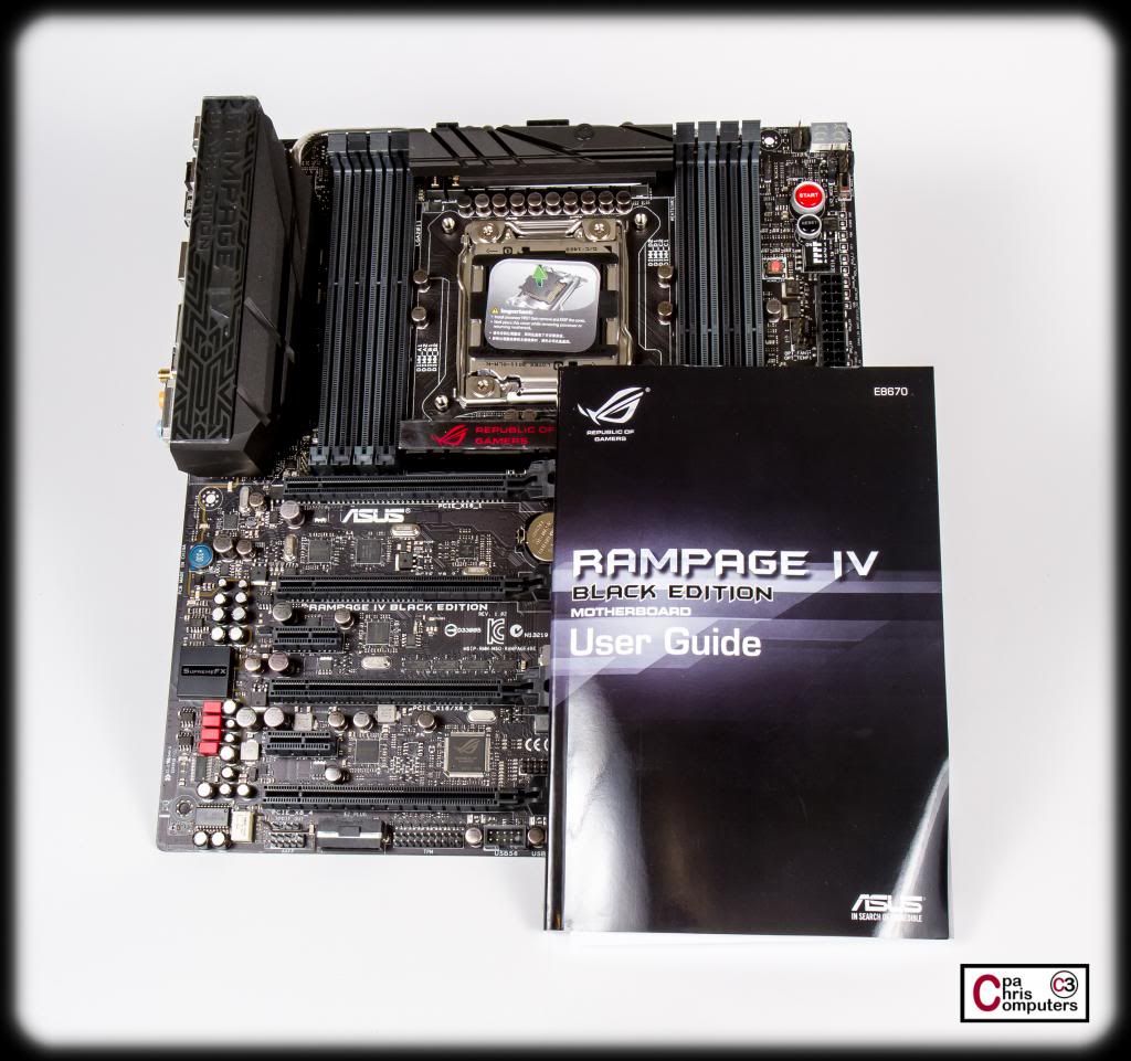
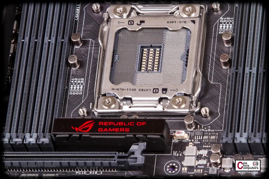
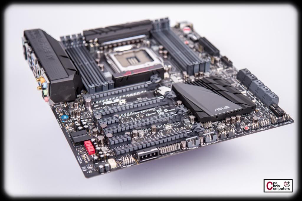
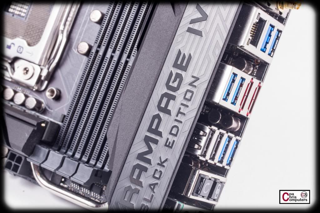
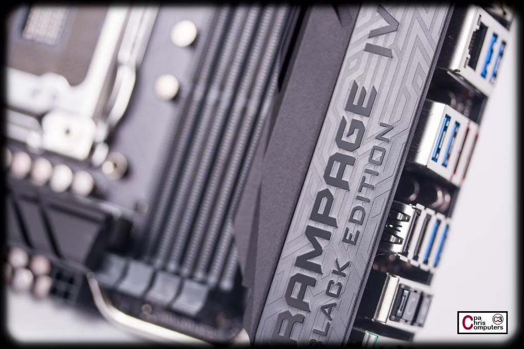
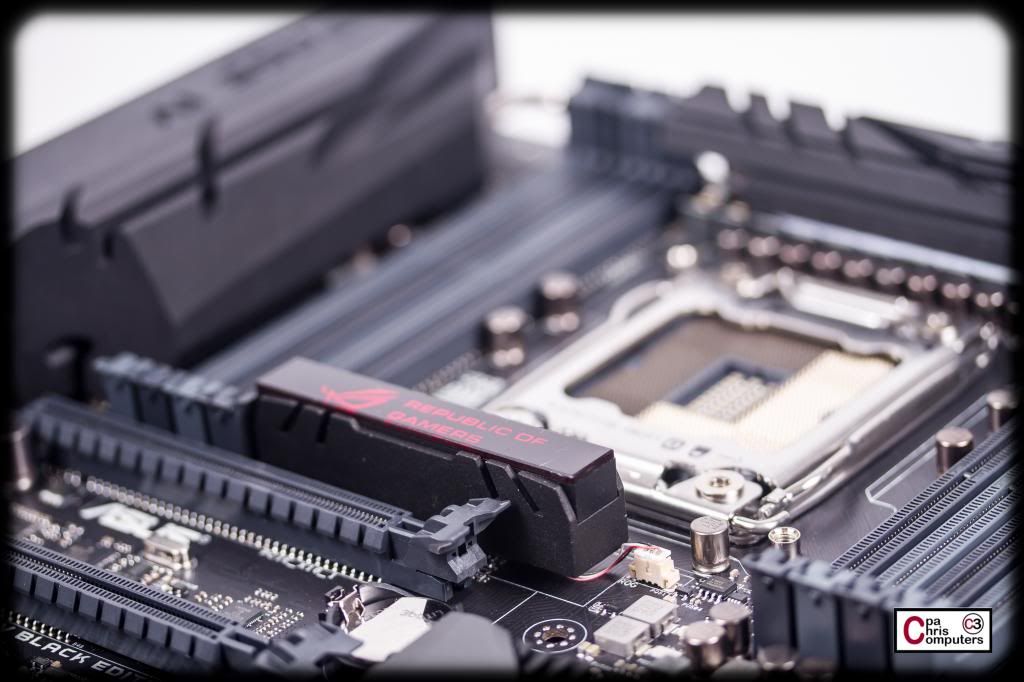
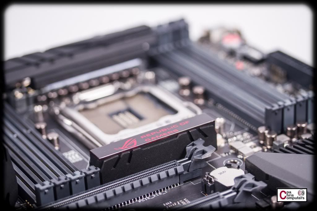
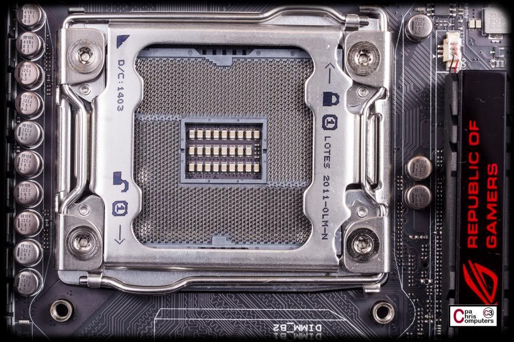
Ahhhhhhhhh. The board itself. I've always found the RIVE BE beautiful, and it's one of the main reasons I approached ASUS about partnering with me on this build. I just love how tough, black and powerful this thing looks. And with me going for a primarily black interior theme....and wanting an X79 board again.....it really just made the most sense to go this route.
The heatsinks won't be on there after I block the board....but even the heatsinks are well done. I'm going to try and find a way to leave the I/O cover that is incorporated into the heat pipe. Probably have to cut the heatpipe....but no big deal. The I/O cover itself is a very nice touch. I've spent a fair amount of time on some prior builds trying to cover up the back of what is usually just some shiny metallic boxes on the I/O panel. This is a far more elegant solution. Nice touch ASUS.
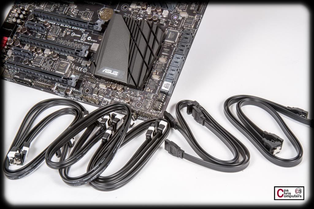
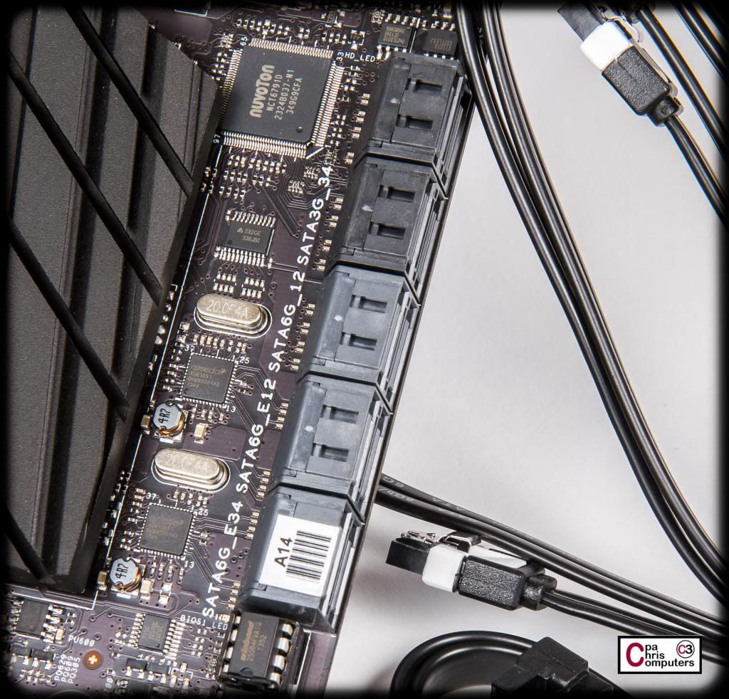
Enough of the board for now. I need to take off some of the protective stickers, and take some real glamour shots. These shots are just to show what was in the box really. So lets move on to the accessories included. There are 10 SATA cables included. The ones with the white band on the tip are the SATA3 cables, and the all black ones are the SATA2 cables. 1/2 of the cables are 90 degree angle ends, and the other 1/2 are straight ends. That should keep it easy to plug and unplug when they are stacked on top of each other. Nice touch ASUS.
....and 10 cables matches perfectly with the 10 SATA ports on the board. The grey ones are SATA3 and the black ones are SATA2.
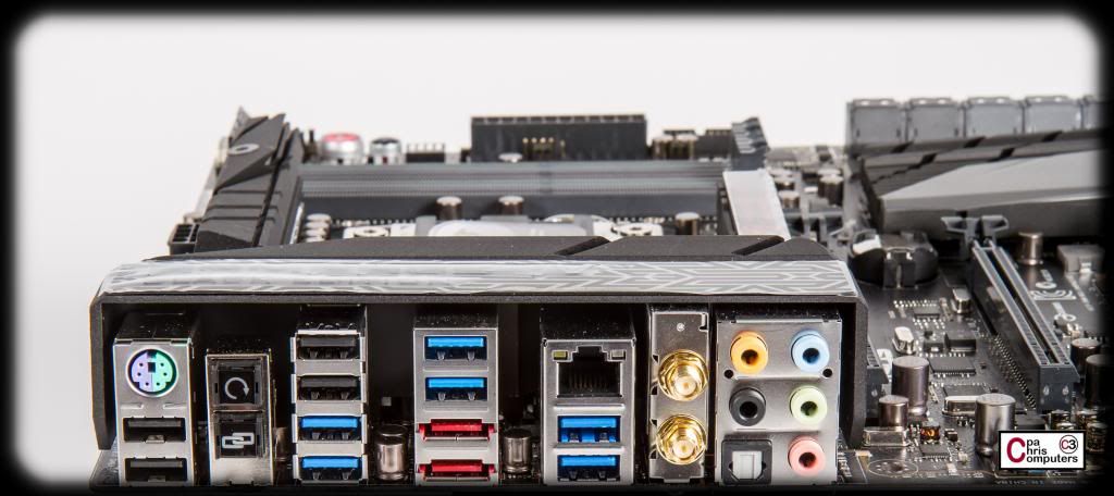
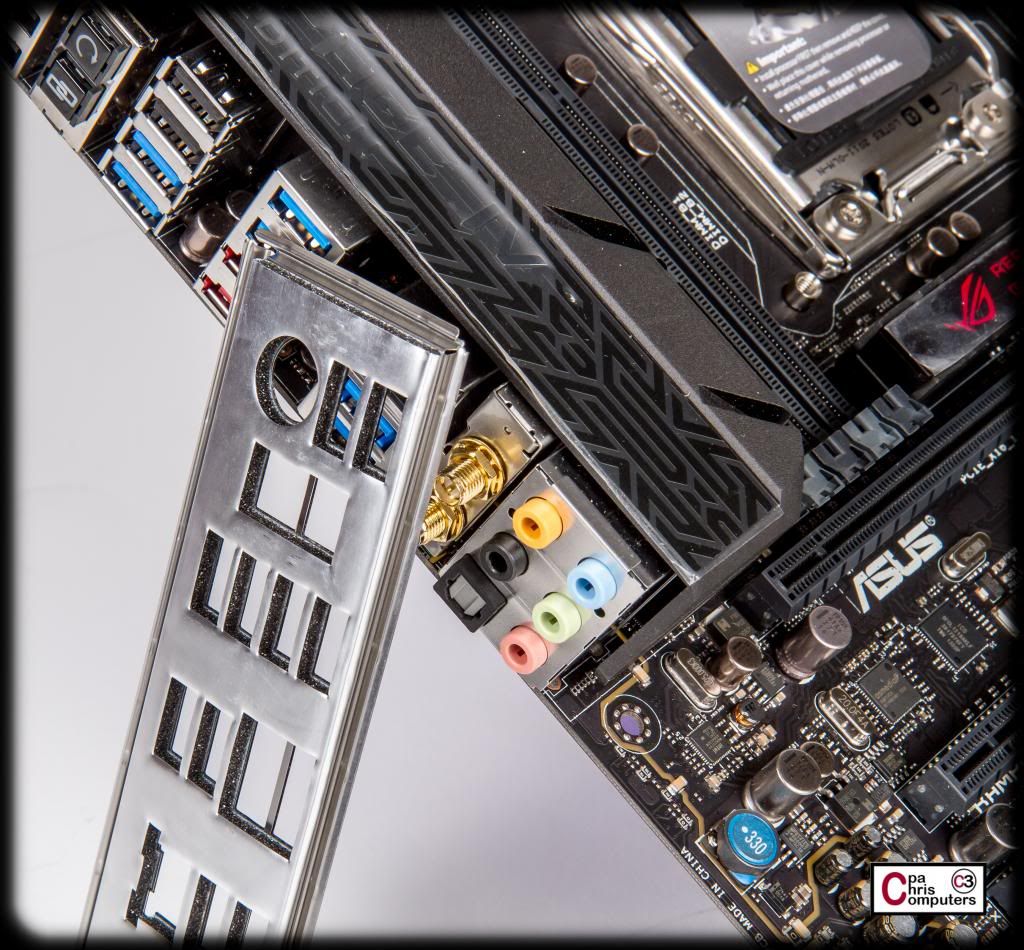
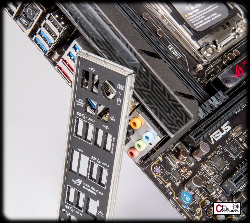
Check out the I/O shield that I have leaned up against the I/O panel. That's the backside of it showing. You'll notice there is a rather thick layer of foam with a metallic type backing that surrounds all of the cut-outs.
Here is the front side of the I/O shield, and if you look at the cut-outs closely, you can see the thick foam extending behind each cut-out. This foam takes up the empty space that normally exists in most motherboards between the I/O shield and the I/O panel itself. A very nice touch ASUS.
Here are some of the other cables that come in the box. From left to right along the bottom of the board....first up is the WIFI antennae. Now...I will always end up running CAT6 cable to the box when it's in it's final location, because almost every room in my house is wired. But....I can't tell you how nice it will be to have WIFI access built into the board so that is can be connected while it's still being moved around a lot and worked on in every room of the house.
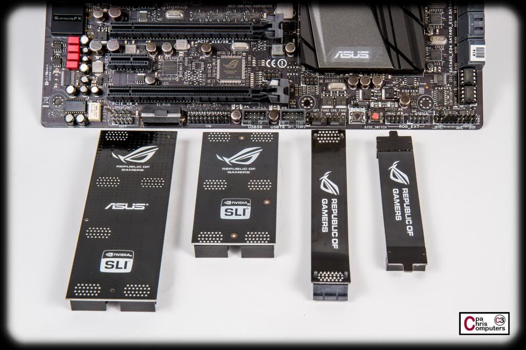
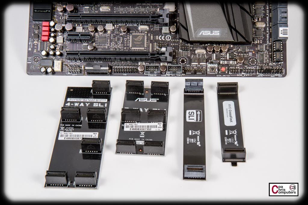
It comes with all the SLI connectors you might possibly need....
This is a pretty neat idea. For all the little dupont style connectors, ASUS has created a single plug that can be removed from the motherboard and all of the little connectors come off with it. This will save a ton of time for those of you with fat little fingers like mine and have trouble with the 2pin dupont style connectors. Nice touch ASUS.
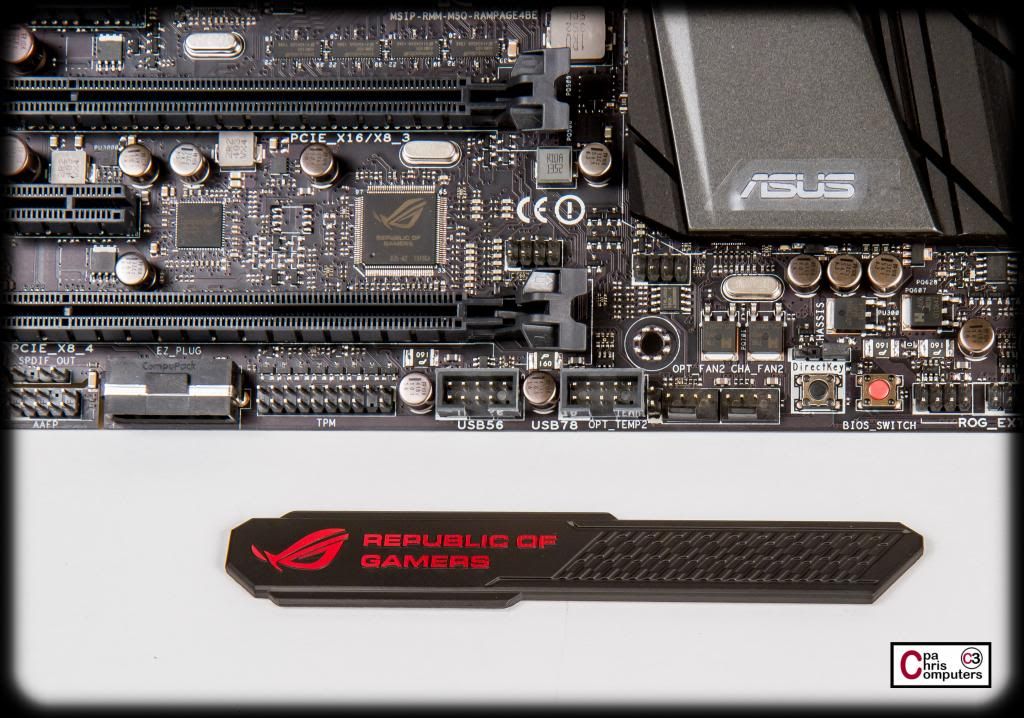
Sticker for a case badge? Not on a $500 motherboard. This is a hefty magnetic case badge. Nice touch ASUS.
I haven't gone through the User Manual yet.....but I gave it the "bulk test" review....and it passed. It's thick. Nice cover too!
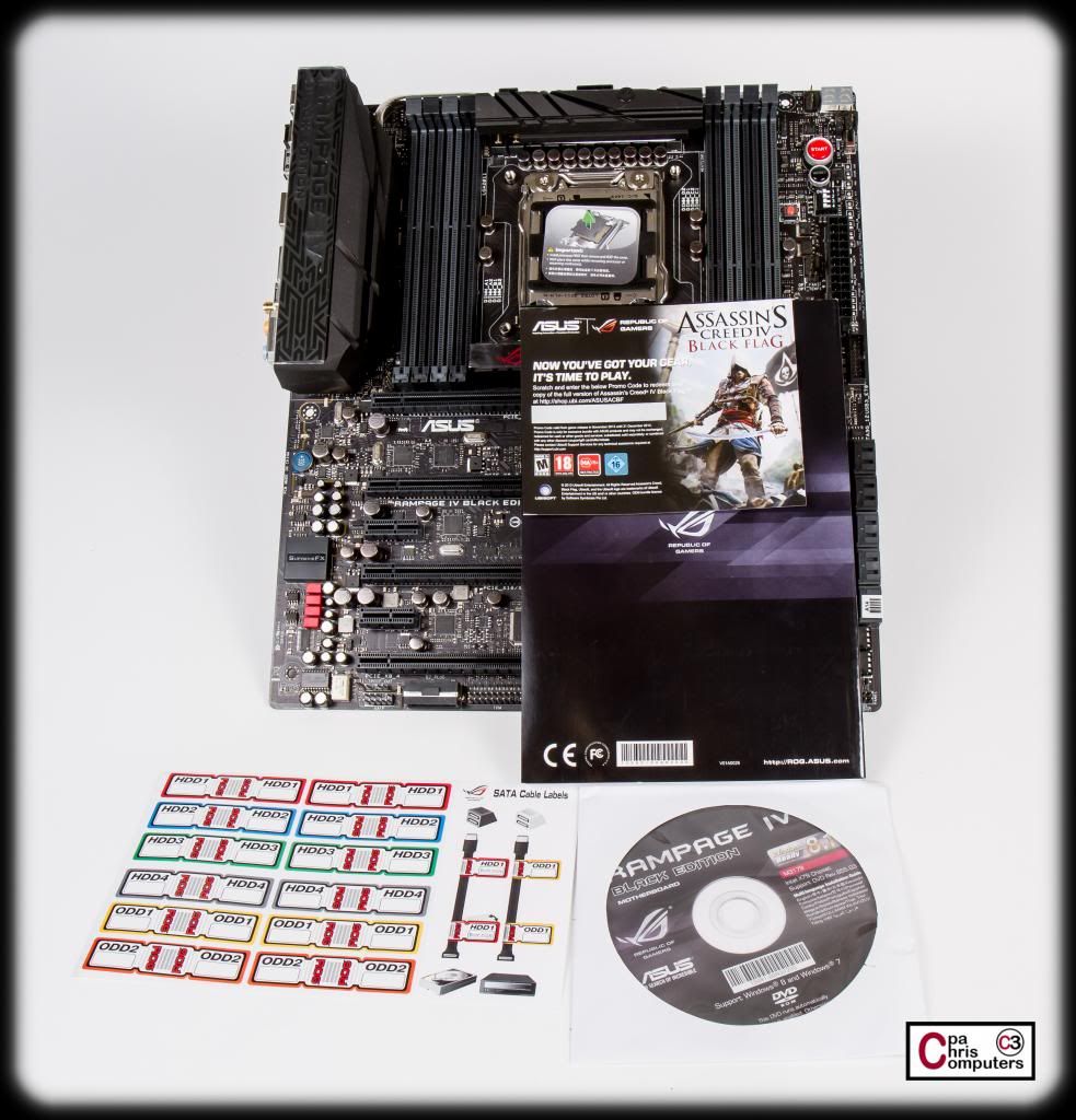
Now....I don't know how many people spend $500 on a beautiful motherboard....and then use these atrocious stickers on their HDD cabling.....but maybe some do.[Seinfeld Voice] Not that there's anything wrong with that! A DVD of drivers and user manual, along with a coupon for a copy of Assassin's Creed Black Flag....round out the accessory package.
Very pleased with the initial run-through. Now I'm going to take off some of the protective film and get out my macro lens. The board has so many features on it that I'll take some close-ups of some of the neat stuff it has on it. More soon.....
keep those awesome shots comin'
"Study hard my young friend"[/B].
---------------------------------------
Woody: It's not a laser! It's a... [sighs in frustration]
This group of shots is intended to highlight some of the features of the board. I basically got out the user manual and my camera...and snapped a shot of everything as I went through the manual and learned about all the "stuff" on the board. Some really neat features packed in here.
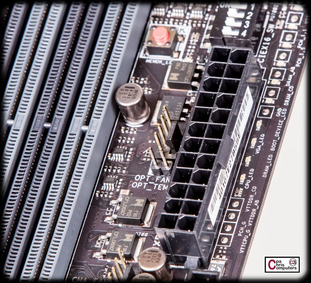
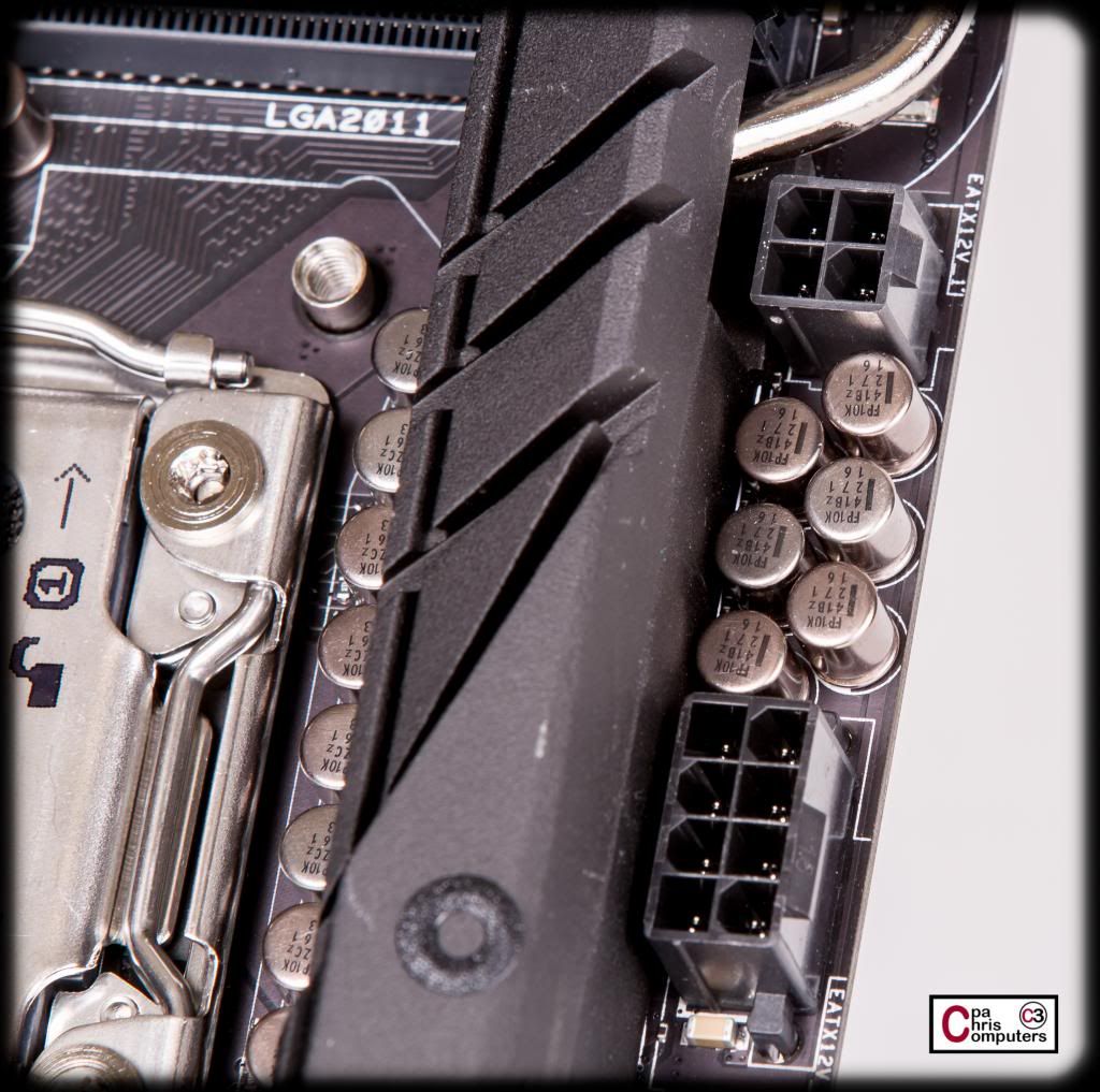
First...I'll show the power connectors. Of course there is a 24 pin. It's situated in the normal spot on the right edge of the board. I think a nice tweak here would be to rotate it so that it faces out from the board instead of straight up. Some companies are starting to do this now...and it really makes sense to me.
On top of the board is a 4 pin and an 8 pin power connectors....
...and on the bottom of the board is a 4 pin molex style connector. The manual says it should be used when running multiple graphics cards. Check. I'll be powering this baby up on all possible fronts.
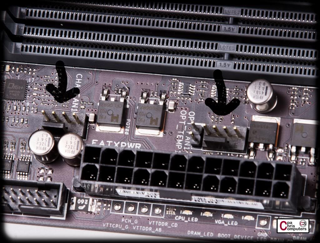
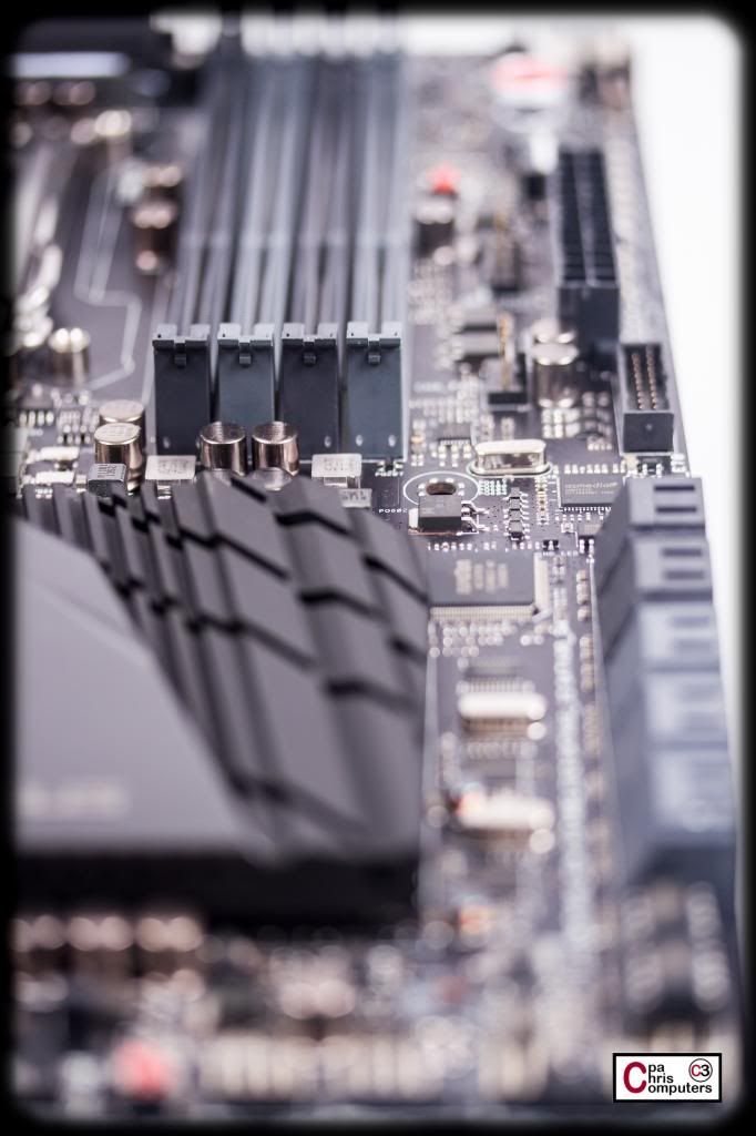
The board has NUMEROUS fan options. They are all PWM compatible also, which is a nice touch. The first is up on the top of the board above the CPU socket....
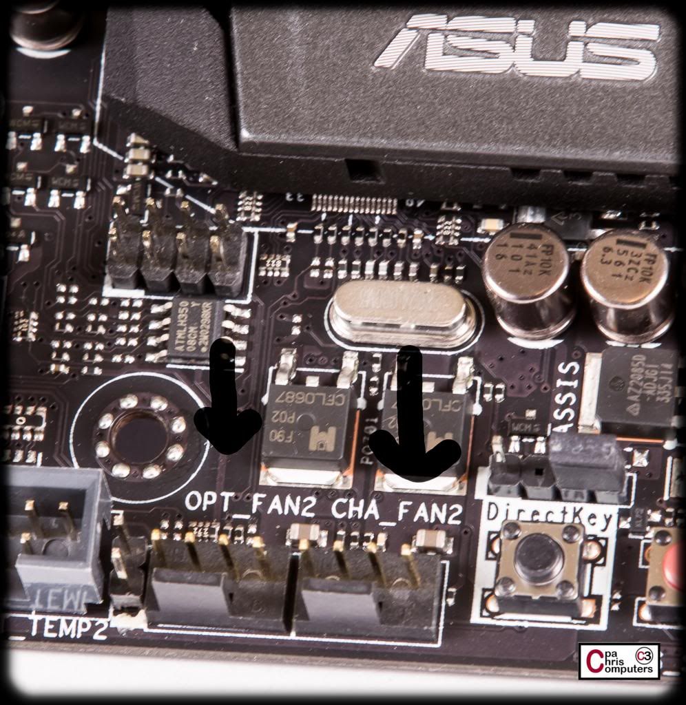
There are two more on the top/right corner of the board....
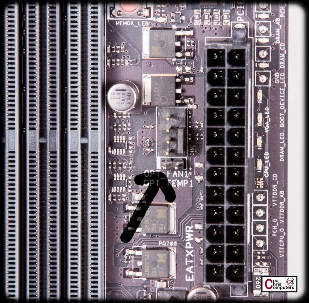
....two more right behind the 24 pin socket....
....and two more on the bottom edge of the board. That's 7 total. That's a lot. Nice touch ASUS.
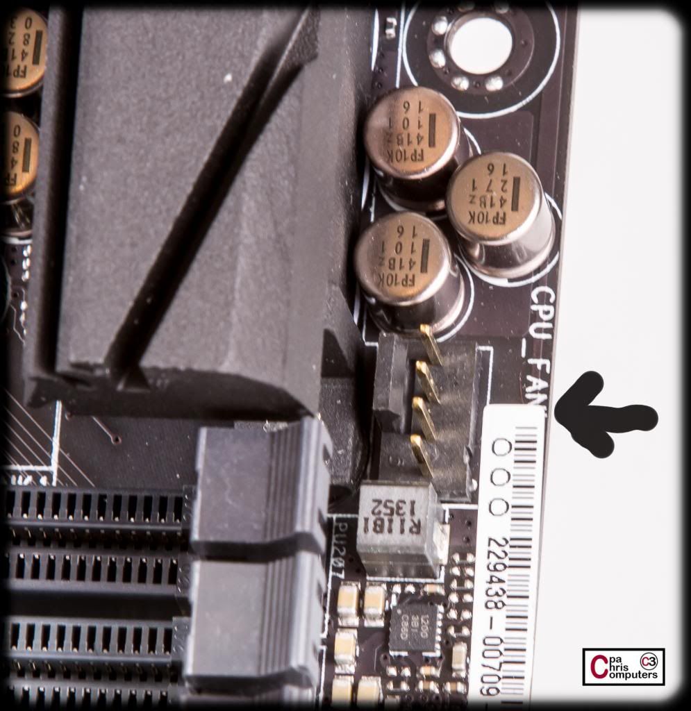
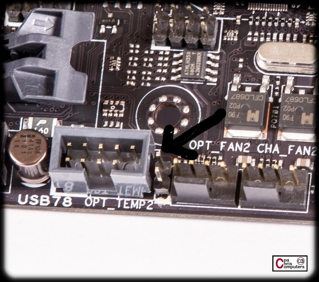
Another really nice touch is adding thermal sensor connections right on the motherboard itself. There are three of them. The first is up in the top/right corner...
The second is behind the 24 pin connection....
..and the third is at the bottom of the board between the USB and fan connections.
I think that these thermal sensor connections would be extremely useful for someone who is air cooling and driving their fans from the motherboard fan connections I showed previously. For water coolers....you probably will want to control your pumps AND fans based on temperature readings....and I wouldn't recommend trying to power your pump from one of the motherboard fan connections. So I think these will be useful mostly for air coolers....not water coolers. But it's still a real nice touch. I wonder if the thermal sensor readings become available to Aida64....and thus...available to something like an Aquaero. I'll try that once I hook up my Aquaero and get things running.
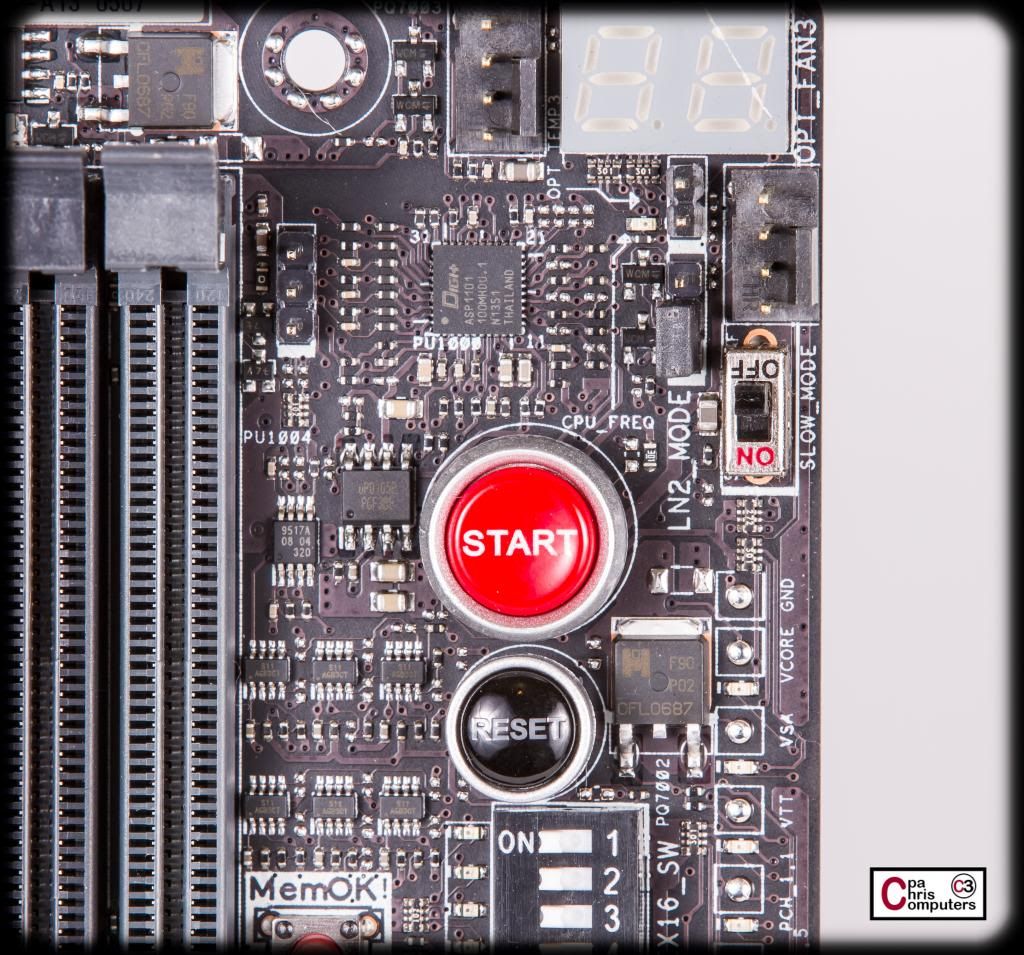
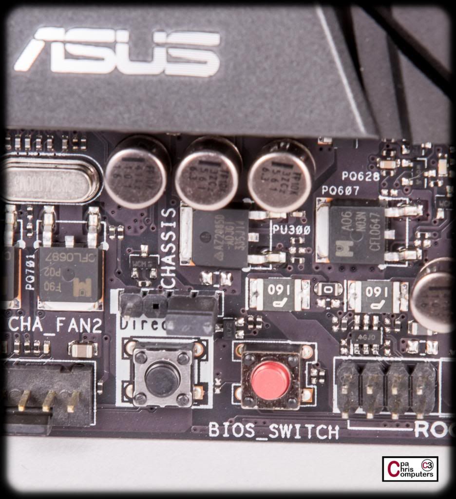
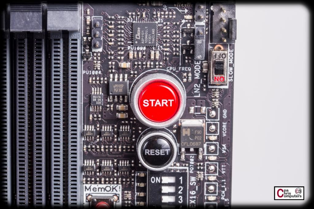
The "start" and "reset" buttons are in an easy to access location. One of the things I don't really like about my Asrock Extreme11 (but I love the board overall!) is the location of these buttons are on the very bottom edge of the board. It makes them very difficult to access in any circumstance....and almost impossible to access when you have something in the bottom PCIe slot.
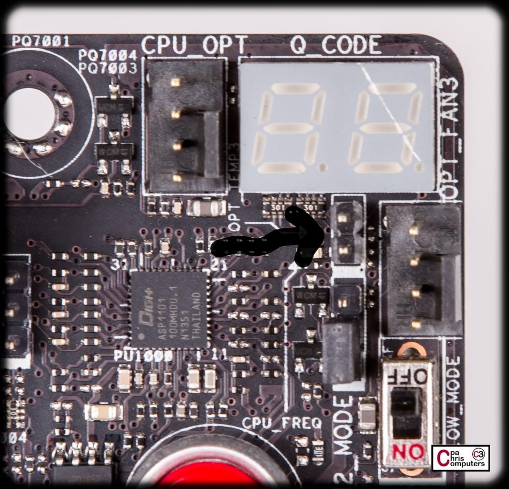
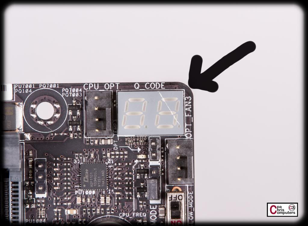
Very similar to the "start" button....the debug LED's are in a very easy to see/reach location on this board. Mine has a scratch across the LED....but I'm hoping it is a cosmetic defect only. If so....not that big a deal.. I'll know once I power it up.
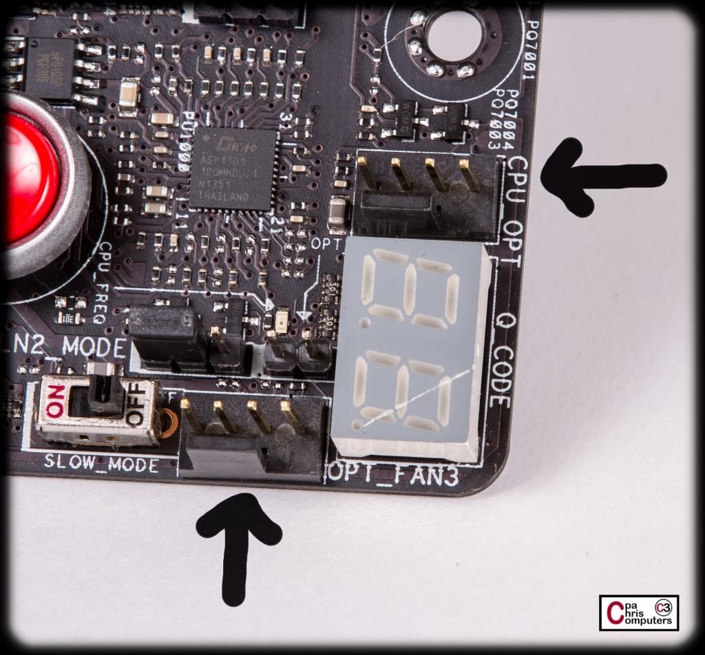
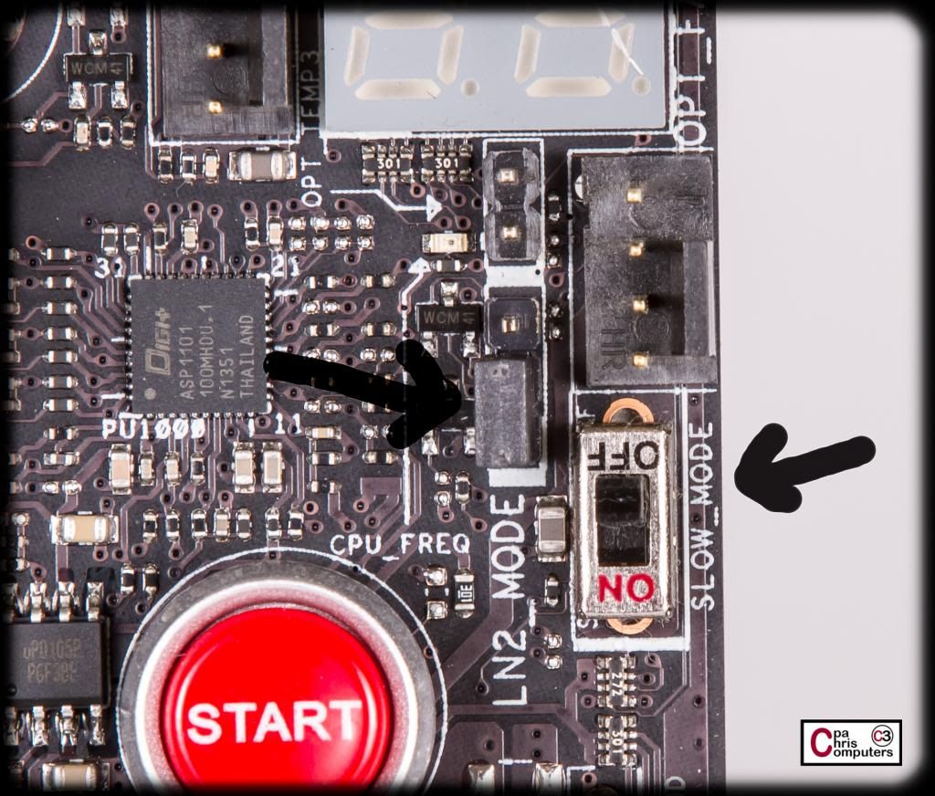
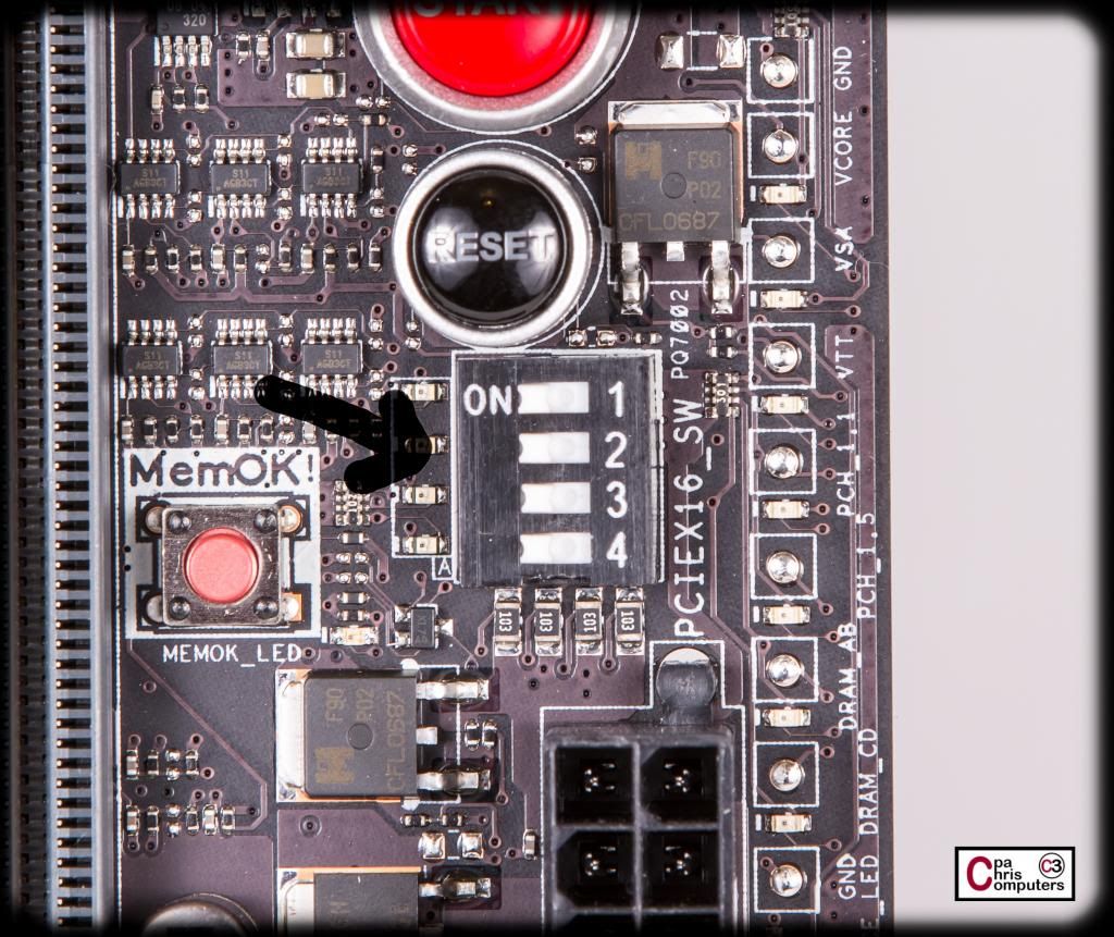
These next two features are kind of cool. Both are related to our LN2 brothers out there....that are trying to boot this board cold. The left arrow points to a jumper switch where, when activated, optimizes the board to remedy the cold-boot bug during POST at extremely low temperatures. The right arrow points to a "slow mode" switch. Flipping the switch down clocks the CPU instantaneously, which allows LN2 users to boot at non optimal temperatures. Neat stuff. But since this will be a water cooled build...I won't use these two features.
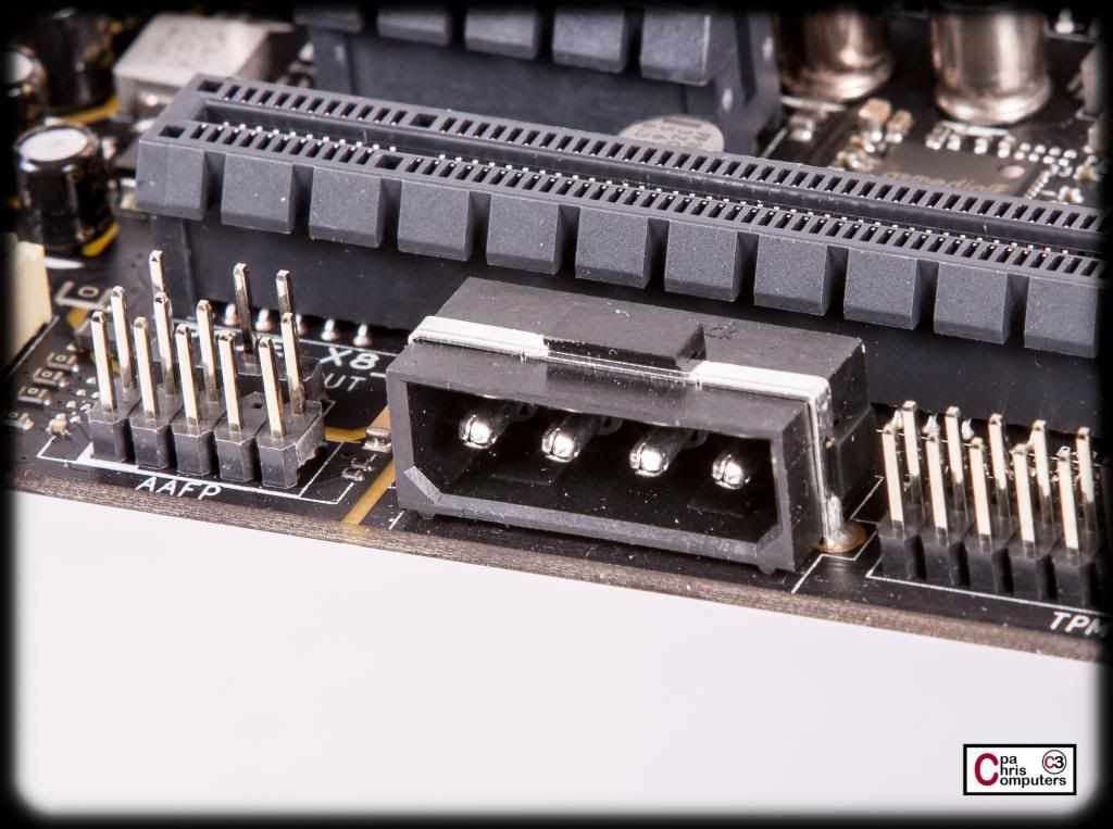
Here's a neat little switch. This one lets you enable or disable the corresponding PCIe x16 slots. So...if you had a problem with one of your cards...you could use this slide switch to find out the faulty one without removing the card itself. Very nice...if they all happen to be hooked up to a water cooling loop. Nice touch ASUS.
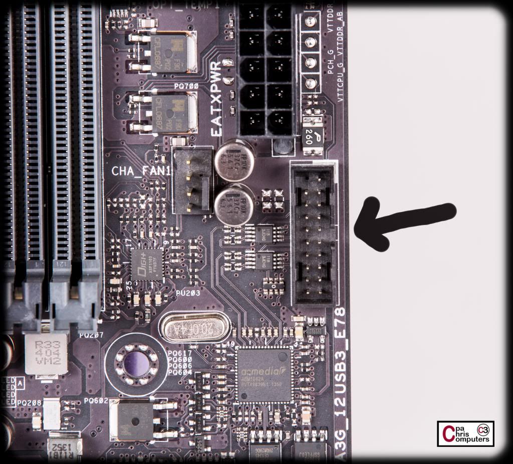
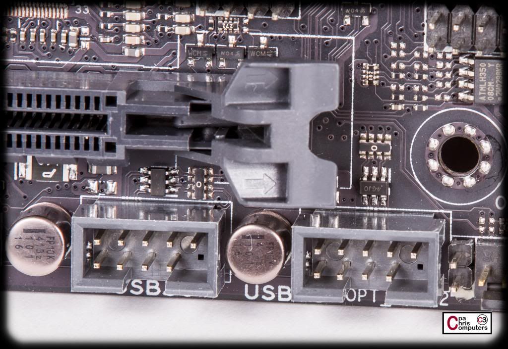
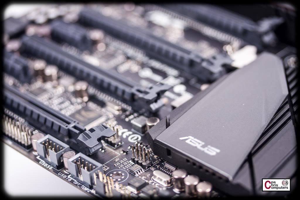
USB 3.0 header. Wish there were two of these....
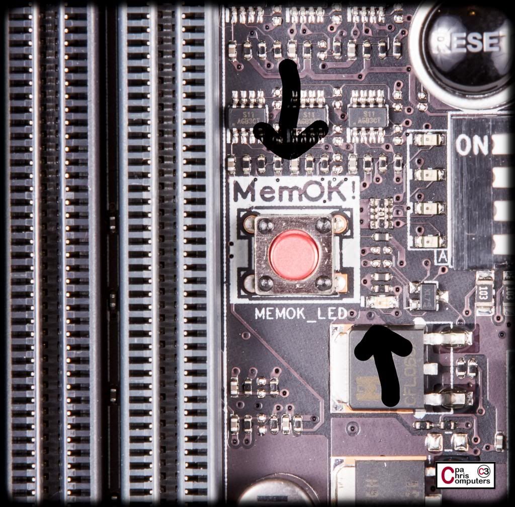
Here's another nifty little feature. There is a little LED (right arrow) that lights up if memory issues are causing your boot to fail. That alone is nice. But the button to the left (left arrow) is even neater. If you press it, the sytem initiates a memory tuning process where the system loads and tests failsafe memory settings, until it can successfully boot. Very nice touch ASUS.
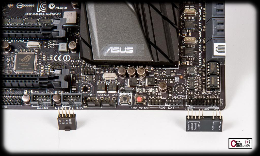
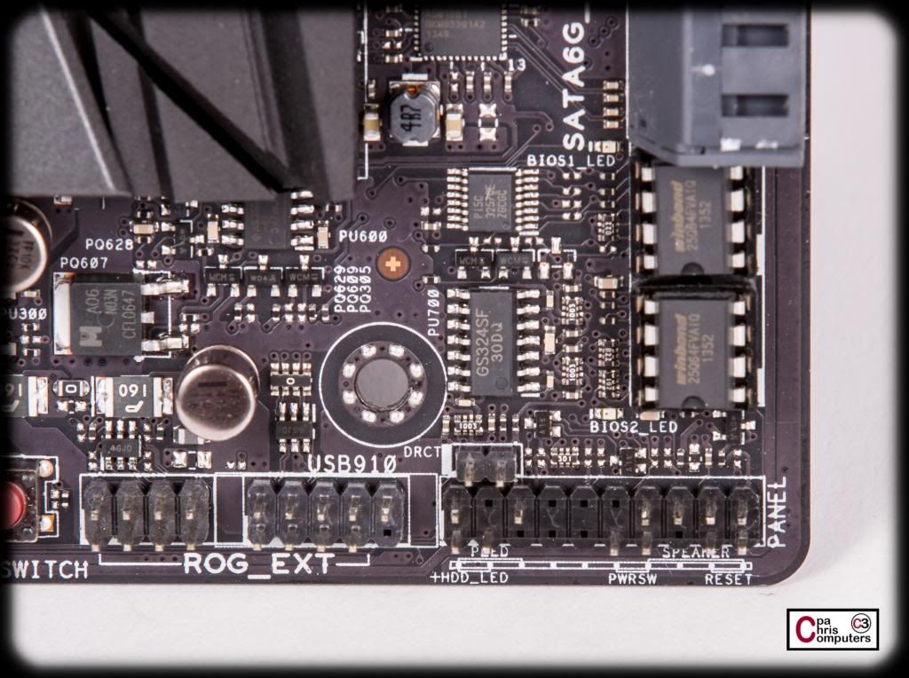
Down in the lower right corner of the board, you'll find the ROG Extension connection, and the front panel connections for the power, reset, HDD LED, etc. If you don't have the ROG overclocking panel plugged into the ROG extension....the right portion of it becomes a USB 2.0 connection. Nice touch ASUS.
Two very cool features in this picture. On the left, you'll see a "DirectKey" button. When you press this button, it allows your system to go to the BIOS setup program without having to press the DEL key during POST. Hello! I'll definitely use this feature. Not available on my Asrock board. Me likey. To the right of this button is the BIOS Switch button. This board allows you to have two different BIOS loaded. When you press this button, it switches to the other BIOS. Hello! I can definitely find use for this feature also. My Asrock board allows me to save 3 different BIOS settings....but I have to reboot and enter BIOS setup to activate them. Not having to enter BIOS setup will be sweet. Very nice touch ASUS.
Two more USB 2.0 connections at the bottom of the board....
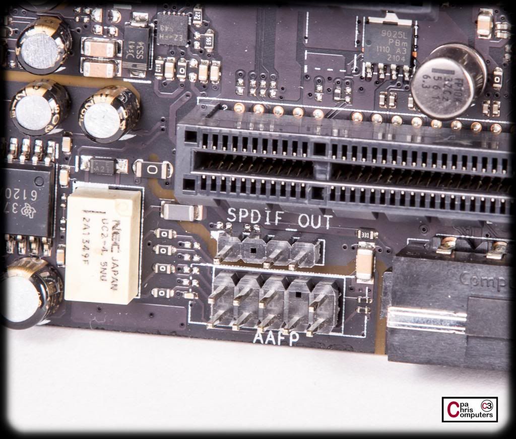
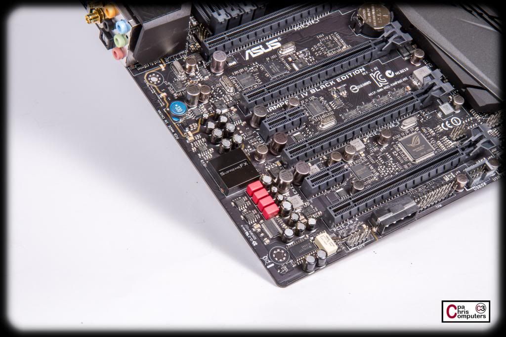
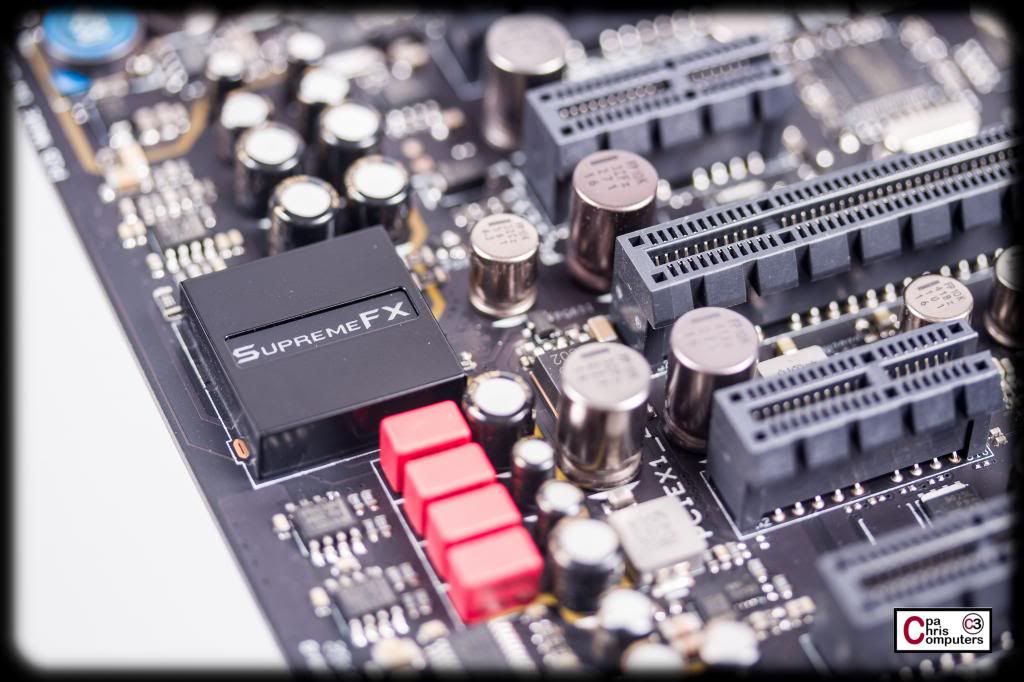
Front panel audio connections....
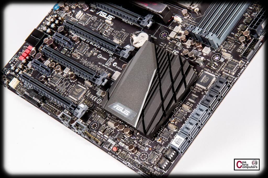
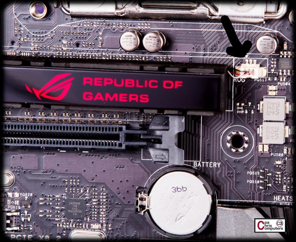
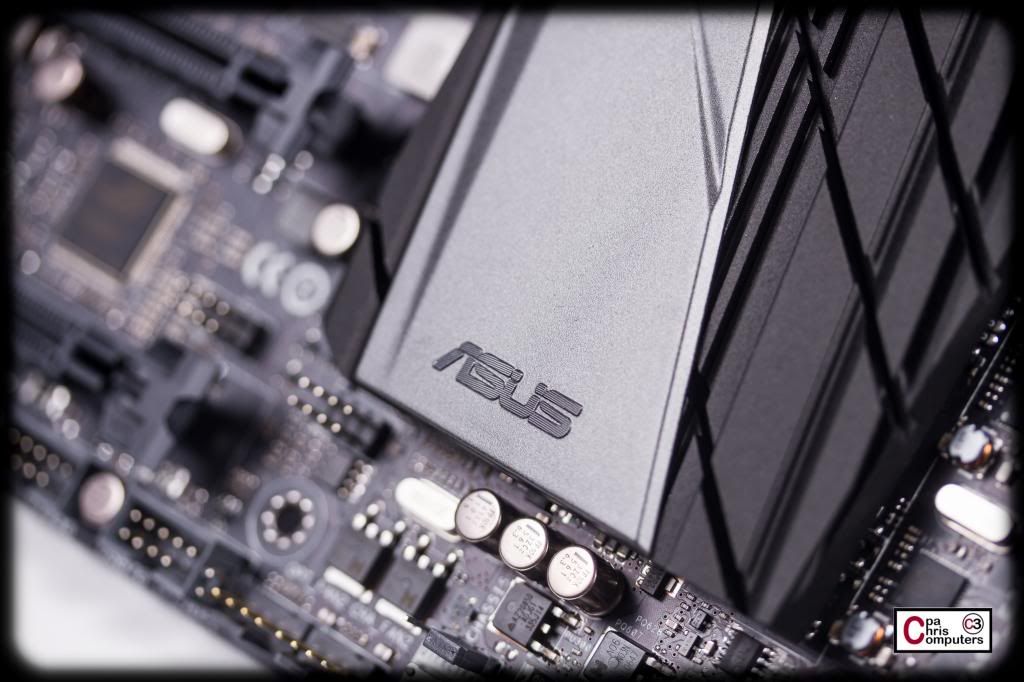
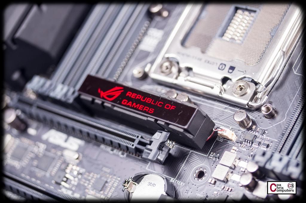
And in the center you'll find the CMOS battery....as well as what appears to be a little power connection for an LED inside the ROG logo in the middle of the board.
Overall...I find the feature set on this board amazing. This is actually my first ASUS board. I've owned primarily Gigabyte and Asrock in the past. Features are way cool on this board. Can't wait to fire it up and try them all out.
This board has a ton of features that my Asrock Extreme11 doesn't have.....but it's also missing some things I'd love to see on it. If I were in charge of creating the perfect motherboard, here is what I would do. I would start with this board. This board, because it really has most of what any user could ever want. I'd start with this board, the ASUS RIVE BE....and here are the changes I'd make:'
- add 2 PLX chips so that you can have 4x SLI with 16x lanes for each card
- add an LSI 2308 chip for expansion of SATA connections
- add a second USB 3.0 header
- rotate the 24 pin connection so it faces the edge of the board
There you go. The perfect board.
But this one appears to be pretty darn close anyway. Next up are the glamour shots. I've already taken them......they are in post processing now. More soon!
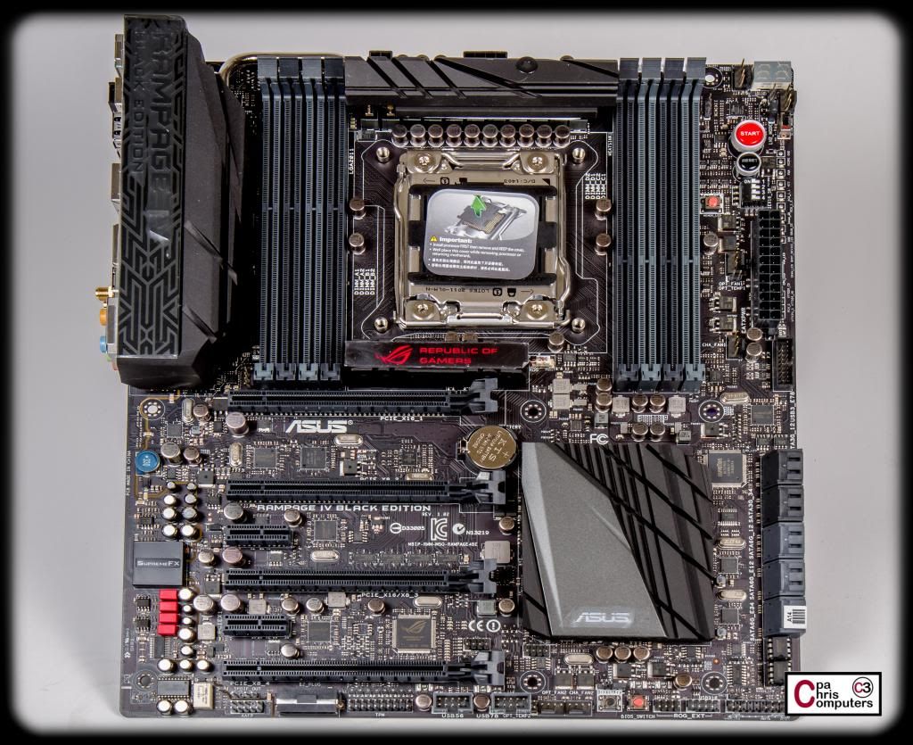
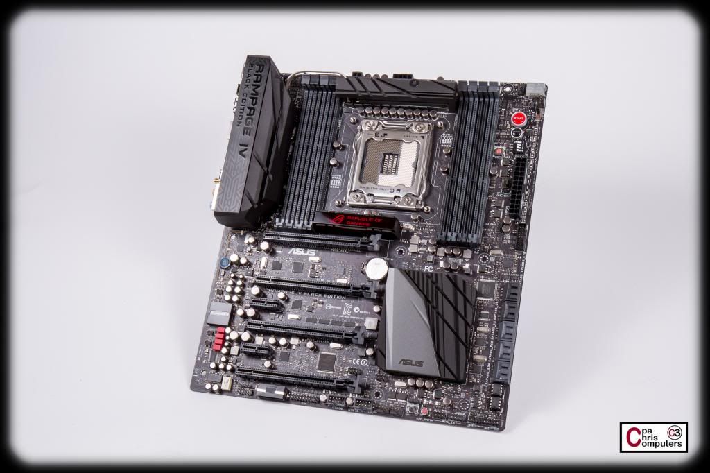
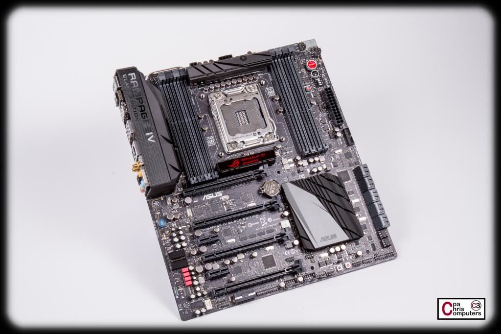
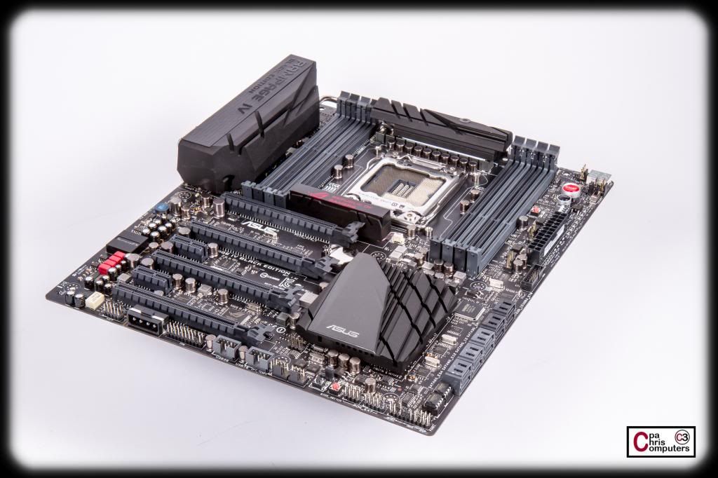
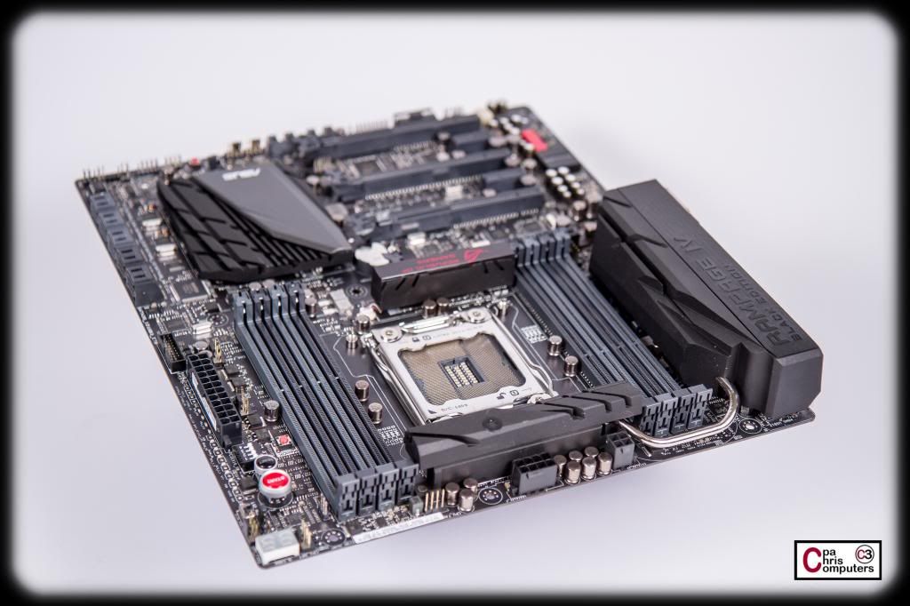
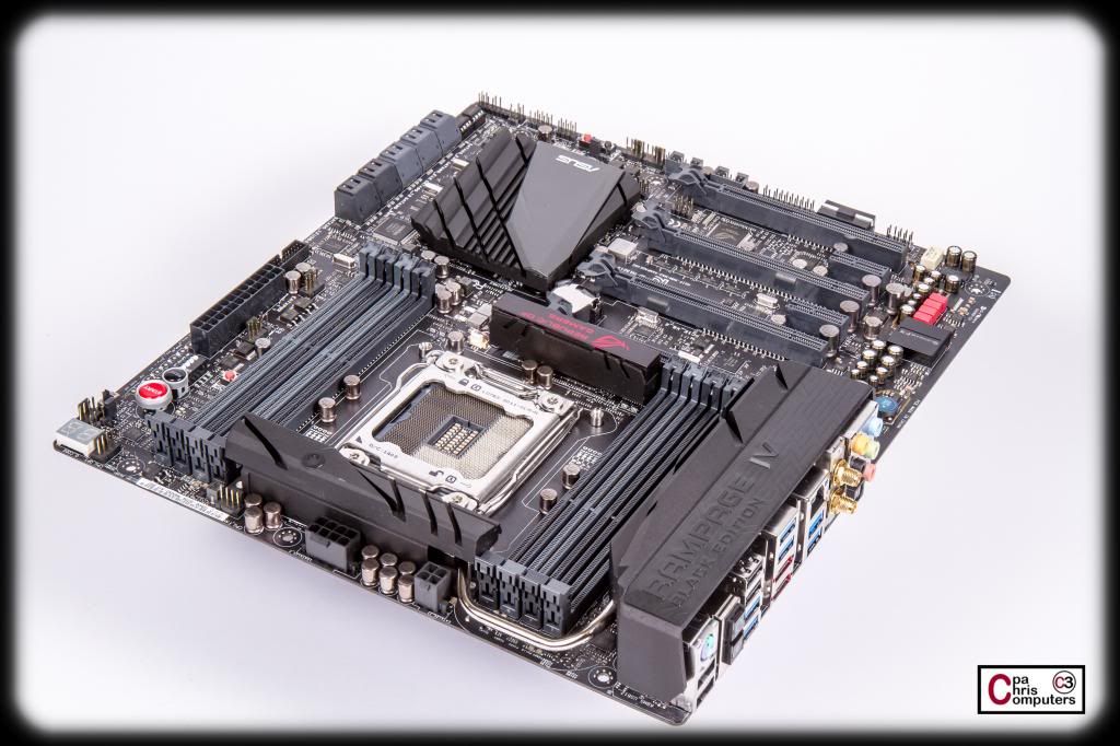
Some glamour shots of the RIVE BE.....
It really is a beautiful board even with the stock heatsinks. I'll leave these on until I know that everything is working....and then I'll be ready to block the board. Can't wait to see this beauty with those acrylic blocks and pink coolant running all over it.
They must just match the product to the quality of the build, in which case this deserves 780 Ti's
Most sponsorships are highlighting flagship products anyway.
i5 2500K @ 4.9GHz+ 8GB G-Skill RipJaws DDR3-2000 @1600Mhz CAS 6 Asus P8P67 Pro CrossFire 6970's @ 950/1450
Xeon X5677 @ 4.5Ghz 6GB G-Skill RipJaws DDR3-2000 @1600Mhz CAS 7 Gigabyte EX58-UD5 4870x2
i7-880 @ 4.2Ghz+ (still playing) 4GB G-Skill RipJaws DDR3-2000 @2300Mhz CAS 9 Asus Maximus III Formula MSI Hawk 5770
indeed
Kind words. Thanks tool_462! And your totally right....sponsors care about promoting their products. Not about what the ultimate use of the machine will be.
A few unboxing photos.....and then I'll post the glamour shots.
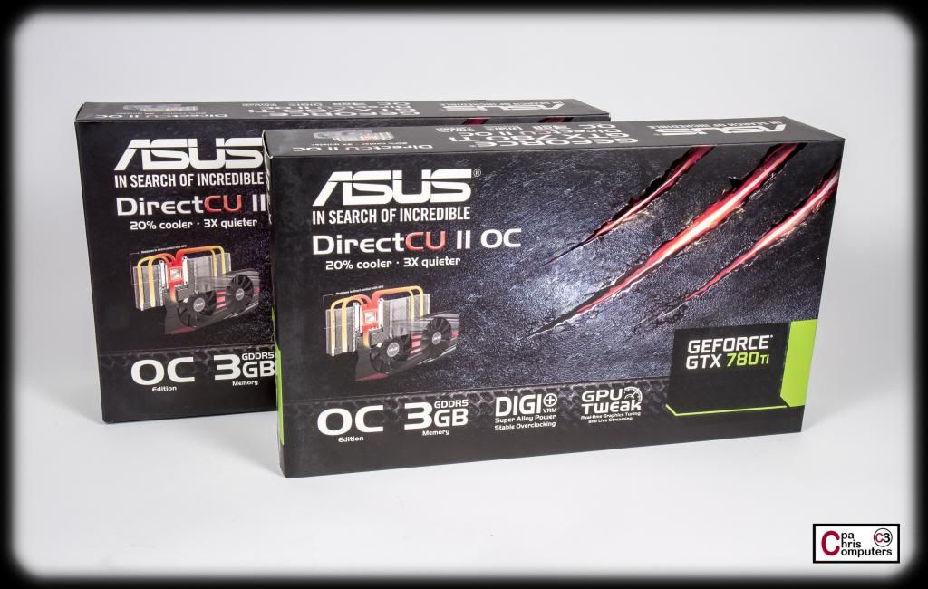
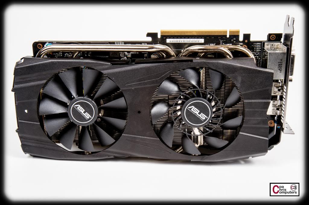
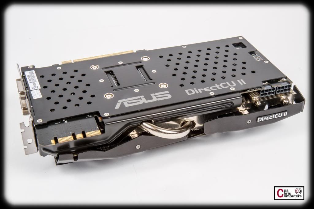
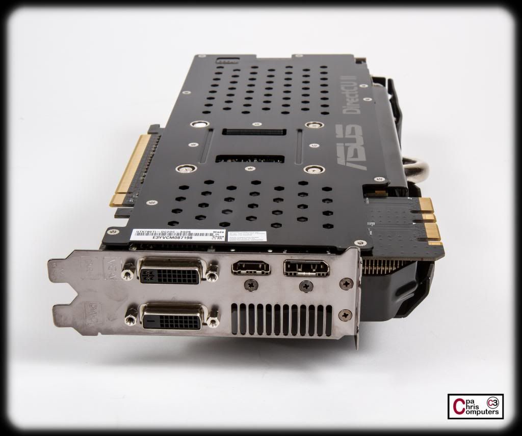
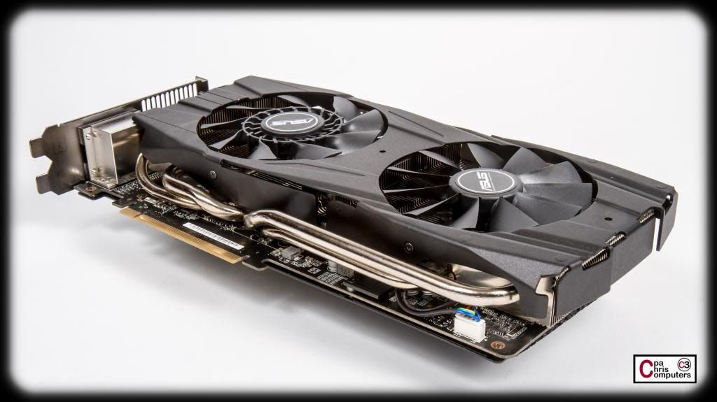
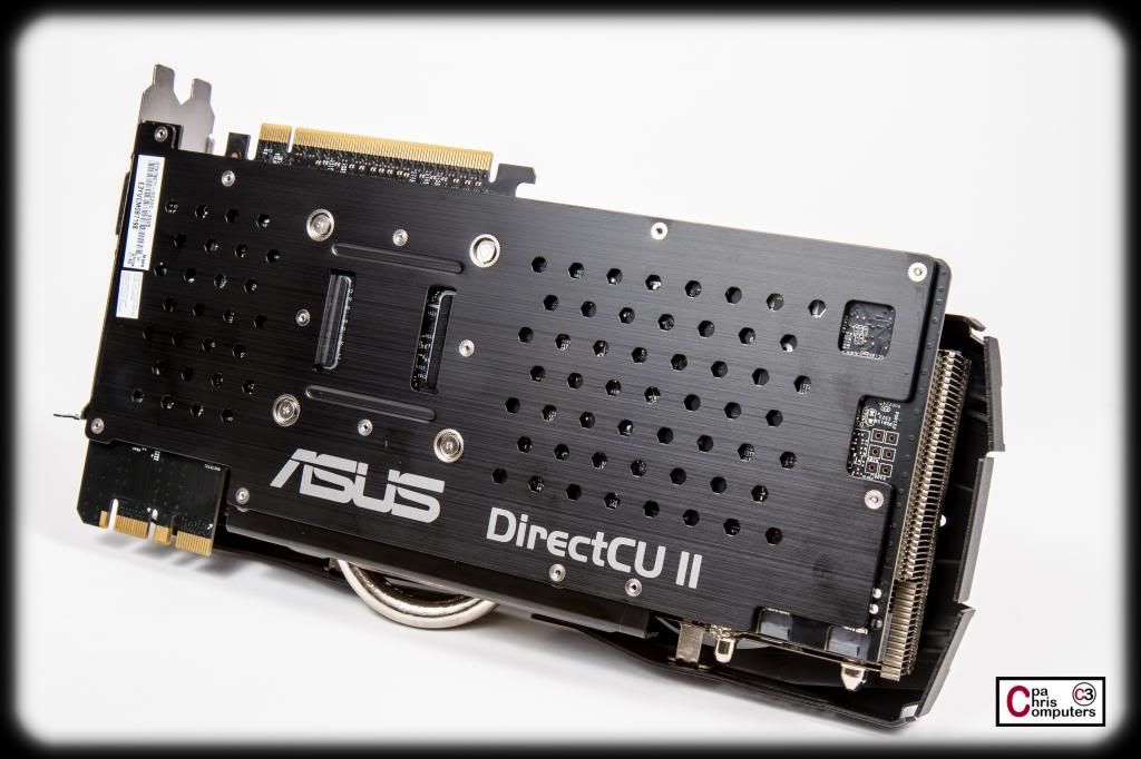
ASUS has been gracious enough to provide 2x of their GTX 780 Ti's DirectCU II OC graphic cards. Not a reference card.....this baby has the ASUS custom PCB and power delivery system, as well as their custom cooling solution with dual fans.
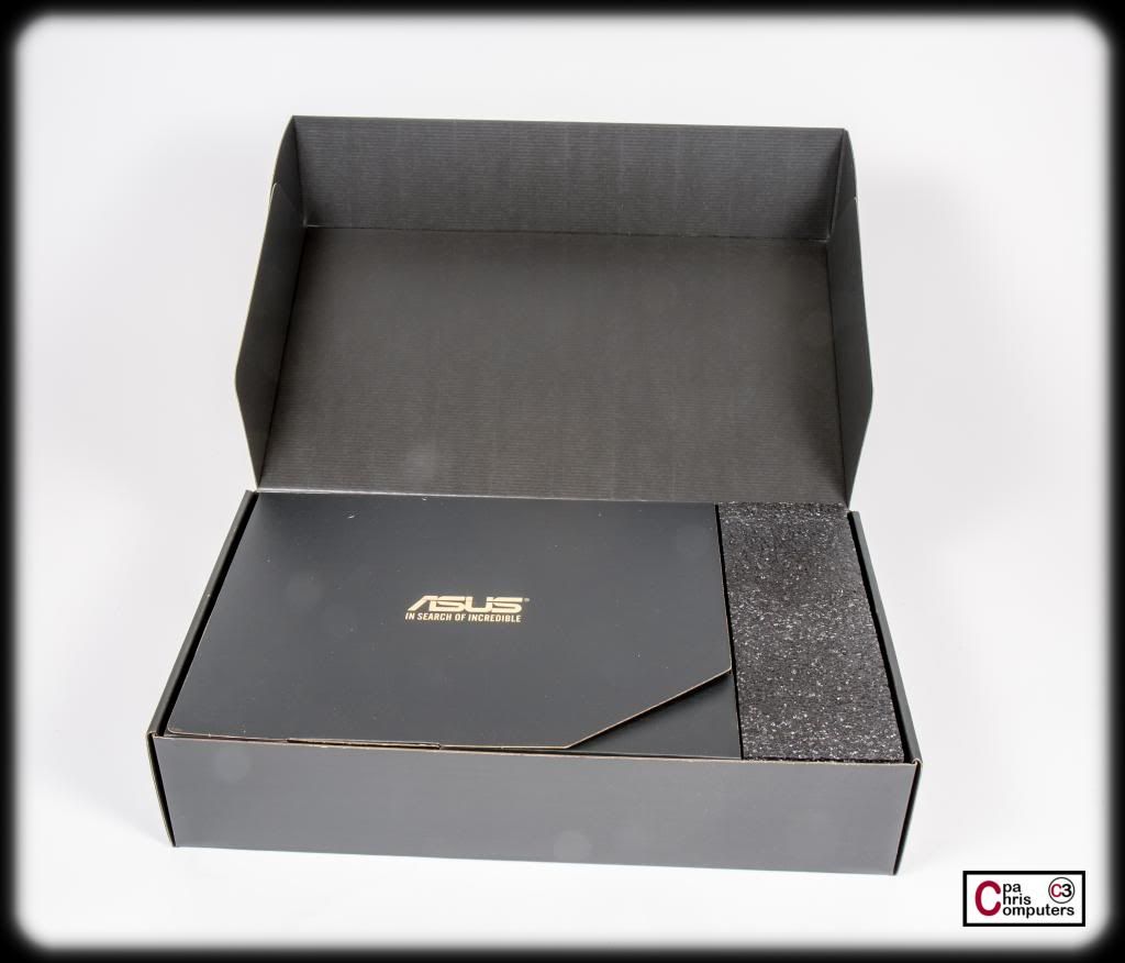
Inside the glossy marketing cover is a simple but elegant box with the ASUS logo in the center. In search of incredible. Always liked that slogan....
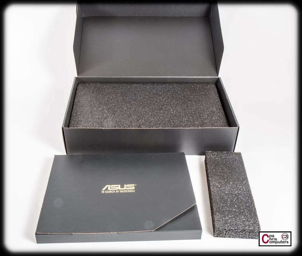
Inside the box is another slim box that contains the accessories and some foam padding on the right....
Underneath the accessory box is another slim layer of foam padding.....
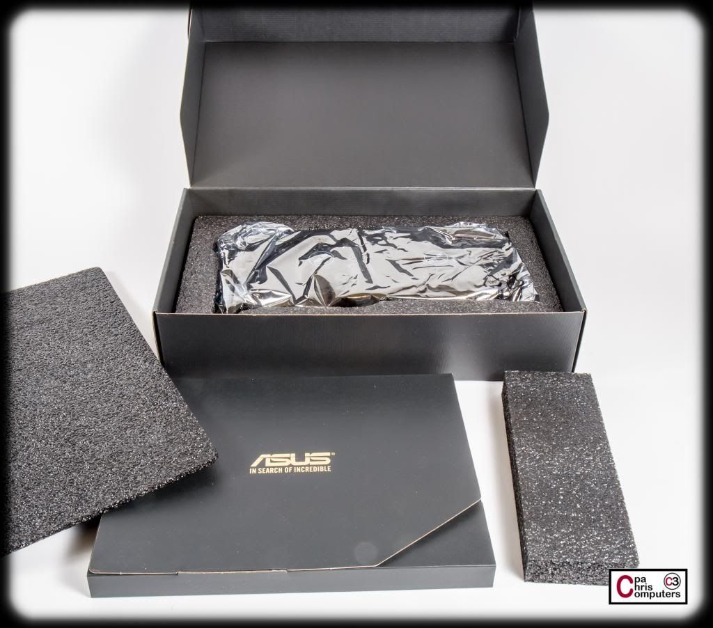
Underneath the 2nd layer of foam padding, is another ring of foam protection with the card itself in the middle. So it's well protected.
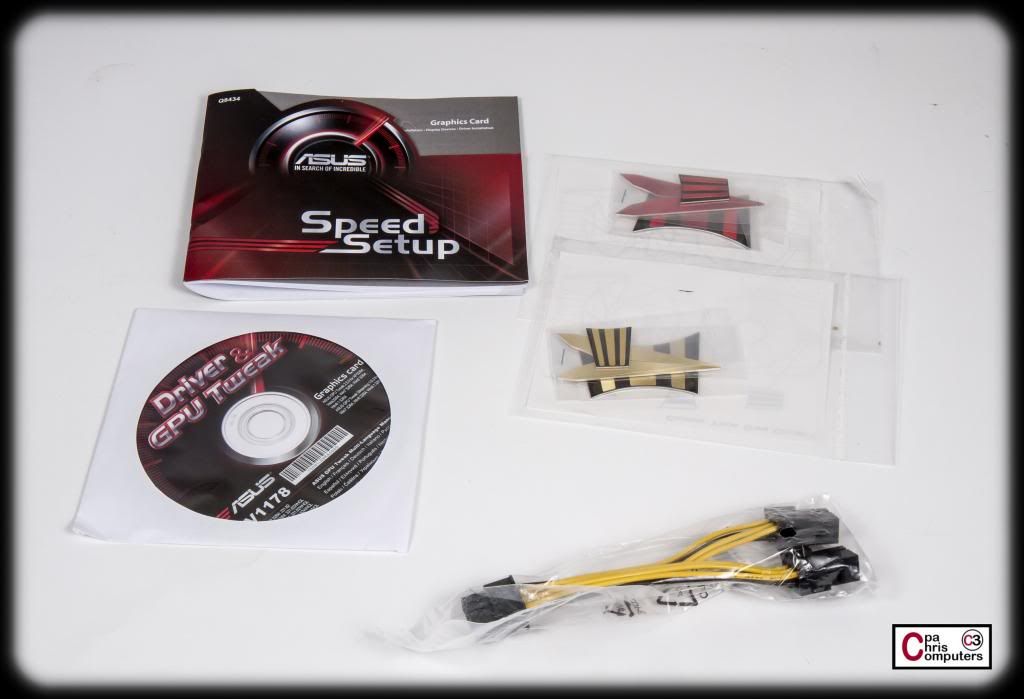
Here is what is in the accessory box. It's not much, but I think one of the accessories is kind of cool. There is a mini-manual (not much in there), DVD of drivers, power connection adapter, and some aluminum bling to put on the card. The power connection adapter could be useful for a lot of people I'm sure. Takes 2x 6pin connections and turns them into one 8pin connection. But...I think my Corsair AX1500i should have plenty of connectors without use of the adapter.
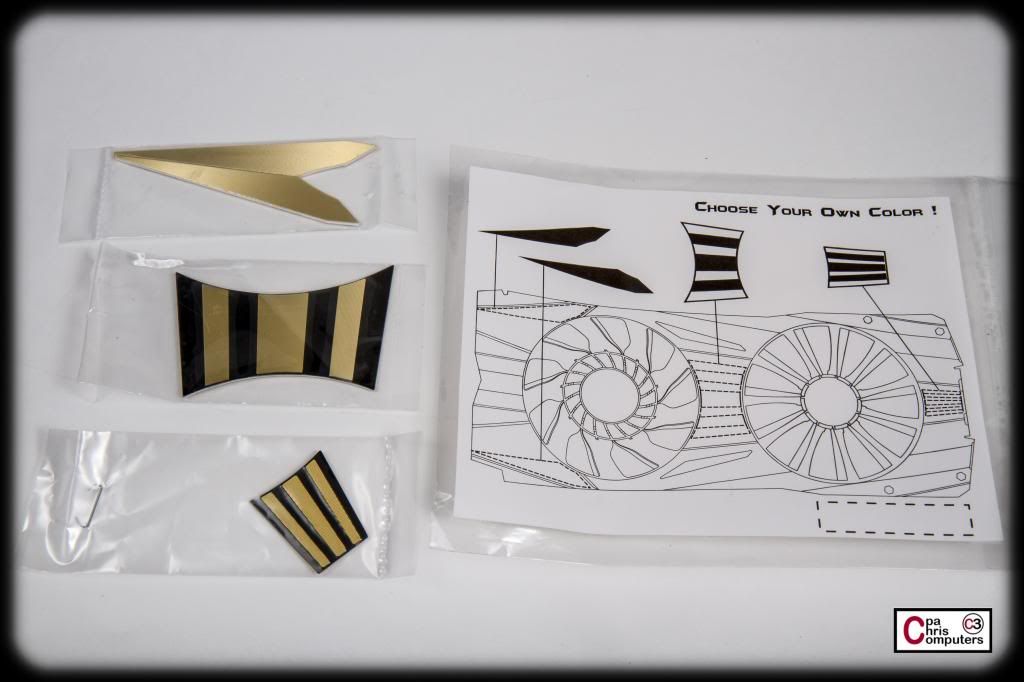
The aluminum bling is what I find interesting. They are colored aluminum pieces with sticky tape on one side. Comes in both red and gold flavors. The idea is you get to pick which one fits your build colors better, and install those yourself. You can see in the picture down here where they go. Think of these kind of like the Corsair accent rings on their fans. It's simply a quick and easy way to customize the component quickly to go with your colors. And kind of like I'm planning on painting the Corsair rings my own custom color....you could easily paint these aluminum pieces also to go with your theme. Nice touch ASUS.
Even though I'll eventually block these cards, I'll probably paint a set of these pink and stick them on to see how they look. Plus, I plan on putting the cards through their paces with the custom ASUS air cooling on first anyway....just to see how it performs.
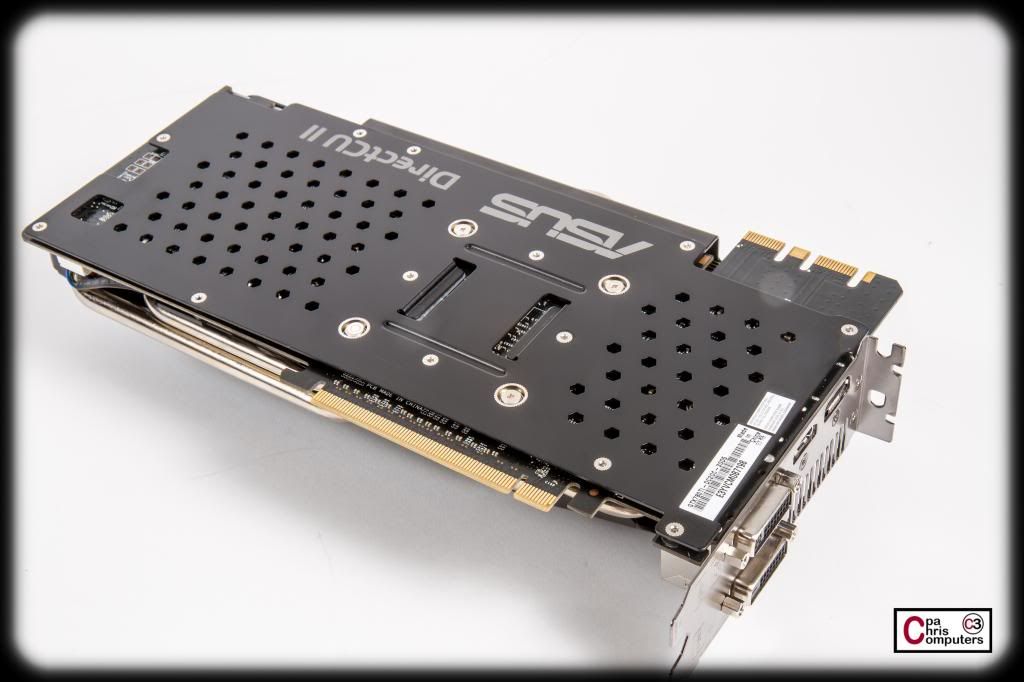
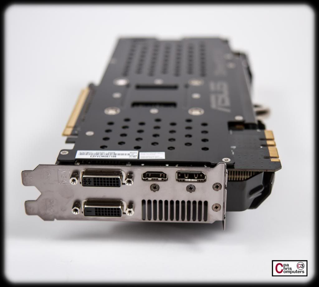
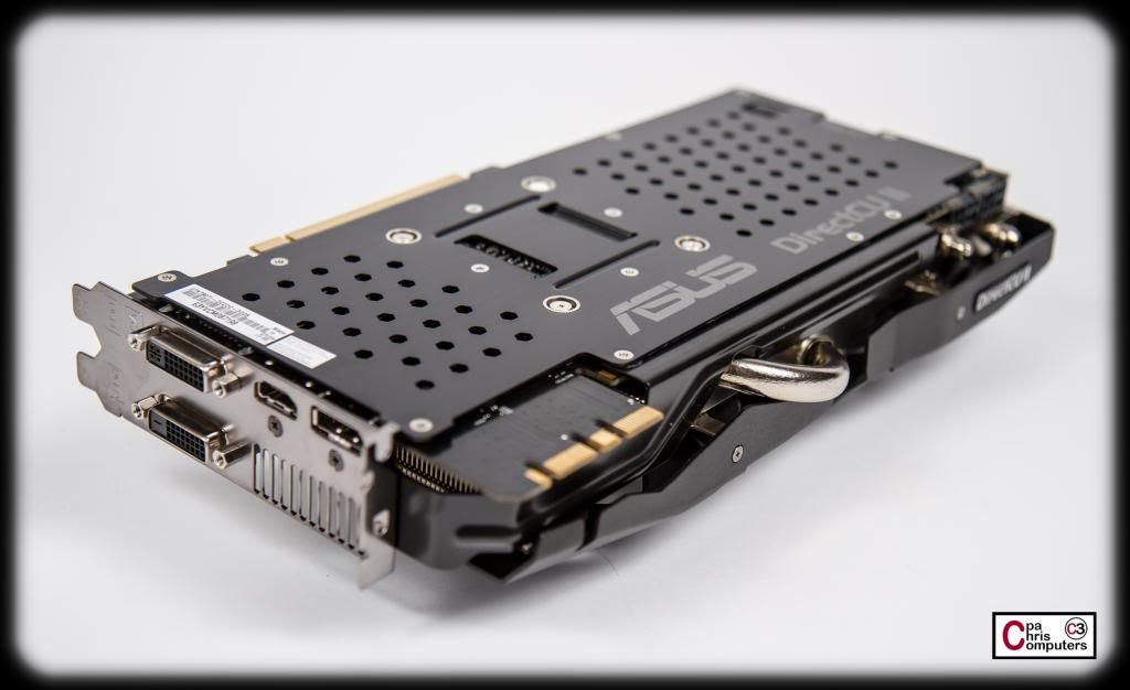
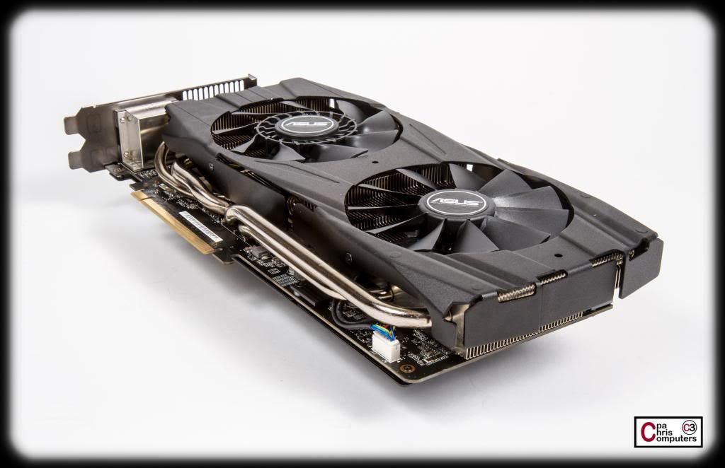
You can see the side of the card in this picture where the stickers would go....
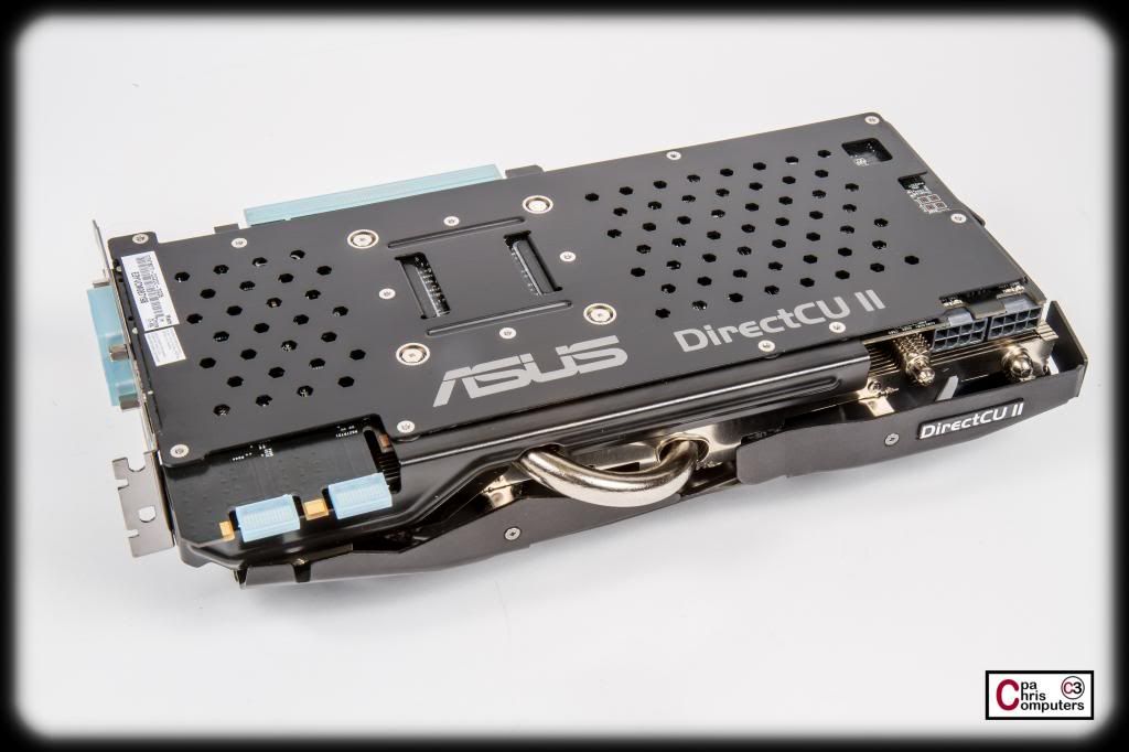
...and here is the other side of the card.
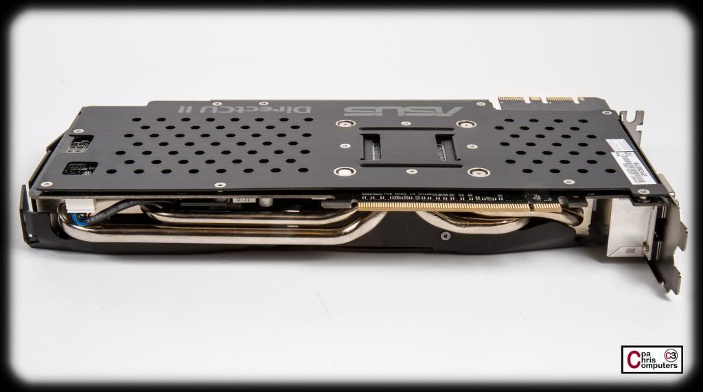
It really is a mean tough looking graphics card with those pipes showing and massive heatsink underneath the dual fans. Even the backplate has a mean aggressive look. And I love that it comes with a backplate. This should be required on any card in the $700+ range. I really like the aesthetics of the cards.
I took a lot of glamour shots also....and I'm working on processing those right now, so there will be more pictures of the cards soon.....
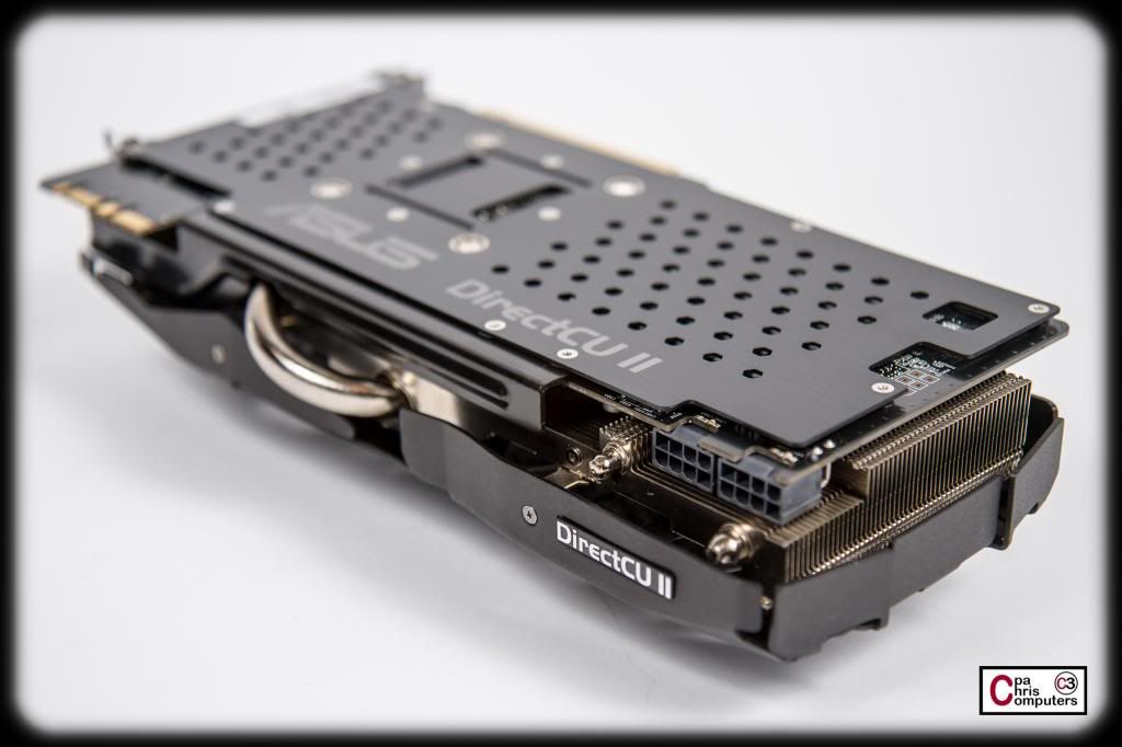
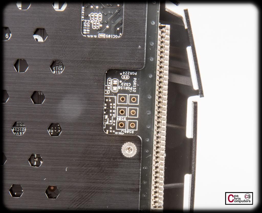
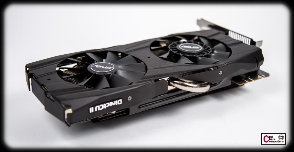
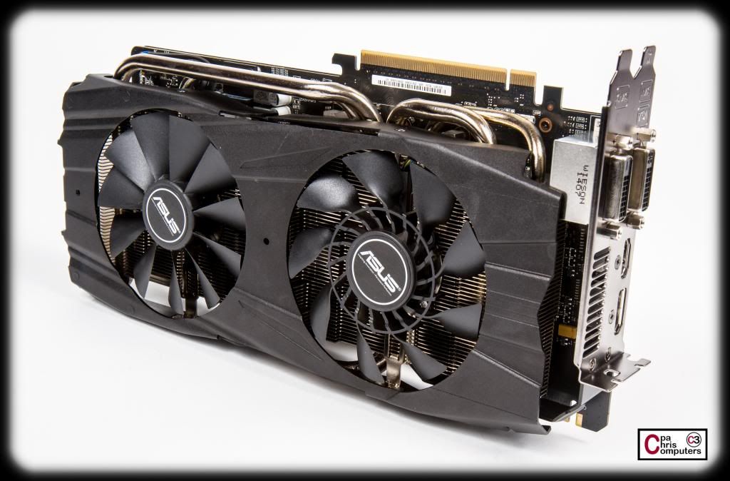
Glamour shots for the graphics cards!
These really are good looking cards.....
I keep coming back to the words "mean" and "tough"....but I think that describes them best. These cards look like they came here to kick some butt and chew some bubblegum. And they're all out of bubblegum.
I've got my i7-4930k that will be going in this build....so after my low profile air CPU cooler gets here tomorrow, I should have everything I need to fire this baby up on air and make sure everything is in working order. Then I get to do the fun stuff. Cooling loop, fans, cabling and lighting.
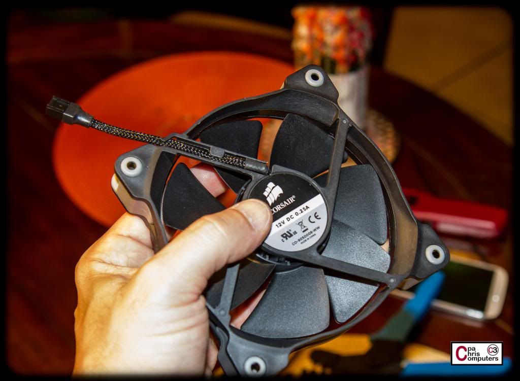
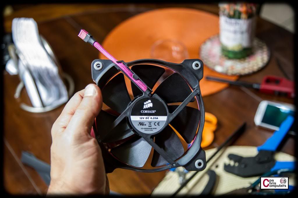
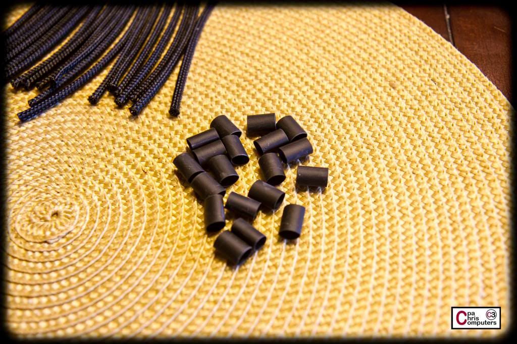
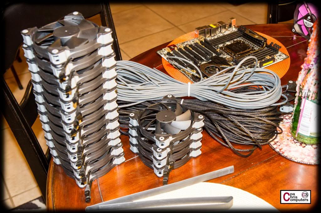
Trying out a couple of options on sleeving the fans. I'll be using the same approach as the BBBB....where all fans will have the power cord shortened significantly. I like to run custom power harnesses to each fan. It can be cleaner looking to wire all the individual fans together into one cable that runs to the power source....but this creates a nightmare if you have a fan go out or want to take an individual fan off to lube. The way I do it leaves all fans with the option to be removed individually from the build and/or replaced. The custom power harnesses shouldn't ever have to change.....so less chance of rewiring work this way.
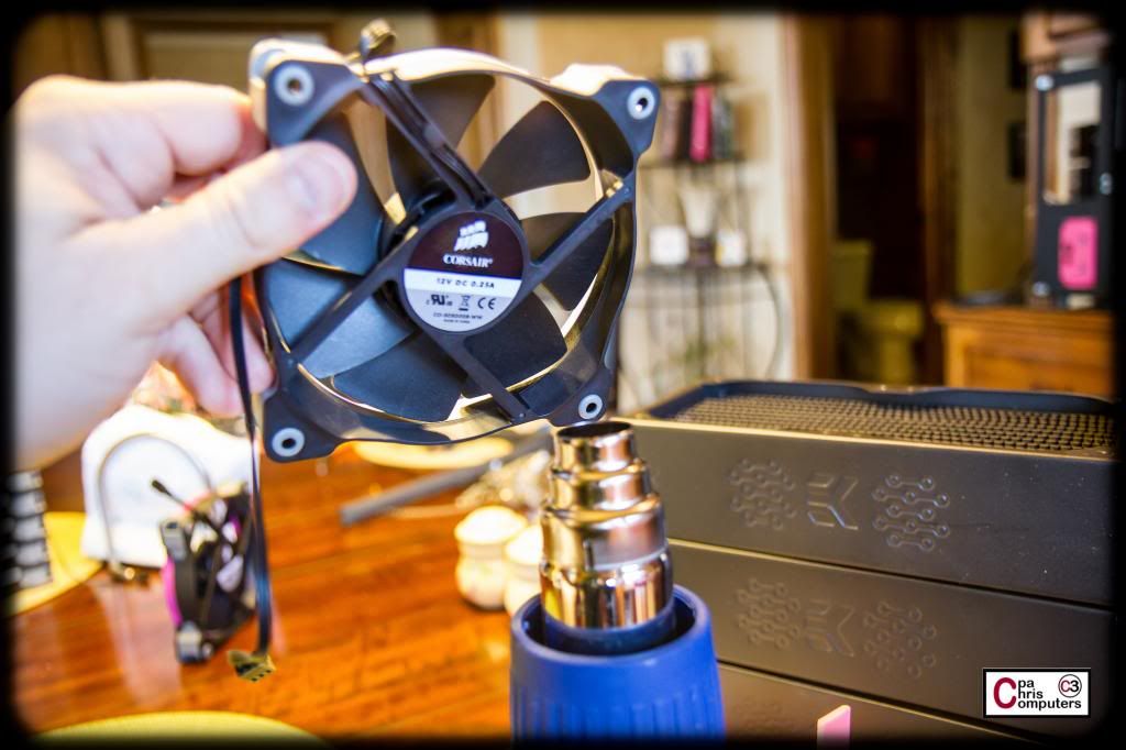
The stock cabling on the Corsair fans isn't bad. It's the flat cable type. But naturally I'll be putting sleeve on this while I shorten it.....
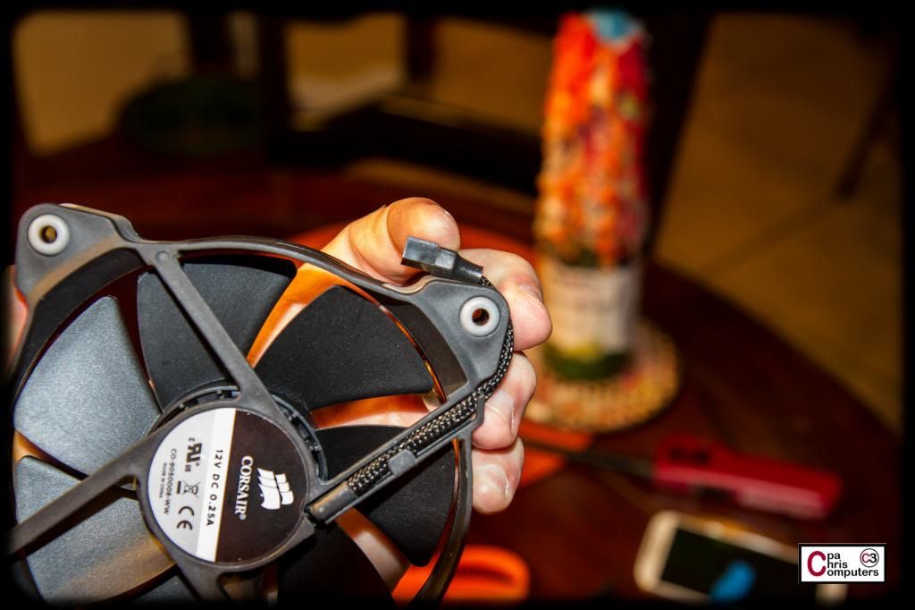
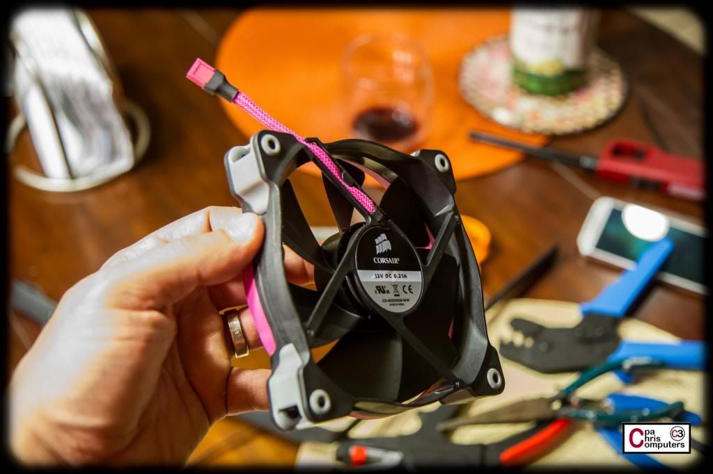
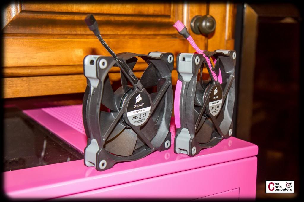
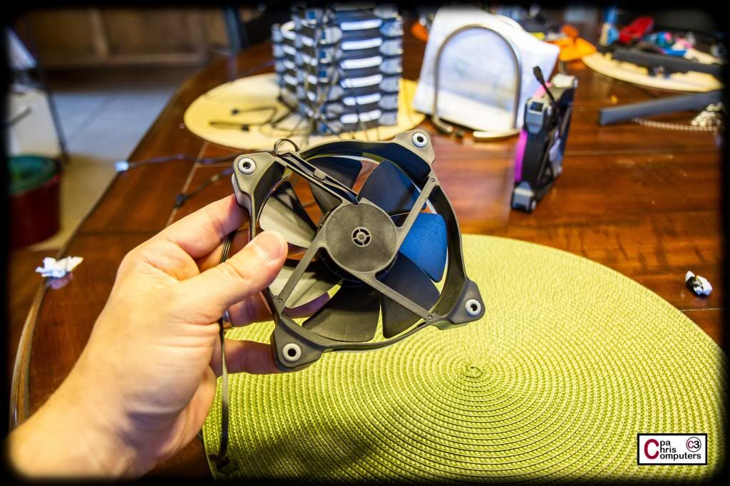
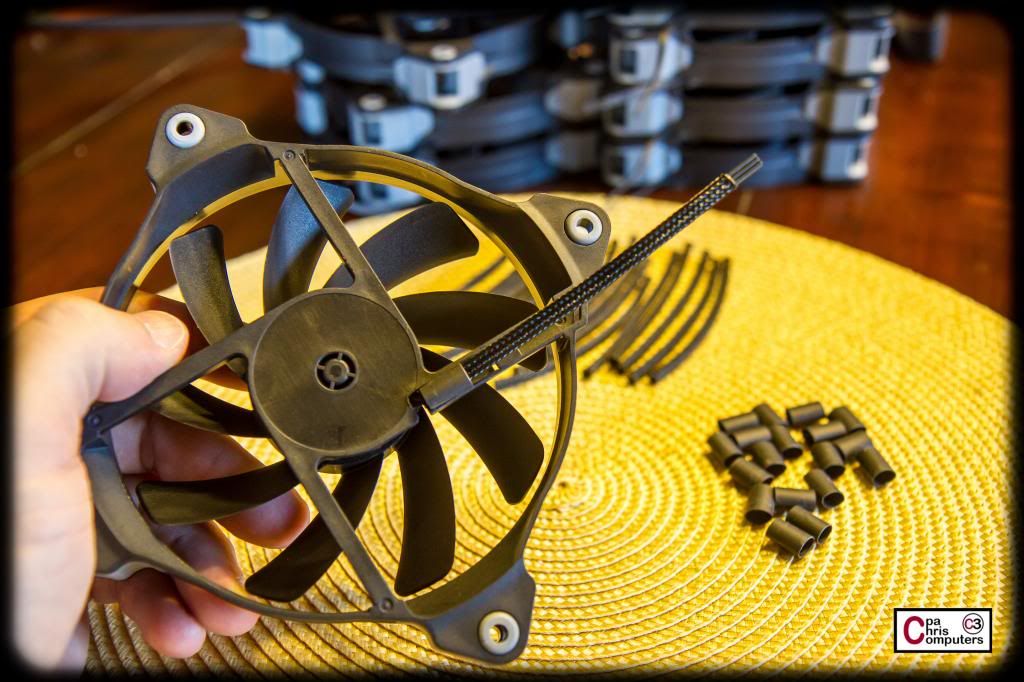
Here is a pic of the black Telios on the fans, with wires cut to 4 inches....
This length lets me bend the connection around the corner of the fan....
...as well as around the top. Plenty of options for where the power harnesses will connect....
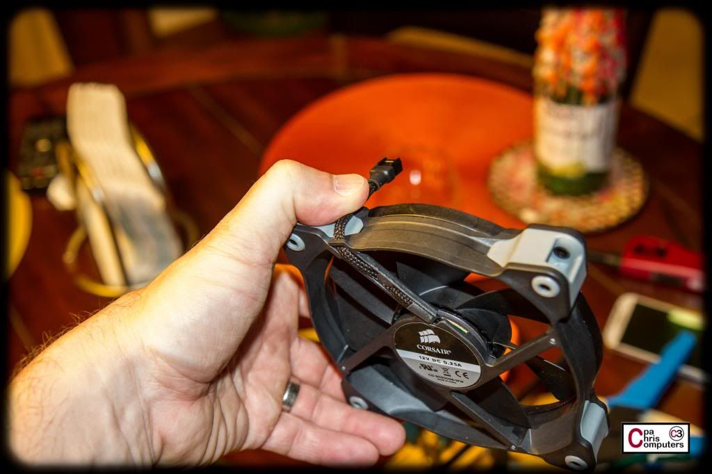
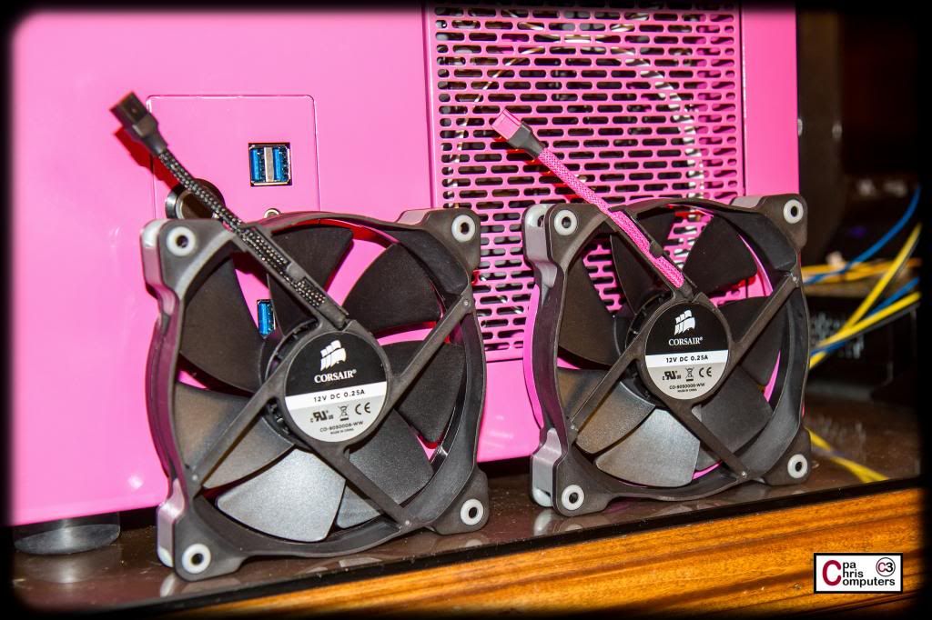
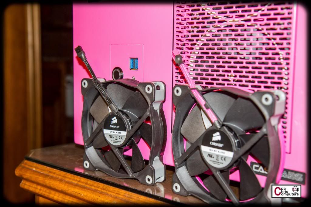
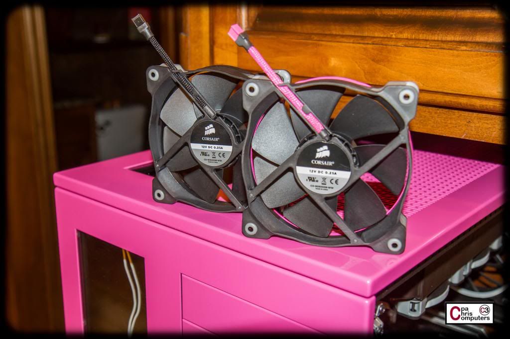
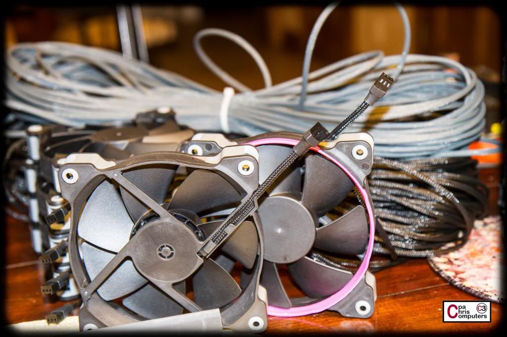
And of course I also have the option of the custom dyed pink Telios and pink fan connectors...
It really is an almost perfect match for the powder coat on the case. I'll be doing my full dye job on the white Telios sometime this next week.
I just need to decide if I want to keep the fans all black with the sleeving and connectors....or use the pink for some contrast. All black would be kind of stealth mode....since the inside of the case is black. The fan cabling would disappear into the black rads and black case interior. Or.....should I use the pink sleeving and fan connectors for some pop on the contrast.
I'm definitely going to use some of the pink Telios on the 24pin and 8pin connectors. Just need to decide what to do with the fan cabling. What would you do?

Nice shots. I need to figure out what you use your pc's for, looks to me like it has enough USB and sata options.
The BBBB was my "Adobe rig". Photoshop and video editing.
The PPPP will be a screaming fast friend finder in FaceBook and a blazing Pinterest browser. Not to mention online Scentsy ordering will be sped up tremendously.

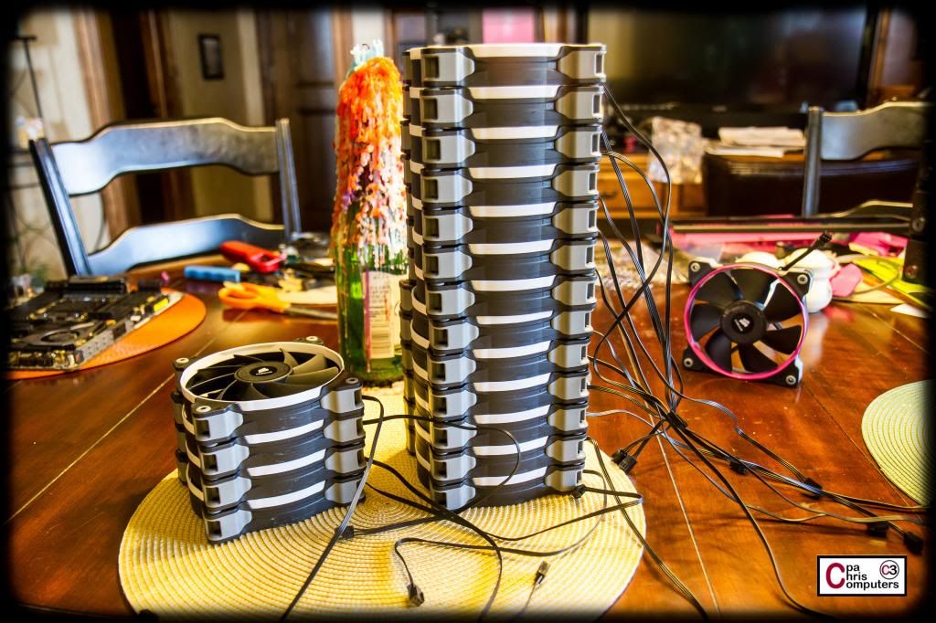
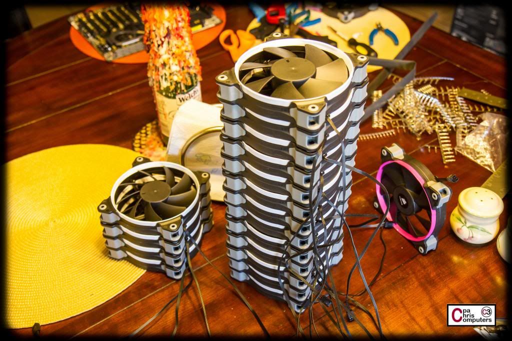
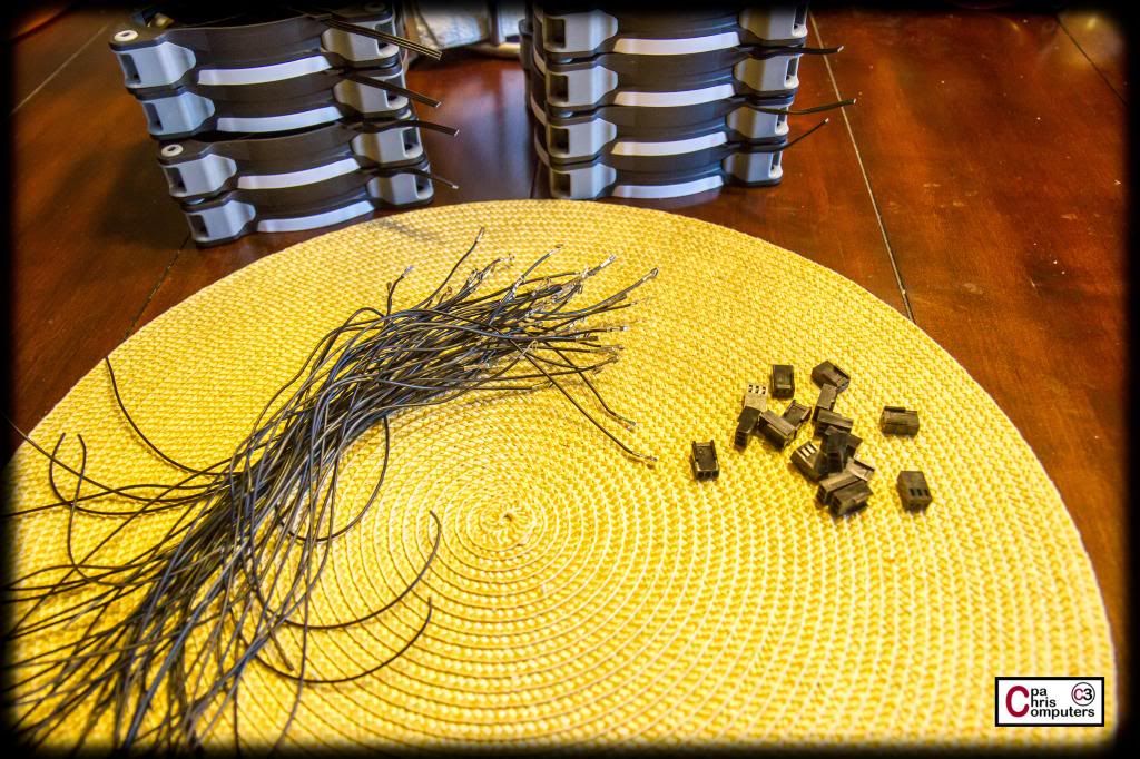
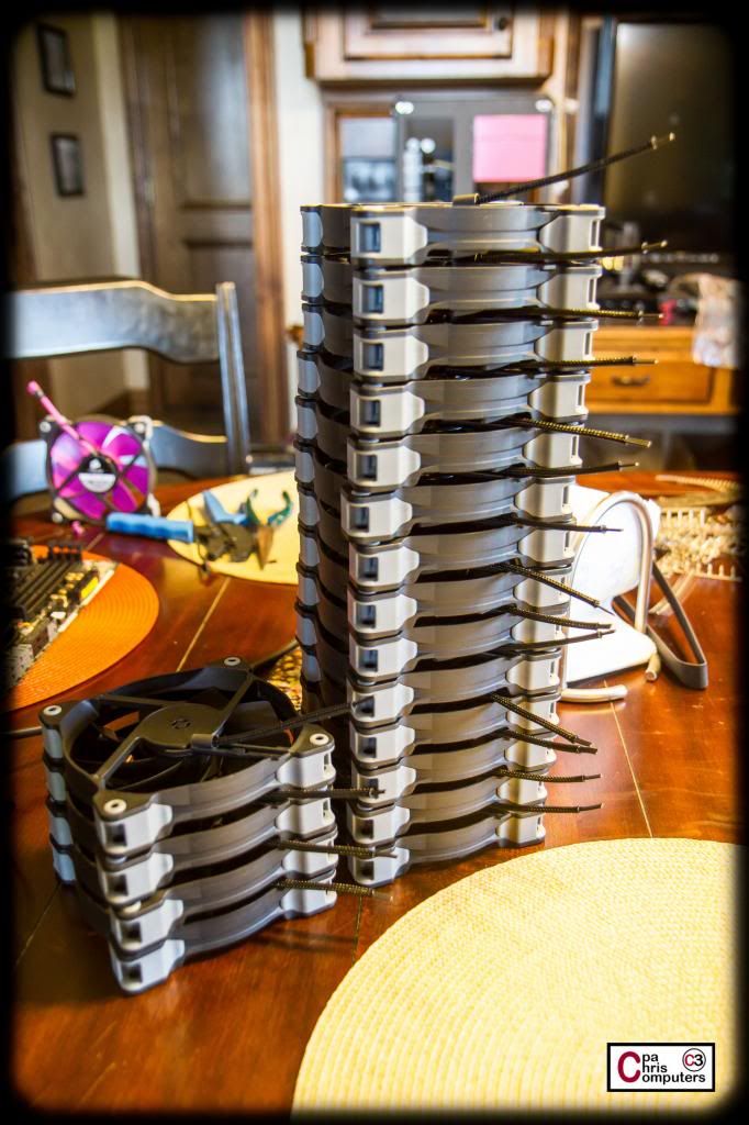
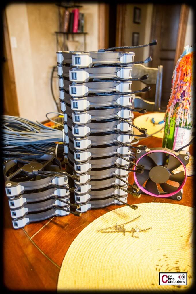
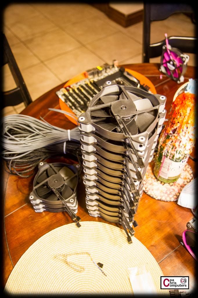
Got some work done on my fans today. I like to pick one step and perform it for all the fans, and then start on the next step for all the fans, ...etc, instead of working and completing one fan at a time. Here are the steps I got done tonight.
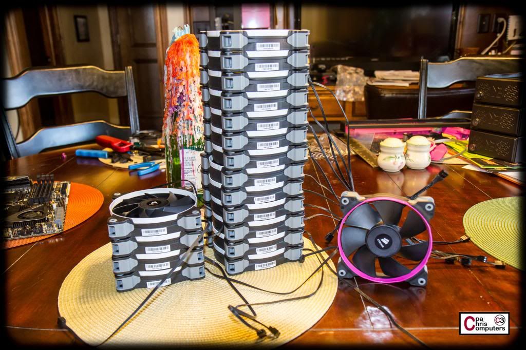
I started with my stack of fans. A manageable stack......17 of them in all that still need some love. I sacrificed a few to paint samples, and have ended up with the exact number I need of the SP120's, and I have 2 extra AF120's. Although....I may find a spot to use these before I'm done.
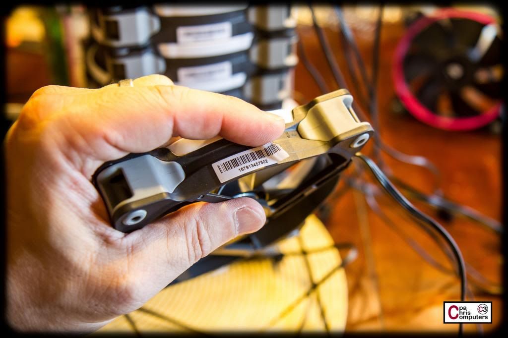
Anyway, the first thing I need to do is remove all the stickers from the fans. That white serial/lot number sticker is what caught my eye first. They all were very easy to remove and peeled off leaving no residue.....
Rinse. Repeat. And now my stack looks like this.
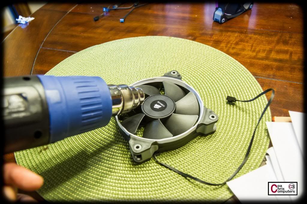
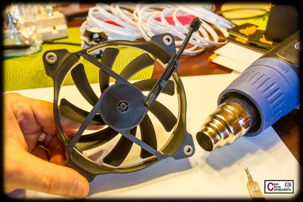
Next step was was to remove the sticker from the fan blades. I won't end up using any stickers at all on the fan blades. To me, when there is a sticker on a spinning fan blade, it always makes it look off or out of balance. It's almost impossible to get it perfectly centered on all sides...so when it spins it just looks "off". So...my blades will be naked. They like it that way. I used a touch of heat from my heat gun, and then these stickers pulled right off leaving no residue.
Ahhhhh. That's better.
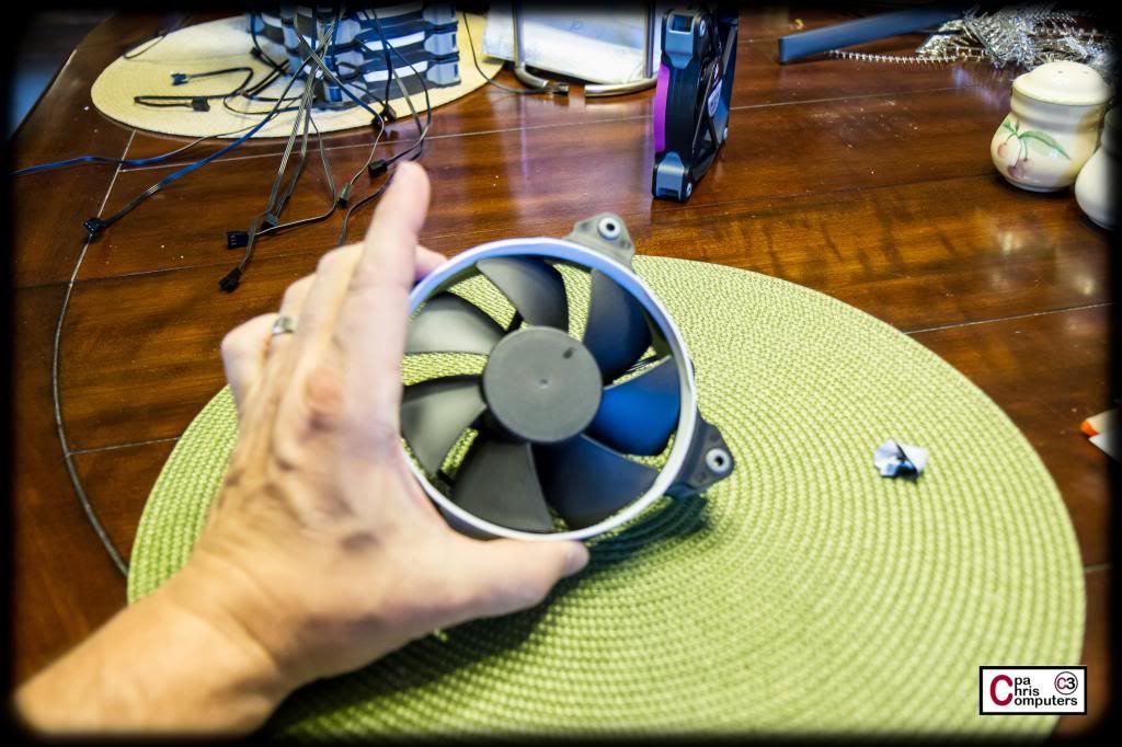
Next step was to remove the sticker from the frame. Again, I had to use a touch of heat....but once I did the sticker pulled right off leaving no reside. Now....I WILL put a sticker on the fan frame. It just doesn't look finished without out. But...just like I did in the BBBB, I'll make some custom vinyl stickers in the build's colors for these spots.
Naked for now.....
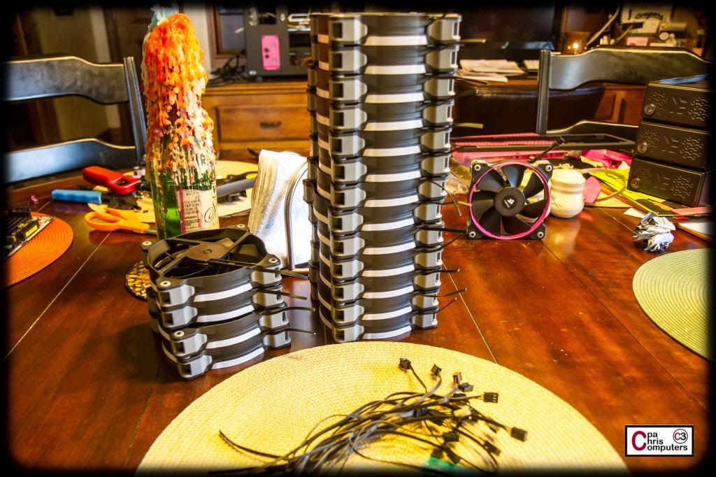
Rinse. Repeat. And now my stack looks like this.
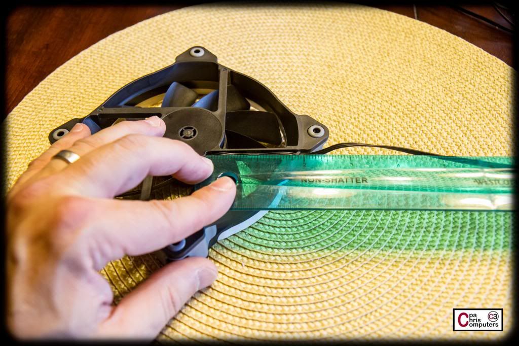
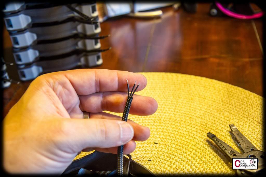
Next step was to shorten the cables coming out of the fan. I already knew from my sample fan that 4 inches would leave the fan connector at the perfect spot where I could either wrap it just around the bottom of the fan frame, or just around the side. Short enough where it's out of the way....but long enough to go where it needs to go. So I just got a ruler, measure 4 inches from the wire's origination in the fan frame, and snipped them right off.
Rinse. Repeat. And now my stack looks like this.
I went ahead and removed the black fan connectors from my snipped wires. I won't use them in this build. For this build, I'm using connectors supplied by Lutro0 Customs. But....you can't ever have too many black fan connectors....so I rescued them and through them in my supply drawer.
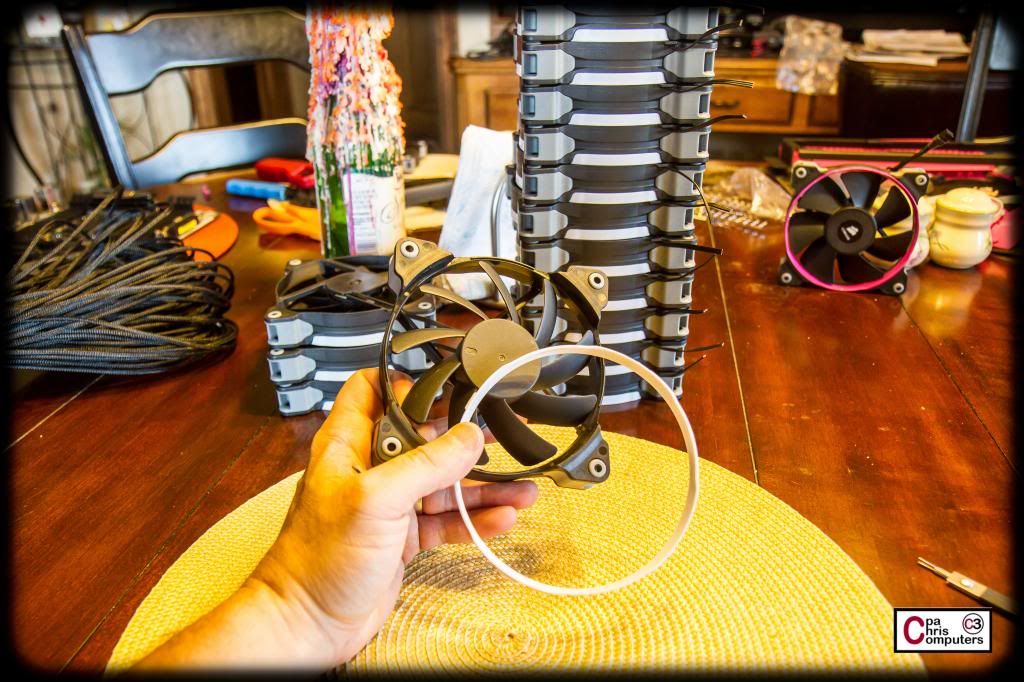
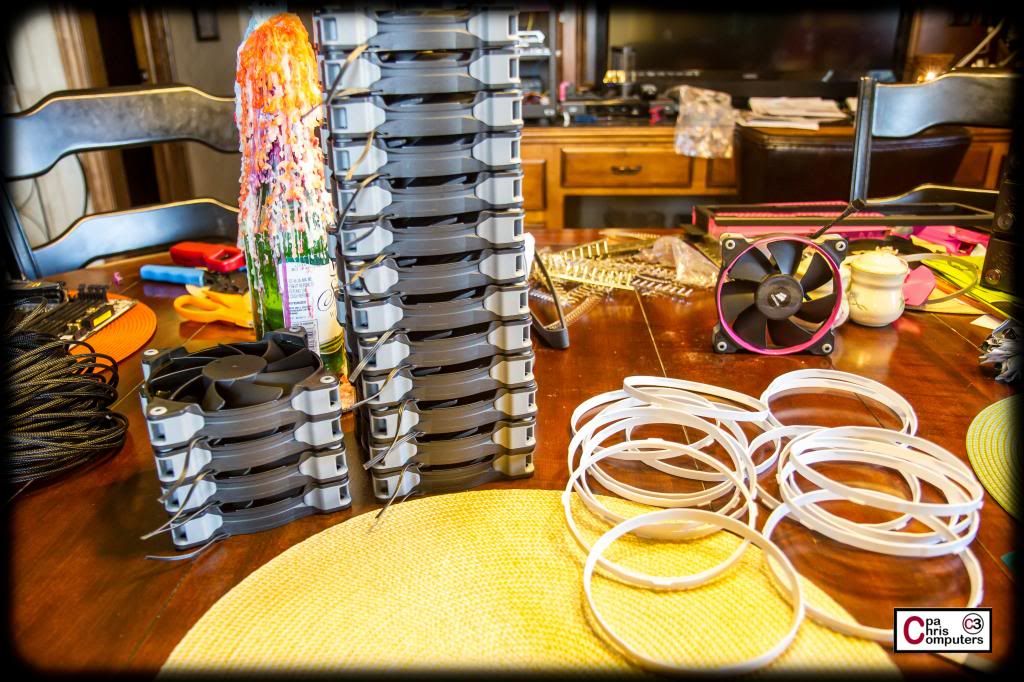
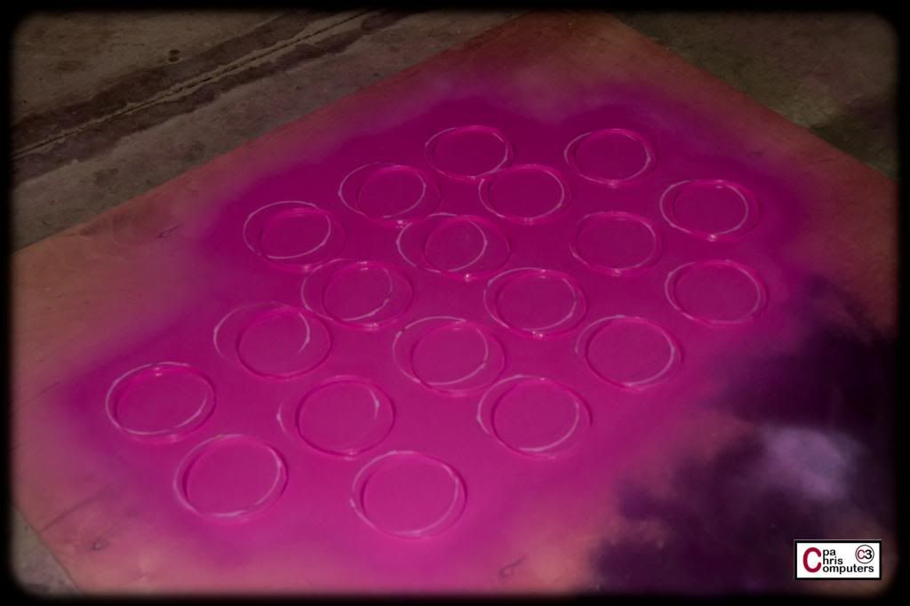
Next step was to remove the plastic accent rings from the Corsair fans. I'll paint these all pink, so I just need to get them out of the way for now. Oh...and by the way....Jenn chose the all black fans, with the pink accent ring. So....I think that was fan option #1 when we did the color combinations for everyone.
Rinse. Repeat. And now my stack looks like this.
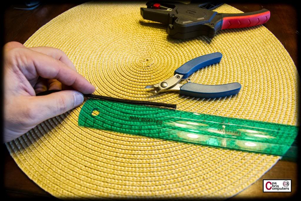
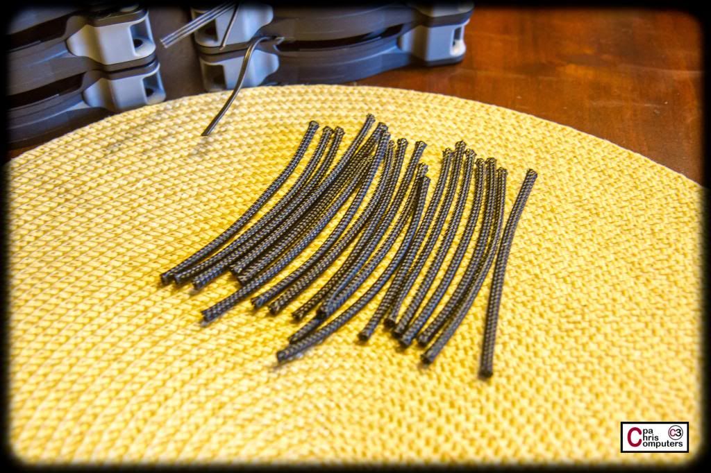
Next step was to cut a piece of sleeve to use on the fans. I knew that if I cut a 3.75 inch piece of Black Telios, that it was going to fit perfect. So, I got out my ruler, and started snipping pieces.
After each cut, I'd go ahead and use a lighter to burn the ends just a little and taper them in. Don't want them start unraveling....
Rinse. Repeat. And now my stack looks like this.
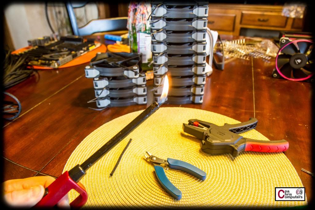
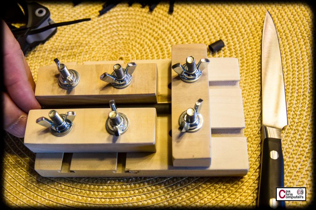
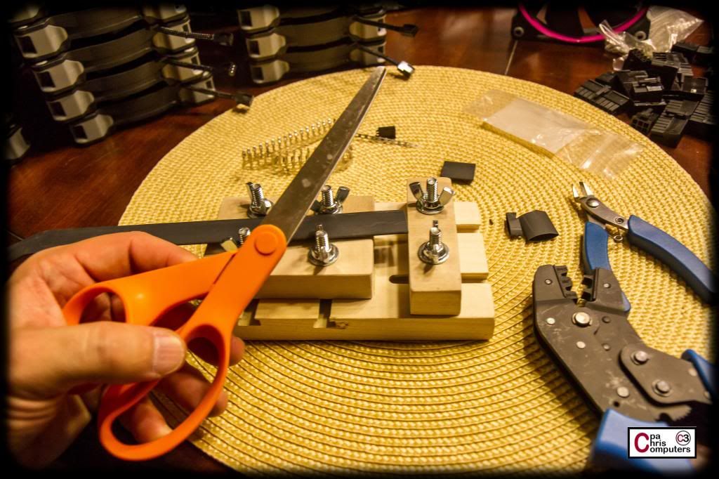
Next step was to cutt a small piece of heatshrink to use on the end that attaches to the fan motor. So I got out my Lutro0 Customs jig, and started playing with it again. But even after trying multiple blades, I still couldn't get nice straight cuts the majority of the time.
But then I switched over to using scissors with the jig....and it worked perfectly for me. The jig still was doing the measuring for me, and I just kept pushing the shrink up so it was flush with the edge....and then cutting with scissors. Very easy. I now love my jig.
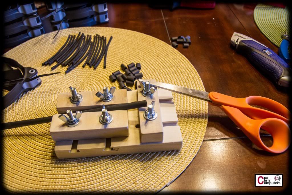
I ended up with a pile of perfectly sized and exactly the same size pieces of shrink to use on the motor side of the cable...
....and I went ahead and slipped on the sleeve and the shrink to each fan cable. I didn't use any heat because I didn't want to shrink the heatshrink yet....because I knew I would be wiggling the sleeve around a lot still while I put on terminals.....
Rinse. Repeat. And now my stack looks like this.
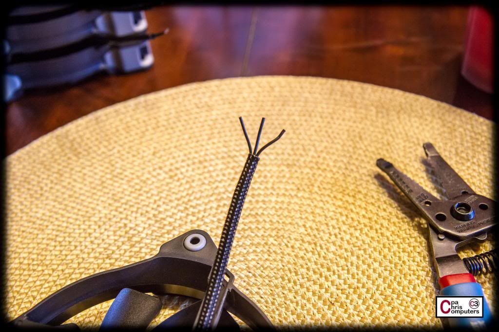
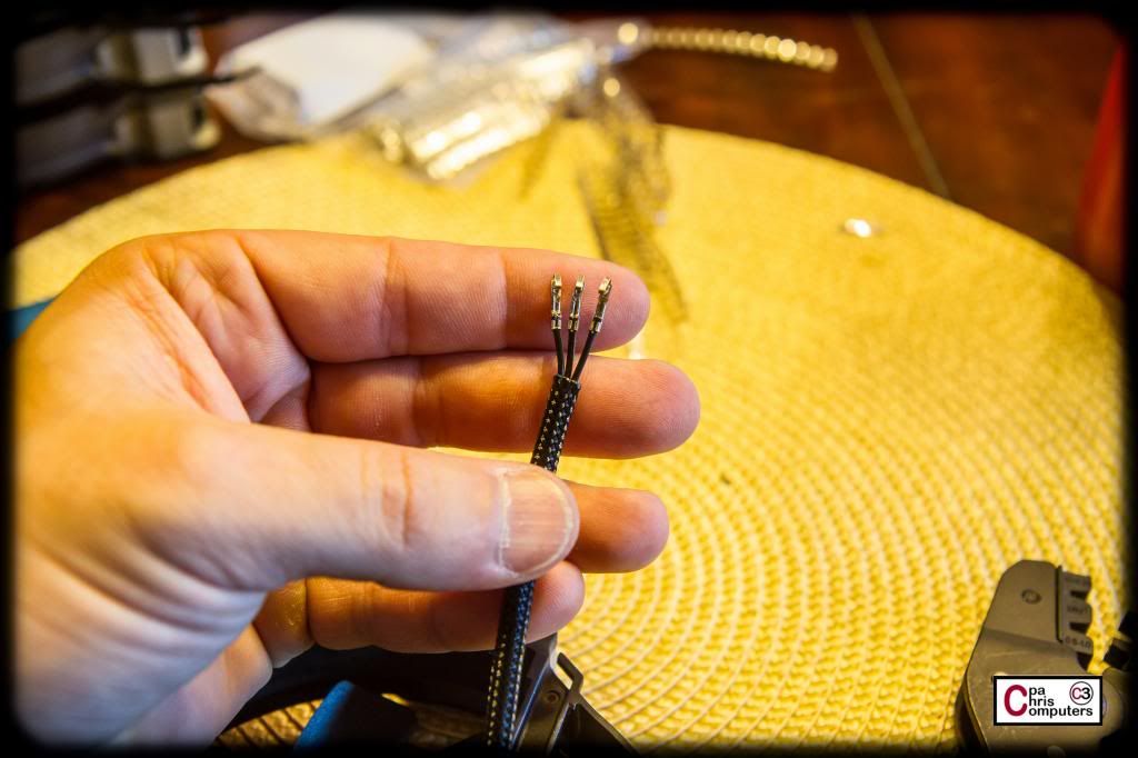
Next step was to put the fan terminals on.....so first I took the fan cable and separated the ribbon style cables into three distinct pieces.
To strip the insulation, I first tried my handy dandy Knipex wire strippers I got from Lutro0 Customs. But alas, even though the Knipex strippers work perfectly on the 16 AWG wire I have....they don't work on this thin 26 AWG fan wire. Too thin....wouldn't cut the insulation all the way through. I think the take-away lesson here....is that strippers work better on chubby things. Wait....that didn't sound right.
So instead, I used my old fashioned wire strippers. Still worked just fine. But not as fun....
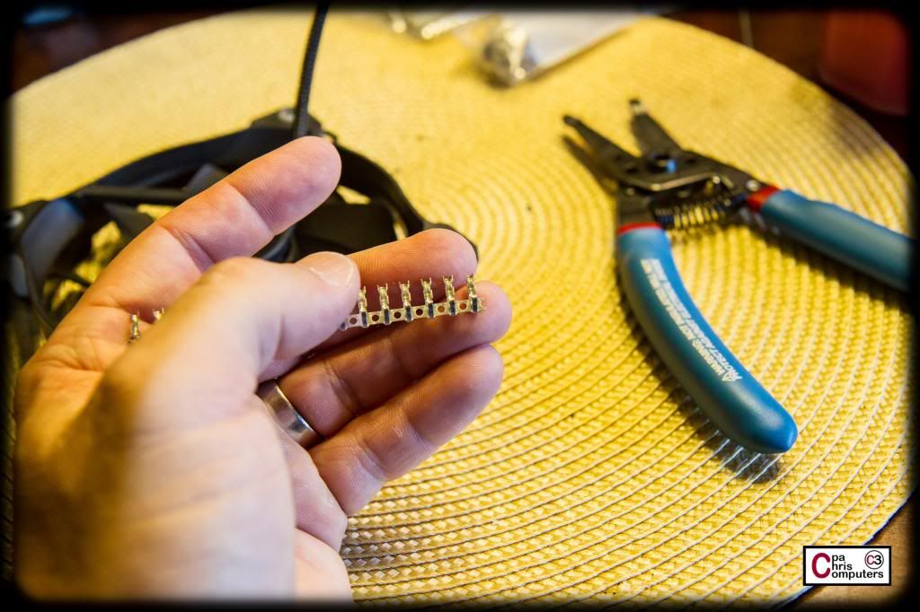
Then I attempted to put on the fan terminals. Before I go any further, I have to point out the issues I had with the female fan terminals I got from Lutro0 Customs. I don't know if you can see it in this picture, but zoom in and you'll see that the terminals are attached to the metal strip up by the tips of the terminals.
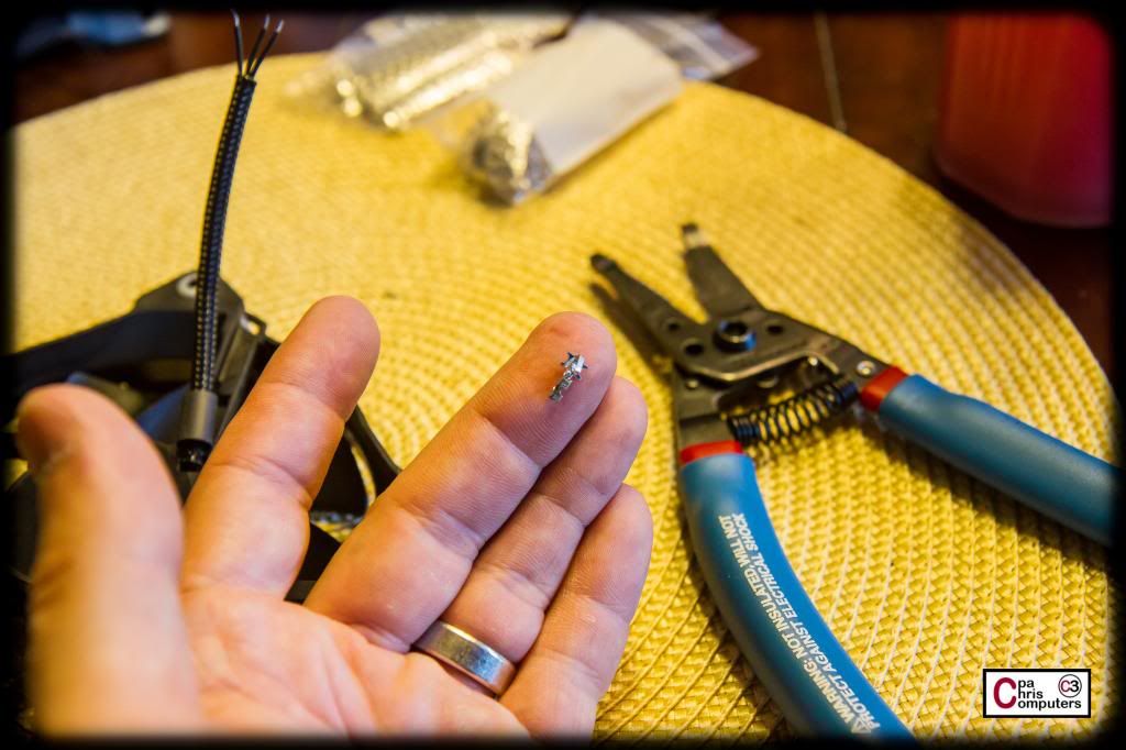
So....when you break them off of the strip, it leaves a portion of the strip attached to the fan terminal itself. It is absolutely unusable in this condition. The terminal won't even fit in a fan connector with this much extra stuff hanging off the sides. To get these to fit...I had to use a pair of flush cutters, and snip off the excess material on each and every terminal. Clearly I wasn't going to do that for long. Not sure what's up with these terminals. I'll ask Lutro0 and see if I'm just missing something....or if this was a strange batch that he purchased. But I couldn't get them to work.
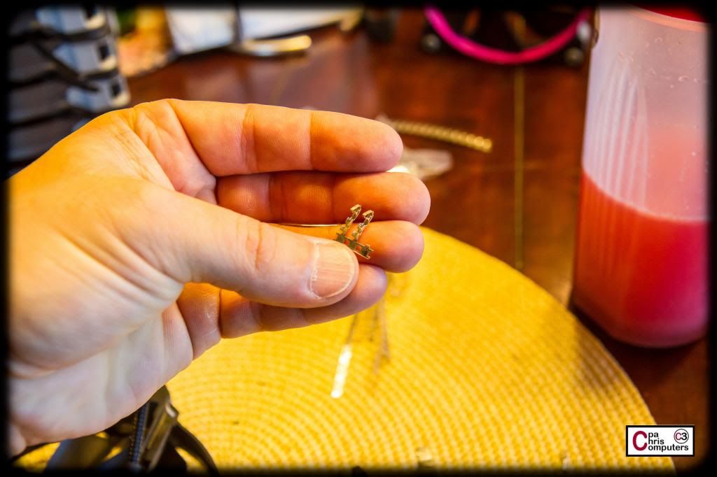
So....I opted for some old fan terminals I'd gotten from Frozen during my last build. They worked just fine.
The Lutro0 crimper does work flawlessly and is an excellent tool. Perfect crimps almost every time....
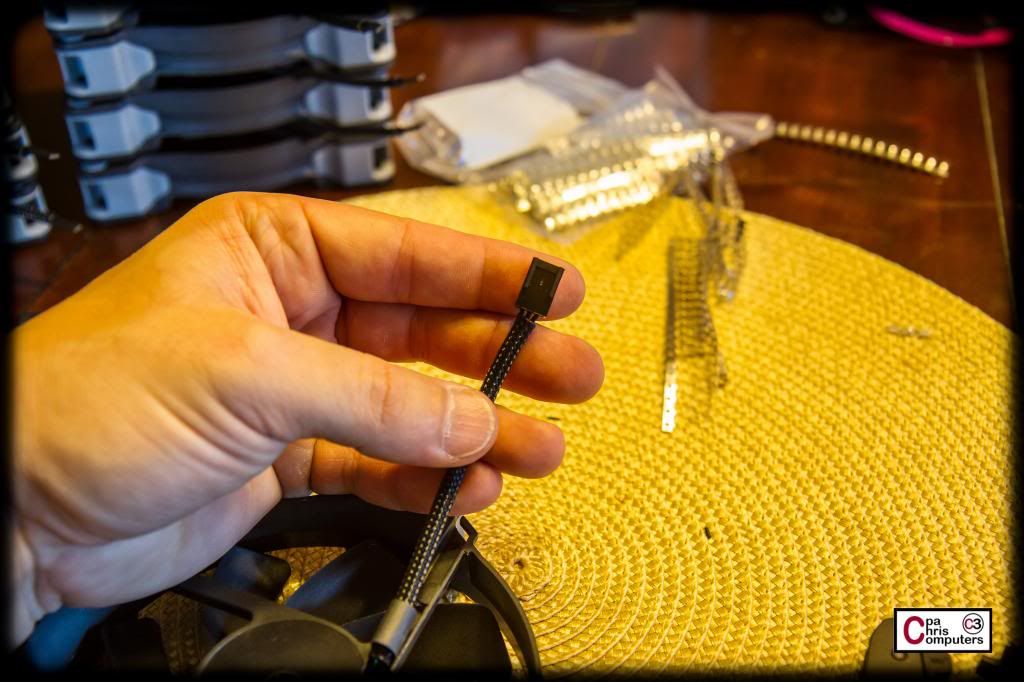
Then I slipped a connector on the terminals....
Rinse. Repeat. And now my stack looked like this.
Time to use the heatgun on that little piece of shrink I had initially put on down by the fan motor end of the cable. After this, I went ahead and tucked the sleeved cable underneath the plastic tabs on the frame....designed to hold the cable in place.
Rinse. Repeat. And now my stack looks like this.
Next, I needed some larger pieces of SATA size shrink for the connector end of the wire. Got out my jig again, adjusted the size, and used my scissors to quickly create just the right number of pieces.
Then I went ahead and slipped the shrink over the connector end of the wire, and applied some heat. The Lutro0 Customs shrink is really nice and shrunk down in a real nice way and looks very attractive.
Rinse. Repeat. And now my stack looks like this.
I'm done for the night.....but don't have much left for the fans. All I need to do is paint the accent rings pink, and then make the custom vinyl stickers. Should get to that this week.....
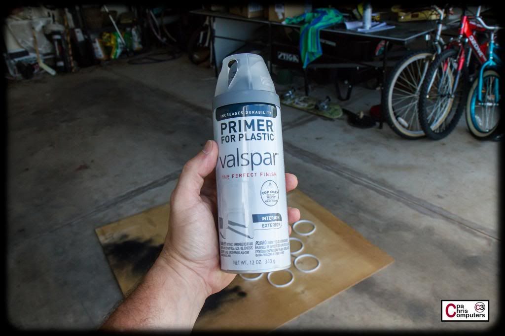
Did some work on painting the fan accent rings today.....
Started with two light coats of this plastic primer. About 15 minutes inbetween coats...and then waited about 2 hours before continuing on with the paint.
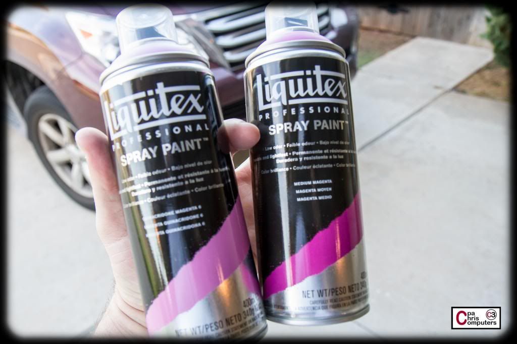
For the paint, I'm again using the Medium Magenta from Liquitex. If you are trying to match a certain color and need rattle cans....definitely look into Liquitex. Sold at Michael's. Tons of colors and the finish is incredible. I'm going to alternate coats between these two colors. The medium magenta is real close to my case color...but it gets a little dark when multiple coats are applied. To counteract this, I'm going to use a slightly lighter color inbetween my medium magenta coats.
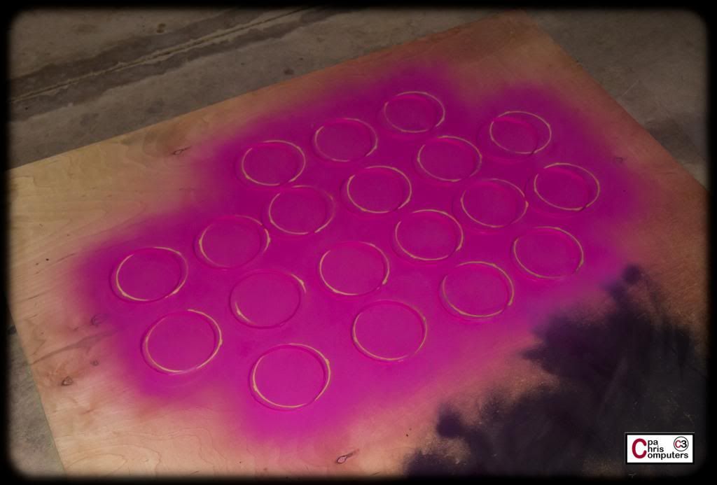
First coat of Medium Magenta....
Second coat of the lighter color (Magenta 6)....
...and a third and final coat of the Medium Magenta.
I'm going to let these dry overnight, and then I'll do a light coat of clear protection on top tomorrow.
Paint coats of magenta colors were also done with intervals of 15min ?
No....about an hour between the actual paint coats. Sorry, should have mentioned that.
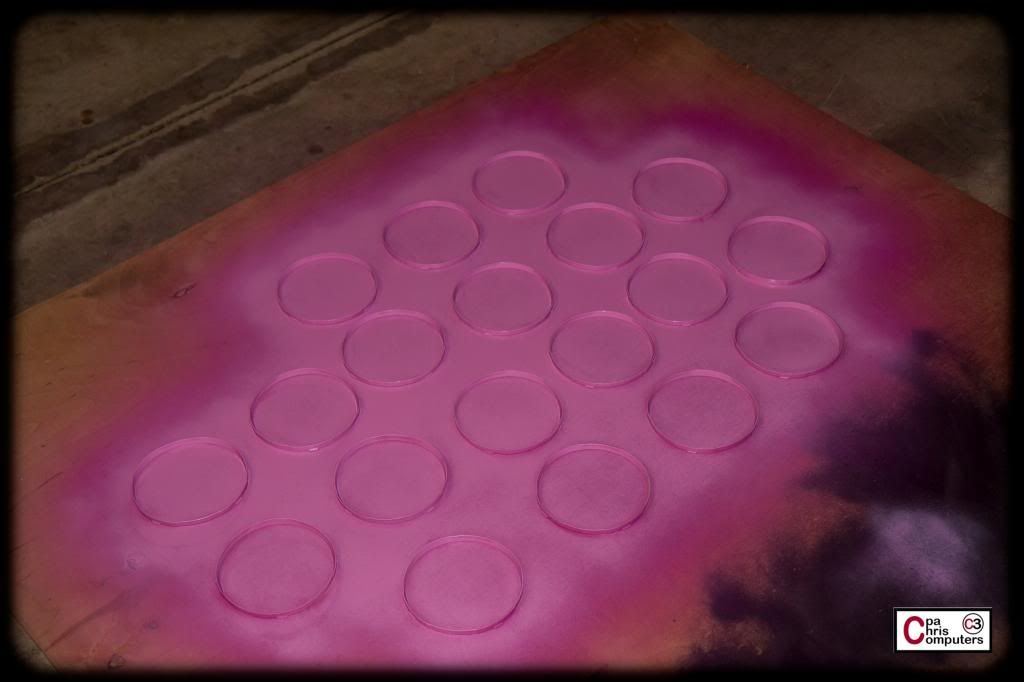
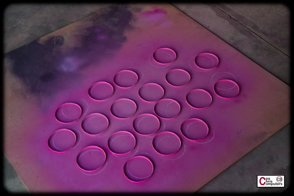
I did the first coat of sealer/protection this morning. Will do one more when I get home this evening. I'll do some studio pictures before I reattach all the fans to the rads.
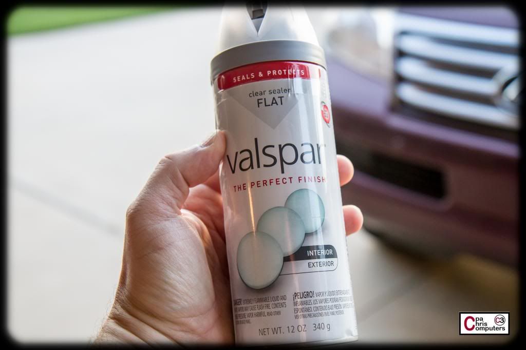
This is the sealer I put on this morning. Just one coat.
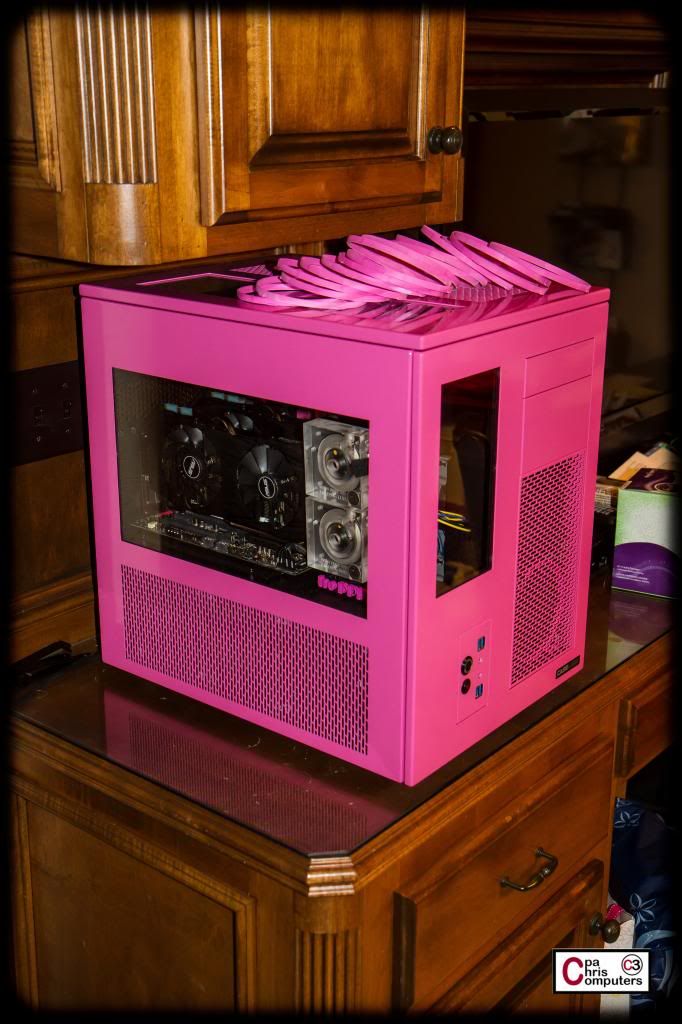
They looked pretty darn good out in the garage.....
....but I took some pictures of them on the computer so you could see how close the color match came. It's darn near perfect!
I was also quite pleased at how flexible the paint stayed. The rings have to flex a little bit to get them in and out of the fans. Since the Liquitex is acrylic paint in a spray can....it's finish is very flexible. Suffer through this short 7 second video for proof on the flexibility.
I'll finish up the custom vinyl stickers shortly....and then take some better shots of the finished fans.
 Posting Permissions


 Reply With Quote
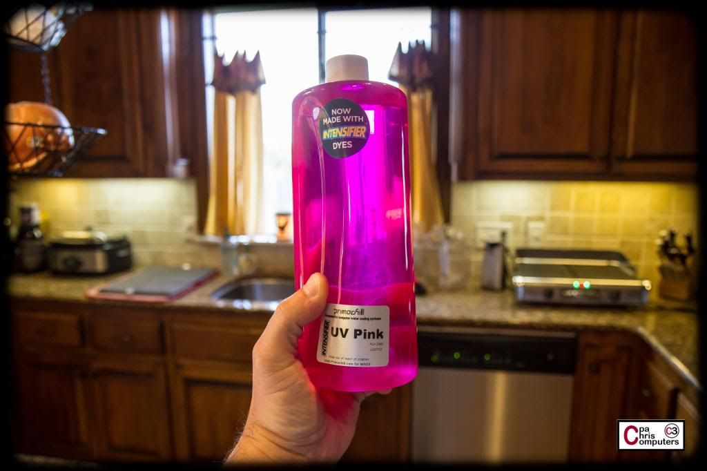


Bookmarks