

no cursing, when I said doing this i mean paying a sleever to sleeve my cables! :POriginally Posted by cpachris


no cursing, when I said doing this i mean paying a sleever to sleeve my cables! :P
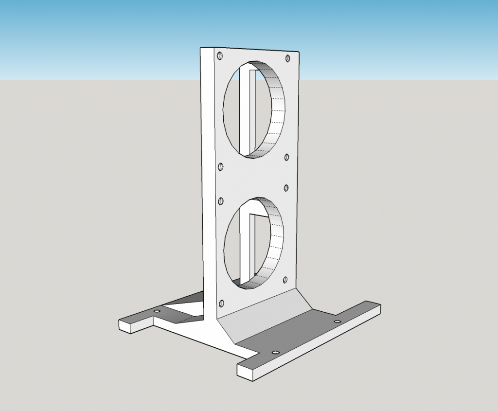
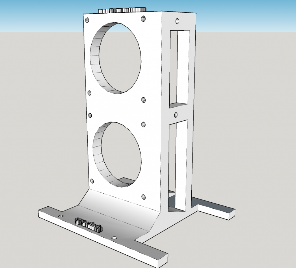
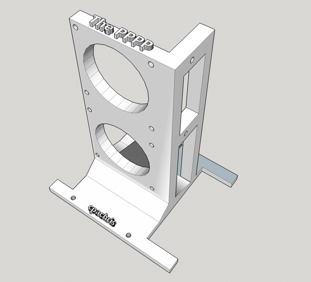
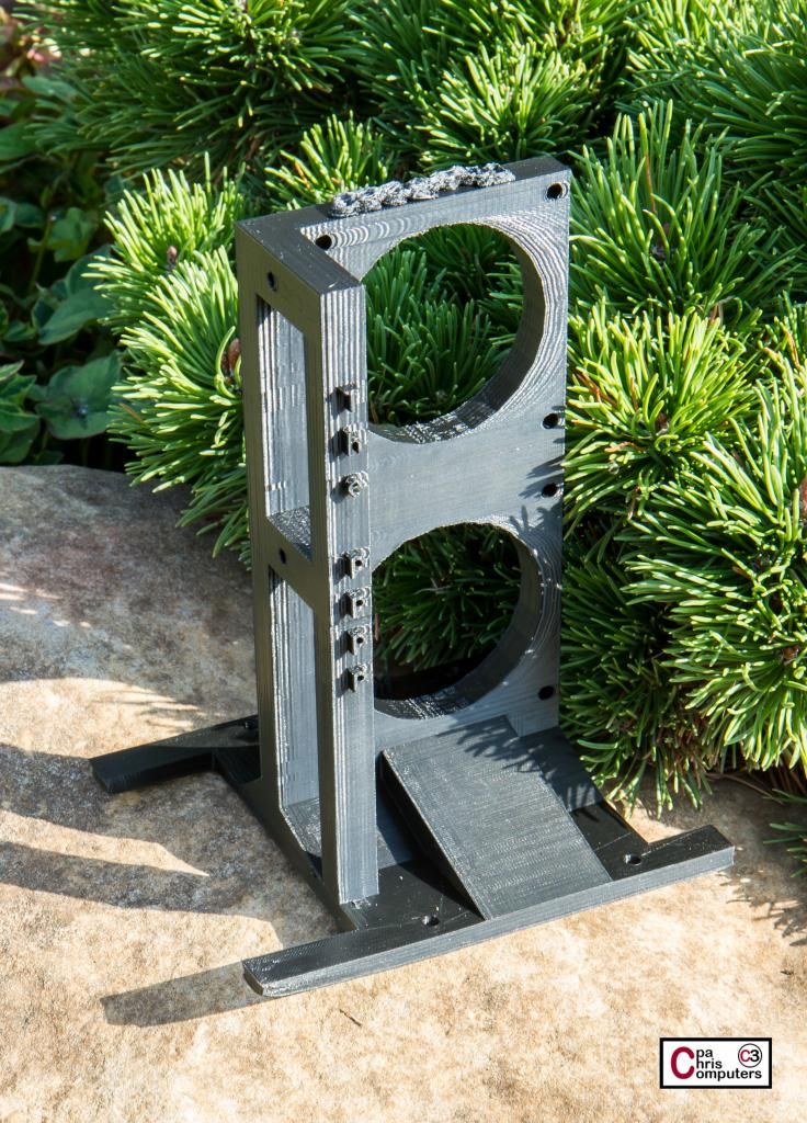
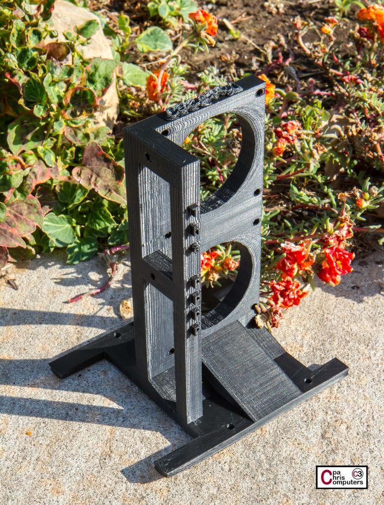
I'm back on the 3d printing design of the pump stand. For the next version that I actually send to be printed, I needed to add a mounting spot for the reservoir. I also wanted to make it a tad bit sturdier than the last version, so I'm going thicker, and I'll probably print it at 75% fill instead of 50% fill. See what you think of this design (views from all 4 sides below)....and offer me some ideas or suggestions that I could stick in before I send it to the printer......
You'll easily notice the extension over on the right of this picture. This is where I'll hang the reservoir. I don't have the holes in the design yet, but there will be holes in both of the horizontal bars, and the bars are positioned right where the brackets for the EK reservoir will be...
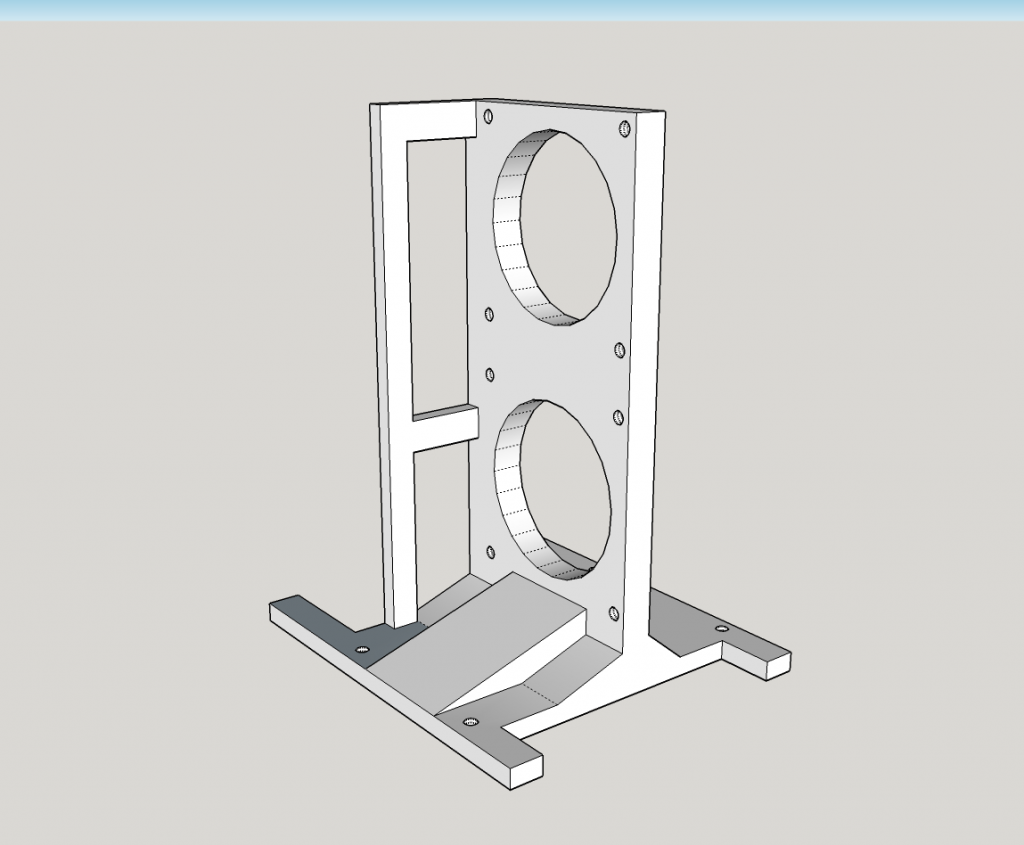
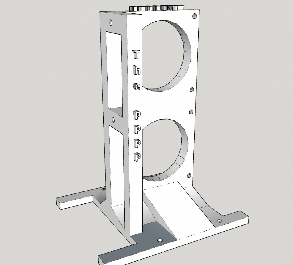
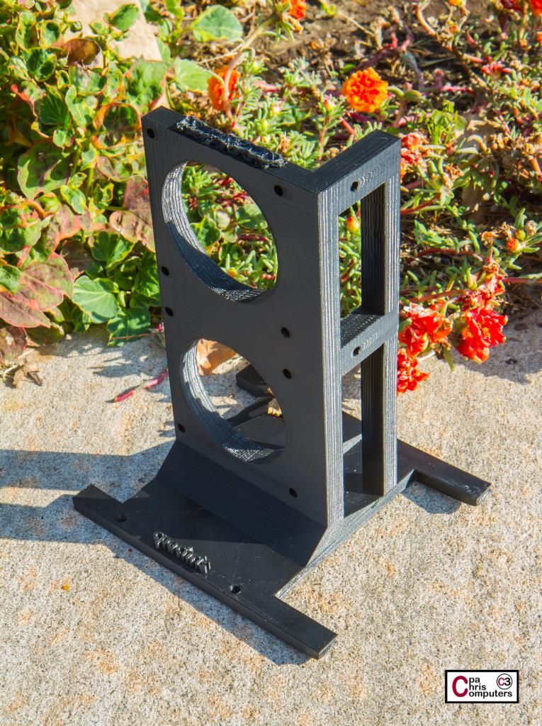
The reservoir will be positioned right in the middle of the front window of the case. The two legs that extend out from the pump stand are for more stability, but I've also designed the space in between the legs to be the exact width of 2x inverter boxes for the cold cathode lights I'm planning on using. I'm needed to utilize this space on the floor, because there is not a lot of extra space with all the windows my case has....
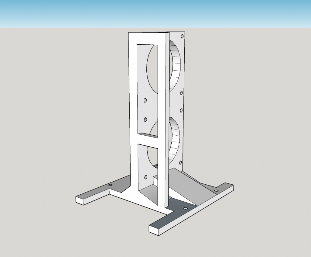
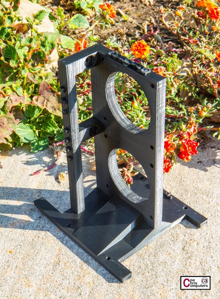
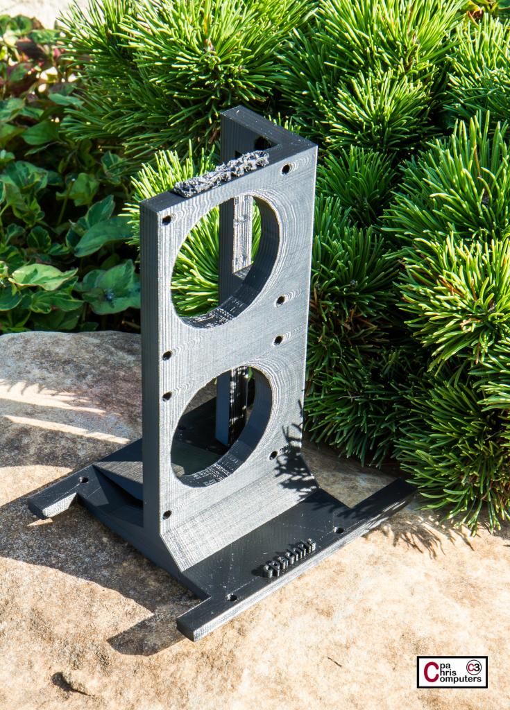
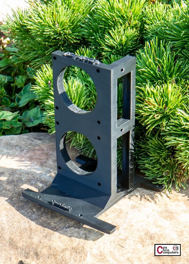
From this view (the back), you can see how I've built up a little more support at the base. It comes higher up the vertical plate, without interfering with the pump vibration dampners....
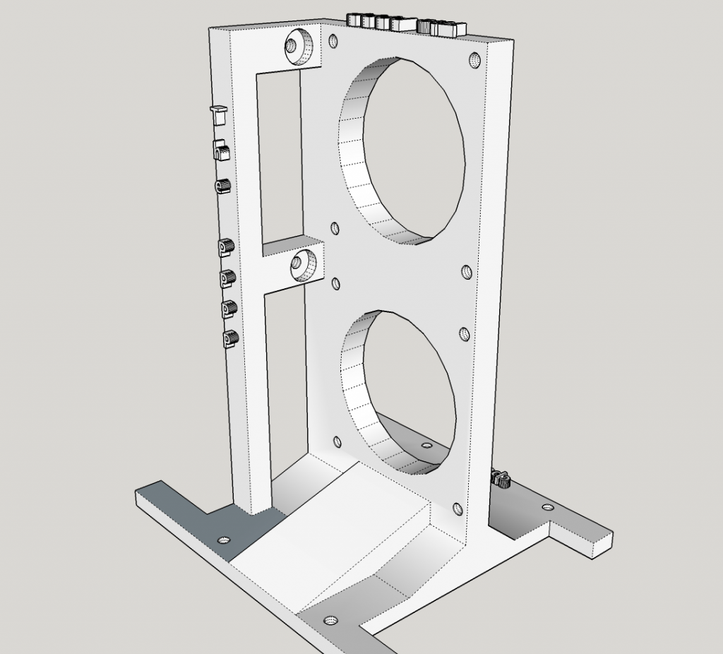
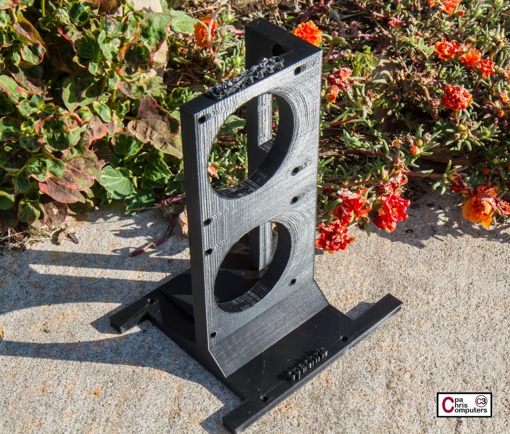
On this side, you'll see two legs that are extended much shorter than the ones on the other side. These will wrap around the cable management cutout that is right by the SATA connectors on the motherboard.
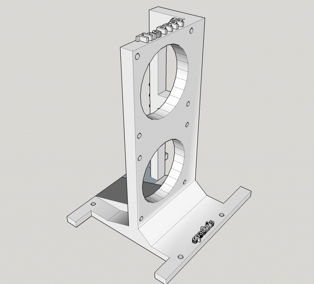
I'm finding it pretty easy to add/change/delete in Google Sketchup. Send me some cool ideas that I can incorporate before I print the next (and hopefully final) version of my pump bracket on the 3d printer!
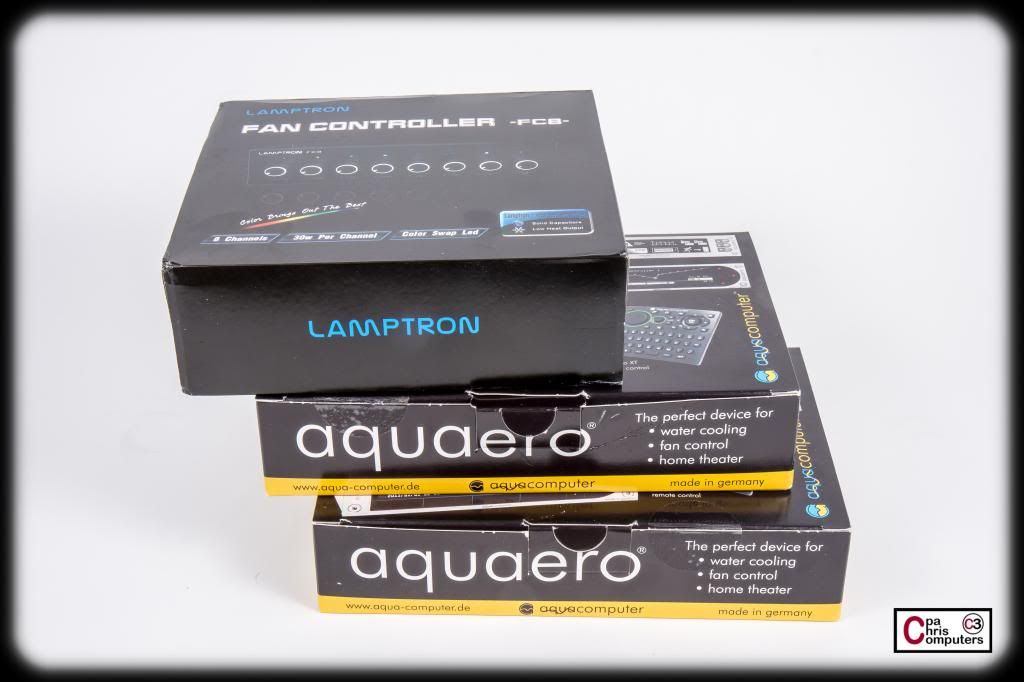
Here's the stuff I'm planning on putting in my Flex Bays. If I rotate the front 240 rad so that the ports are on the bottom, I'll have 3 flex bays to play with....
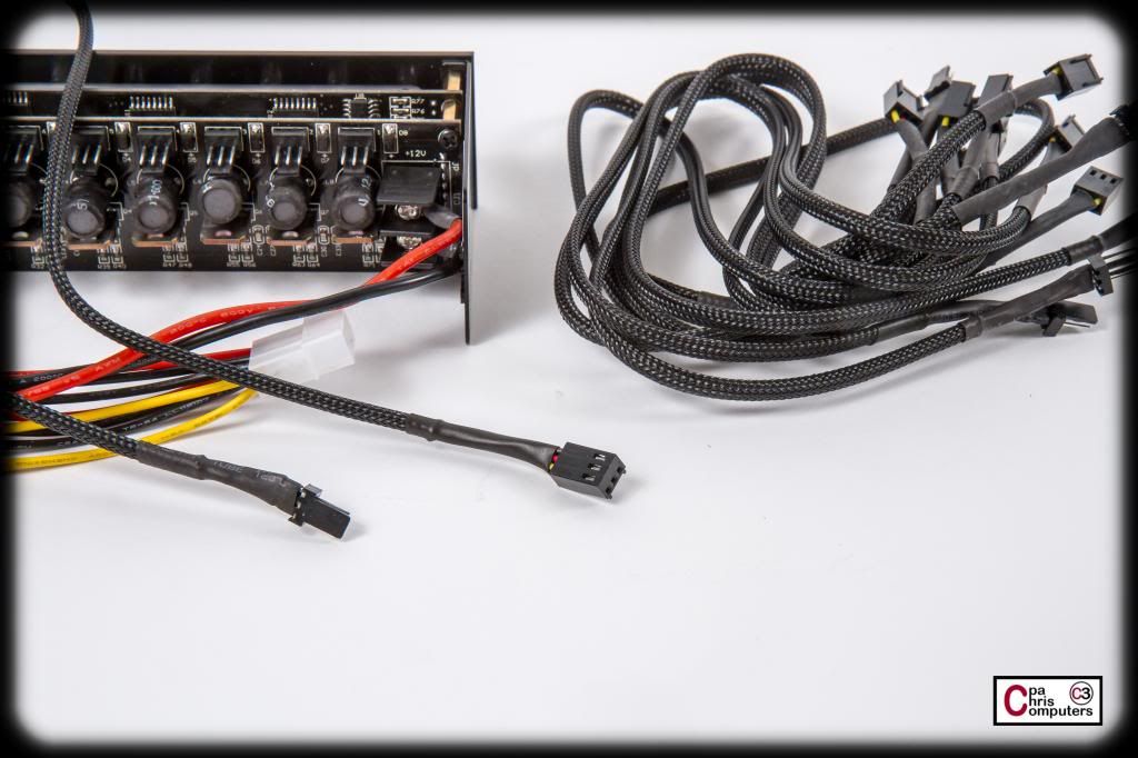
I've got an Aquaero 6 XT, Aquaero 5 LT and a Lamptron FC8 controller.....
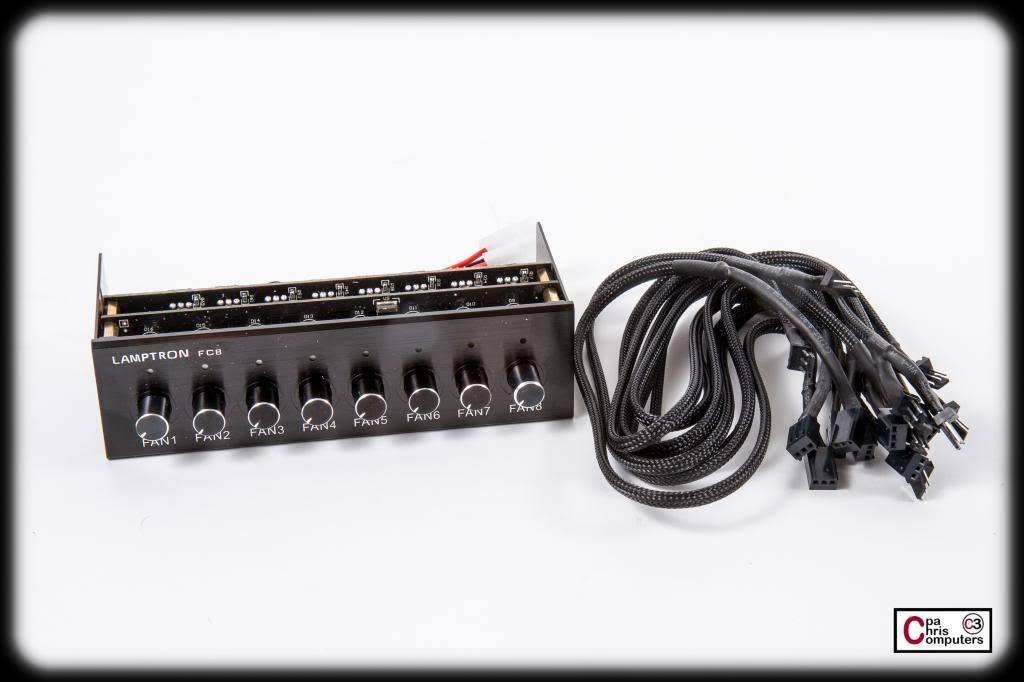
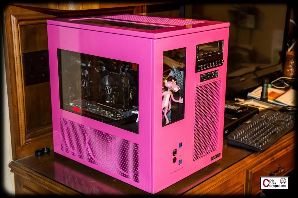
I used an FC8 in the BBBB, and although I don't think anyone would ever accuse Lamptron of top-notch quality, ....there are some features that I really like about the FC8. There is an LED indicator light above each channel to indicate whether it is on or not. The color of the LED light is customizable with just a few clicks of the buttons. And the "purple" LED light option looks pretty darn pink when next to this case. So it's like I have pink LED power indicators for the channels in this FC8. I think my baby will like that....
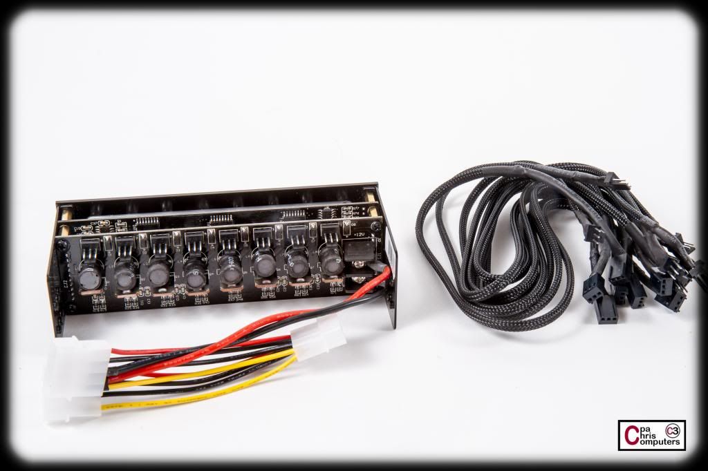
Here is the back....
It's been about 2 years since I purchased my last FC8....but when I did, none of the extensions were sleeved. This time around, Lamptron made a little effort and put some black sleeve on the extensions. Much nicer. I wouldn't call it great sleeve....and I don't like how long the heatshrink is close to the connector....but if someone wasn't going to take the time to sleeve these on their own...these look much nicer than the black, yellow and red wires that were showing on my last set of these. Now Lamptron....sleeve the power connectors and you'll have a nice looking product!
I'll still re-sleeve all of these in my black Telios sleeving. Plus, I'll get rid of the 3 molex power connectors and make something cleaner. I guess I can understand the need for 3 molex connectors if someone was going to run all 8 channels at 30 watts. That might be too much current for a single molex connection with small gauge wires. Maybe. But the Lamptron FC8 is going to be for controlling/dimming lighting. That's all. It won't ever handle too much wattage, so I should be fine with a sleeker power delivery system than this horrid 3 molex cable it comes with....
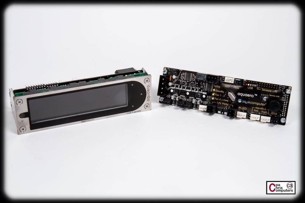
On the left is the Aquaero 6 XT and on the right is the Aquaero 5 LT. Plenty of pictures of these out there already....so I won't bore you with too many here. I'll probably treat each set of rad fans as a separate fan channel, so there are 3 channels there. Both pumps are voltage controlled, so there are 2 more channels there. Plus, there are a couple of exhaust fans on the back of the build. So it would have been almost impossible to get away with only the 4 channels available on the XT. I toyed with the idea of some PowerAdjust2's....but since I hadn't ever used an LT in slave mode before....I opted to go that route.
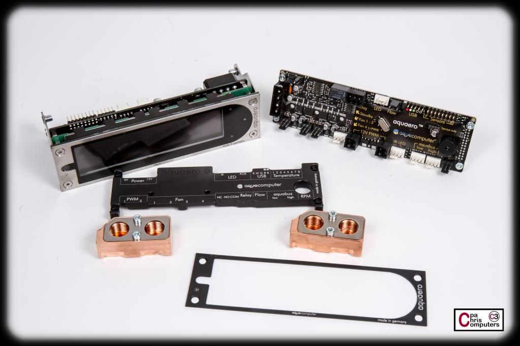
I did get a few accessories for them. The black passive heatsink is a naturally addition for this build. That bright red heatsink would have looked hideous in here, so I'm glad they came out with a black version. I also have waterblocks for both. May need to paint the outside of these black to keep with the theme. A hunk of copper in the middle of this build would ruin my mojo.
I also got an extra faceplate in black. I'll have to decide if a black or pink faceplate would look better. For the BBBB I had the faceplate powerdercoated crimson....and it looks awesome. May have to try an extra one in pink and see what that looks like.
I have high hopes for the new EK Ascendacy that I showed earlier in the thread. Beta testing is ongoing, and EK has knocked out a few software bugs already that were stopping many in our test group from being able to open the software application that goes with it. But I don't know if they will be ready with a retail version of the product in time for this build. I'll still have some screenshots and shots of the software later so you can get a better feel for how it compares with Aquasuite.
More soon!
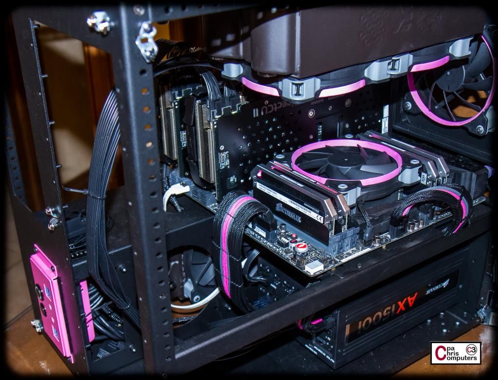
Doing some preliminary installation of the flex bay stuff today to see what it looks like. First off, to make everything easy to access, I removed the front 240 radiator mount. Love how this works on the CaseLabs S8. A few thumb screws and I can pop the whole thing off and remove it. Super easy.
I took this opportunity to rotate the fans so that the power connectors would line up on the inside of the case instead of the outside. I also turned the radiator so that the inlet/outlet are at the bottom of the case instead of the top. This way, I don't burn one of my few precious flex bays.....
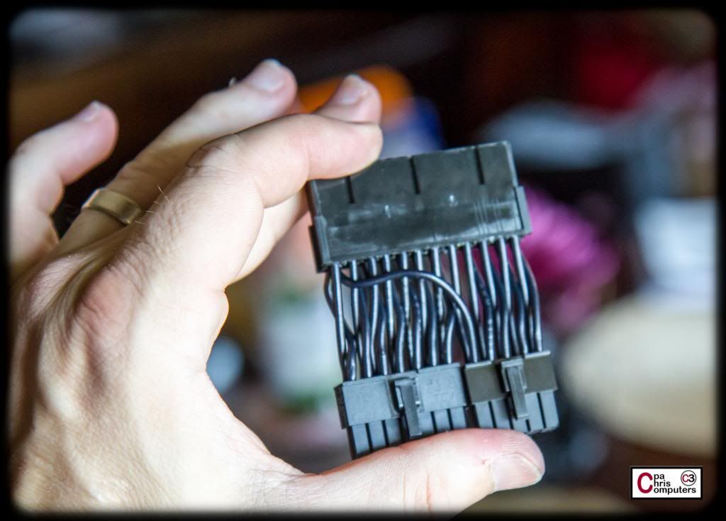
While I had the radiator mount out...I took a few shots. Easier to see the 24 pin cable with the radiator pulled out. Really need to get on the GPU cables though. They stick out like a sore thumb with the other cables done....
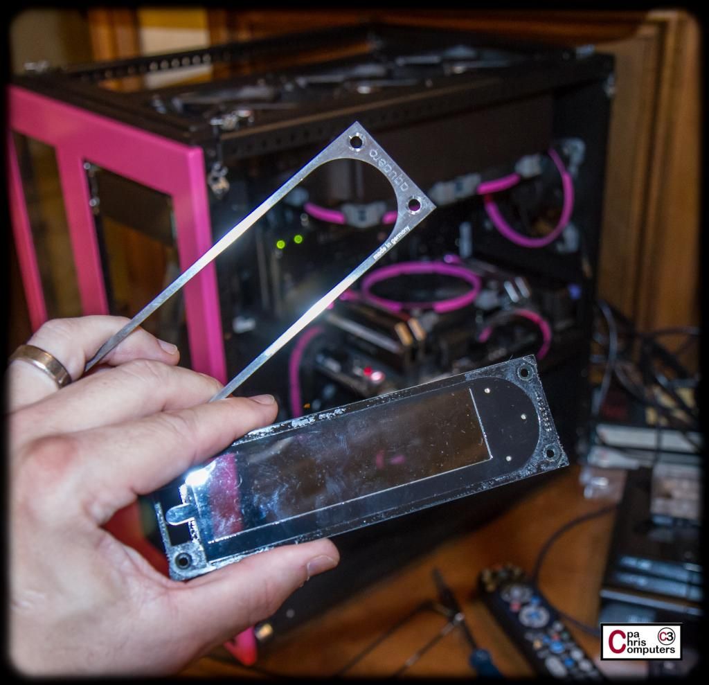
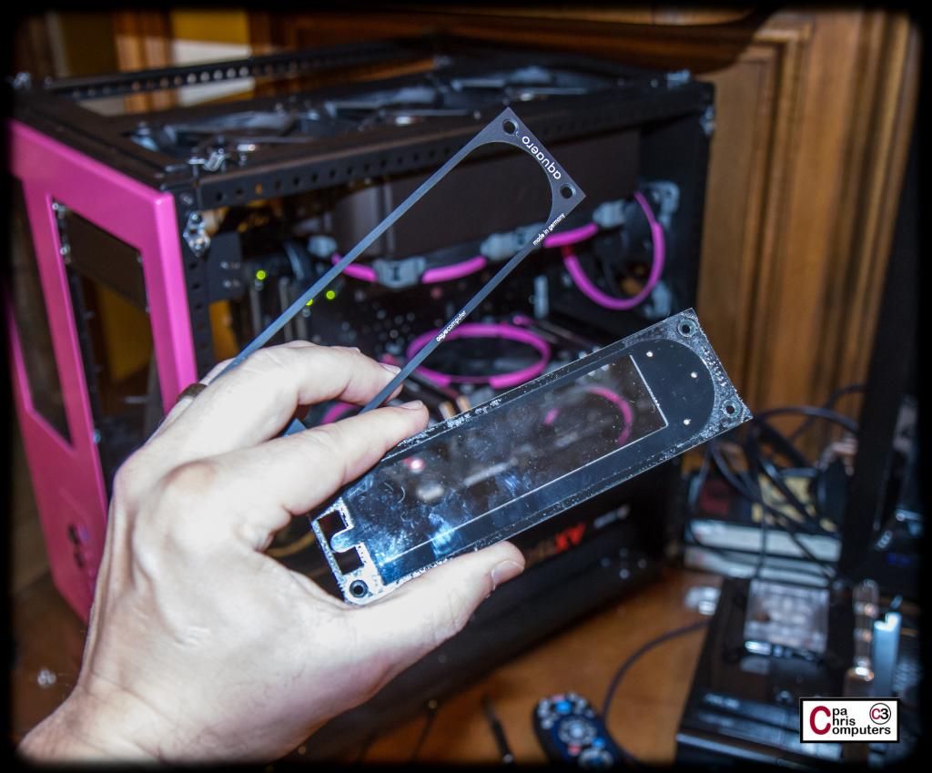
I got the Aquaero 6 XT out and pried the stainless steel face plate off the back of the face plate. It's just held on by some sticky.....
I replaced it with this black one that I picked up.....
....and then I put the Aquaero's and the Lamptron FC8 in the case. I think the black faceplates look pretty good! But I still think I'll get the extra Aquaero faceplate done in pink, and see which I like better....
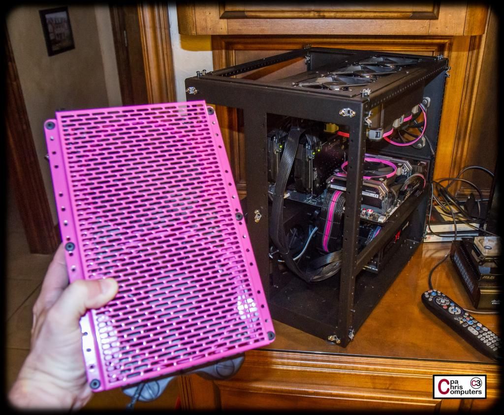
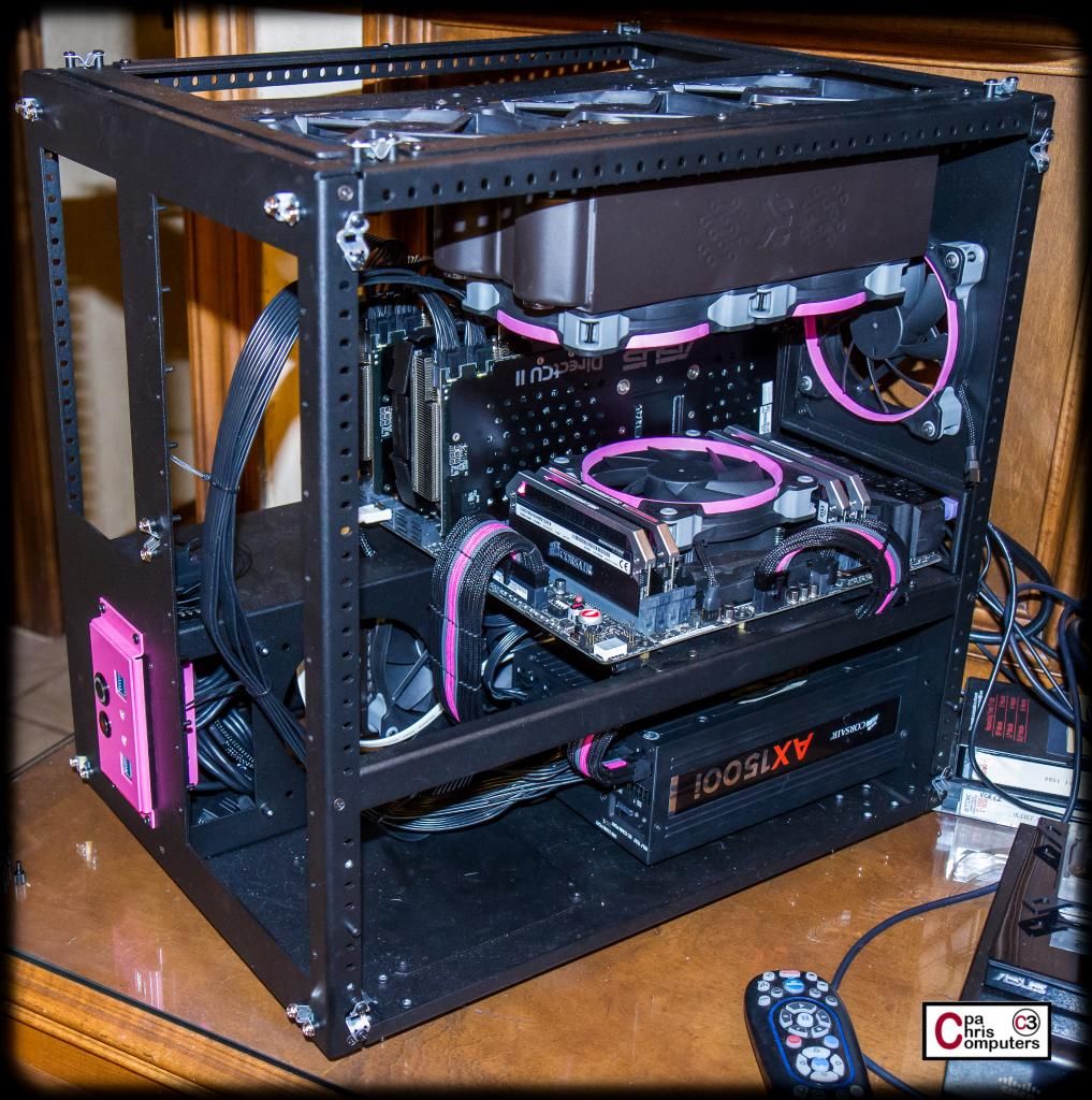
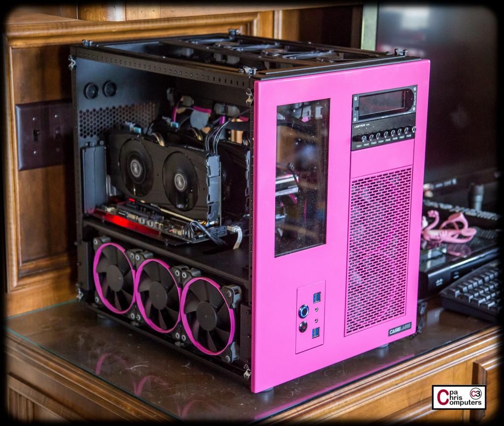
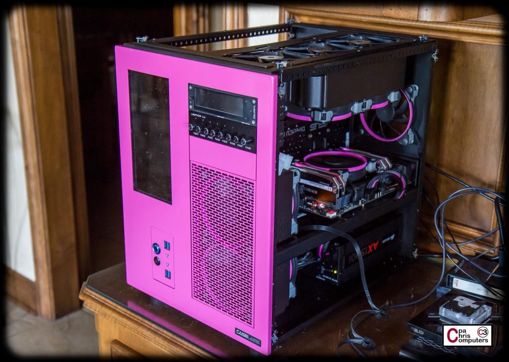
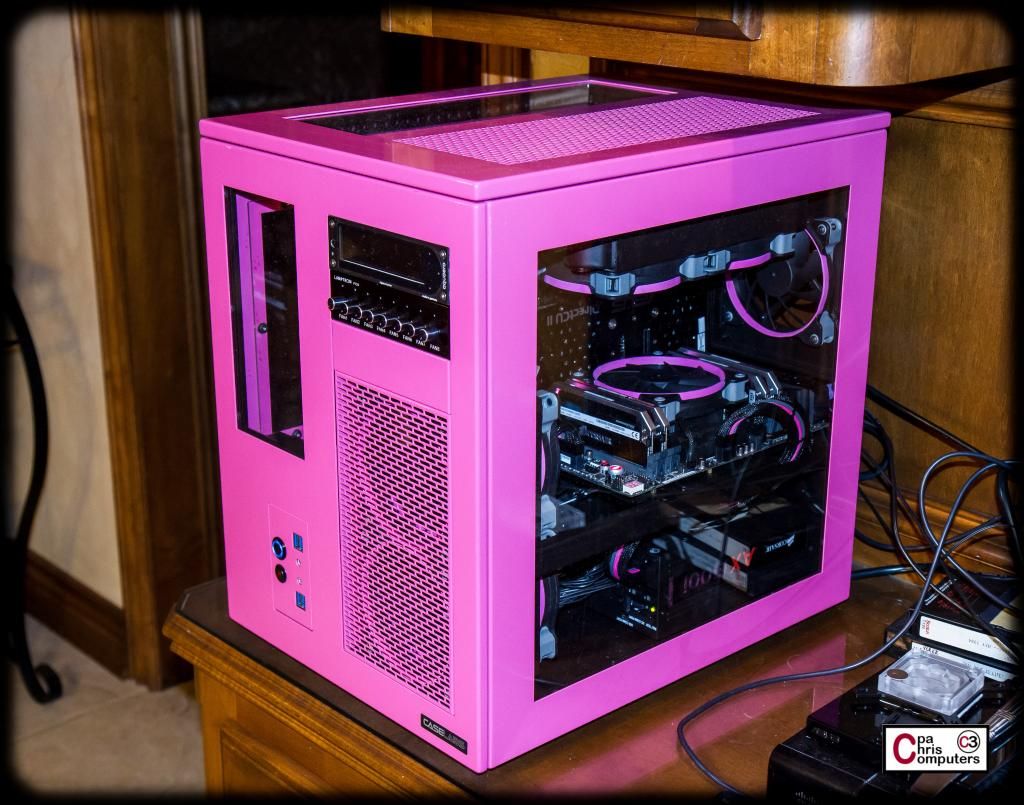
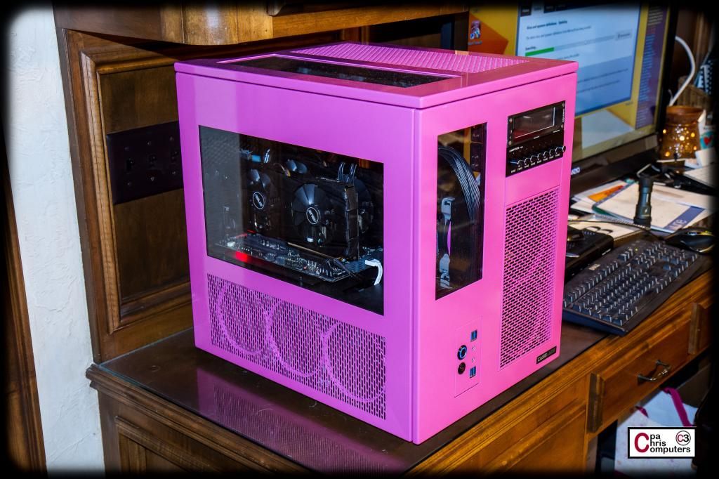
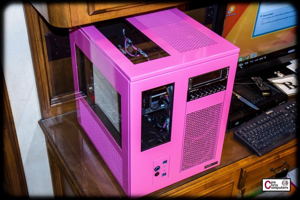
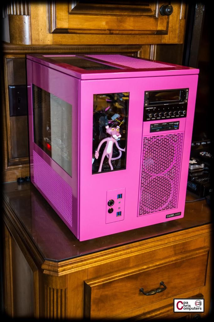
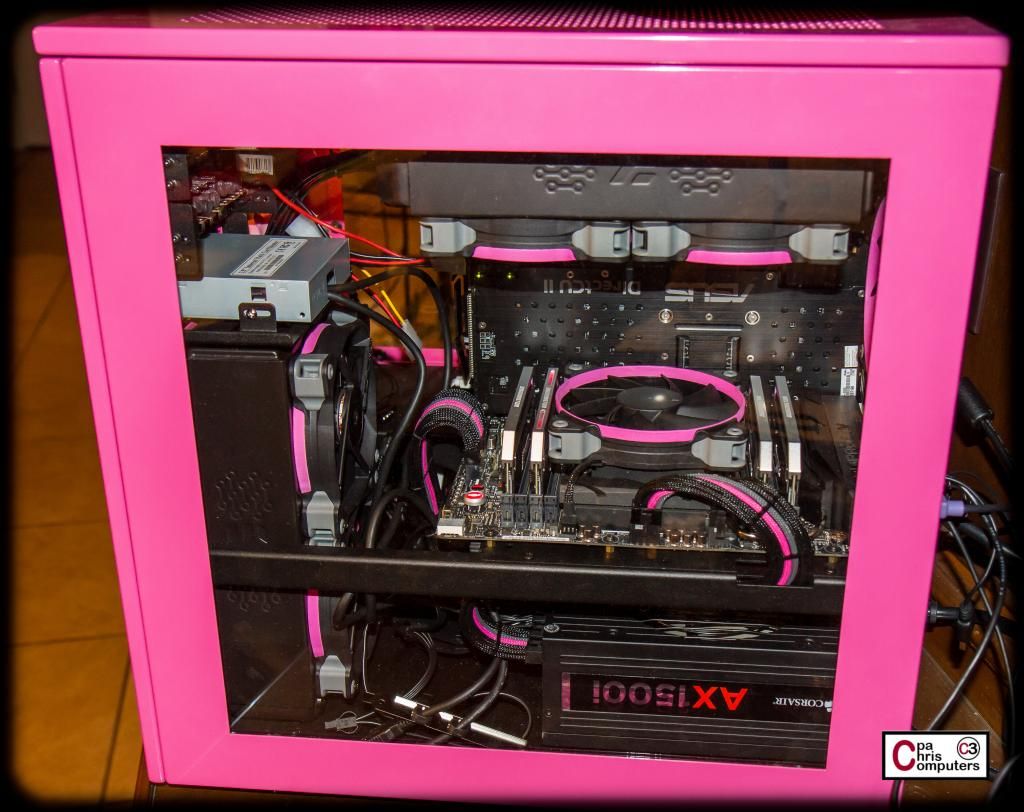
It's been awhile since I had it all suited up....so here are some shots with all the panels on.
I can't wait to see what it looks like with the dual pumps on the left side and the reservoir in the front window. More soon!
Front plates of controllers .. are not pink!
Are you suggesting they need to be pink? Or that they shouldn't be pink?
i was actually thinking if i wanted mine to match the case, and after seeing the black on pink (looks great) i think i may just keep controller black on my white case!
A dramatic reenactment of a conversation from a few days ago......
**************************************************
Me: Come check out the stuff I put in the flex bays!
Jenn: What are flex bays?
Me: ....just come look at the front of the computer.
Jenn: Awesome! Looks great! Where will I plug in the card from my camera?
Me: We can get an external card reader to plug in when you need it.
Jenn: You mean I can't just plug in my card to the computer?
Me: You can after you plug in the card reader to the computer.
Jenn: Why do I need to keep it separate?
Me: Limited space in the front of the computer.....
Jenn: So move something to the back of the computer....
Me: Like what?
Jenn: What is that blank spot there for?
Me: There is an Aquaero behind it. It will control your fans for you.
Jenn: Do I need to touch it?
Me: No. You can't touch it.
Jenn: Then move it to the back of the computer, and put a card reader in the front for me.
Me: But......but...... Ok.
************************************************** ***
My baby may not fully realize what she's getting....but she always knows what she wants. She's usually right about these things anyway.
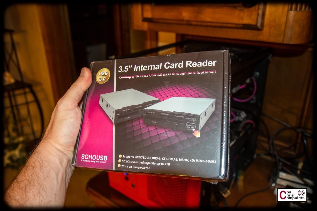
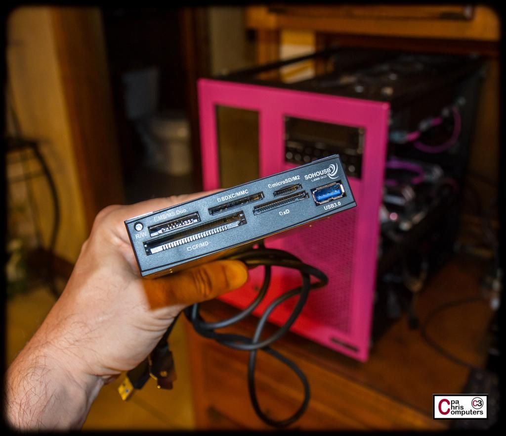
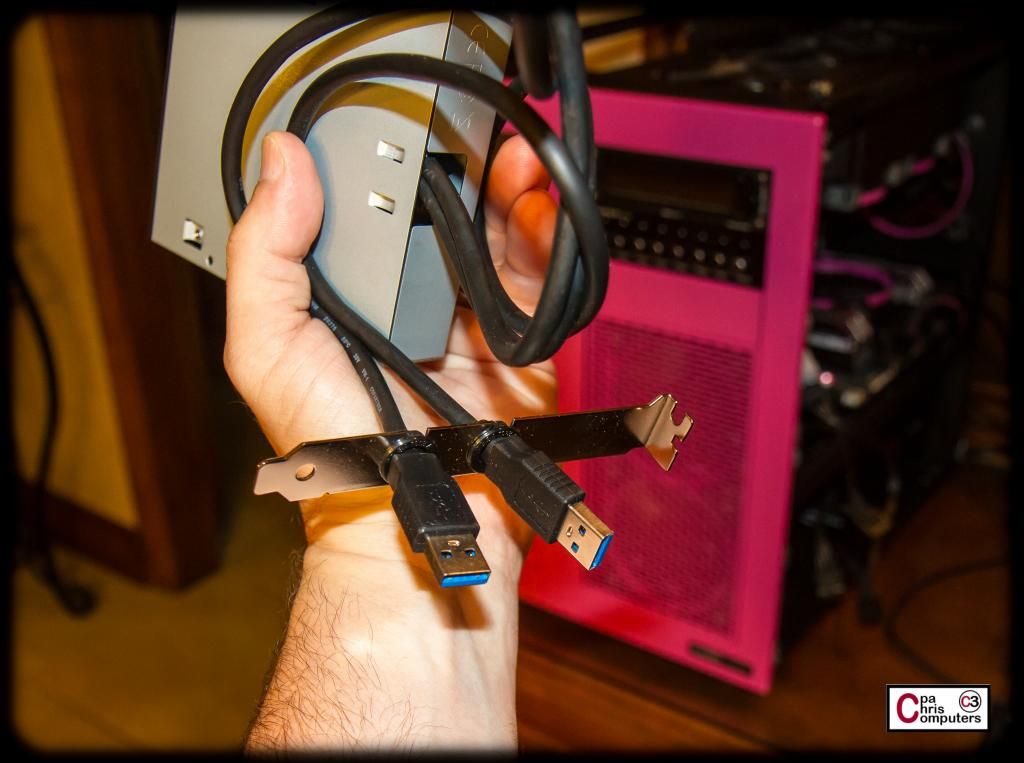
Here's the card reader I hastily ordered from Amazon to address the situation. Same one I used on the BBBB with good results......
My camera uses compact flash, and Jenn's uses SD, so this one covers both of us.
I'll hook up at least 2 of the CaseLabs USB ports on the front panel to the motherboard 20 pin. And probably both of these cables going out the back of the case will give Jenn at least 3 USB ports on the front of the case. May see if I think I can hook up the other two CaseLabs ports in a clean fashion....
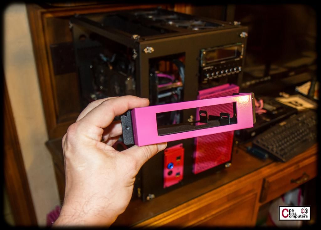
I already had one of the 3.5 inch adapters from my initial package of stuff from CaseLabs....
Fits perfect! I think I like the pink around the border. Makes me think I'll like the Aquaero with a pink faceplate....
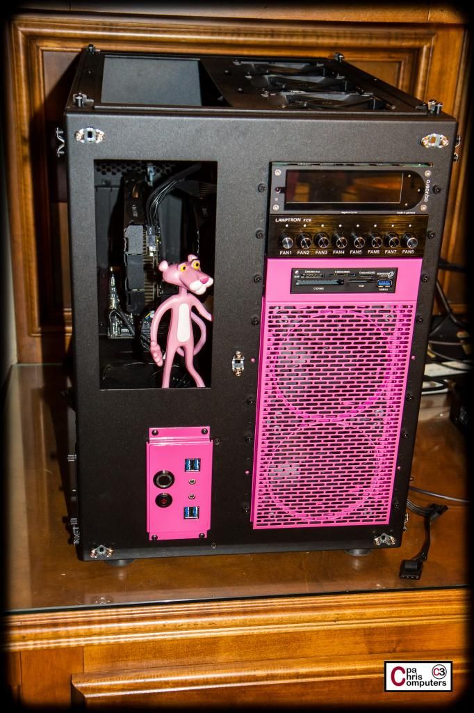
Here it is with the panels on....
But....that dull grey box is ruining my mojo....
Definitely going to have to paint or powdercoat the housing for the card reader....but I do like how it comes out just about even with the radiator. Doesn't stick out too far....
Still playing with alternate locations for the Aquaero LT that was displaced by the late discovered need for a card reader!
Finished up what I hope are the final 3d printing design changes for the pump stand, and I have it sent off to the 3d printing club that I have an "in" with. Not huge changes from last iteration I showed off here in the build log....but I made a few.
From the angle below, you can see the holes I positioned for mounting the EK Res X3. They are positioned so that the brackets included with the reservoir should be at the very top and bottom of the reservoir.
From this angle you can see what I'm doing with lettering for this final version. The way I had the lettering positioned before really wasn't very visible from the angles people would be looking at the computer most often. No one would ever be sitting down on that side of the computer....only standing. So the downward viewing angle lends itself to lettering laid out flat on the mounting bracket, instead of standing up. You should be able to see this lettering from a downward angle on the side window....as well as from the top window.
This lettering on the back of the pump stand should be visible from the main sitting position while using the computer. You would see it looking through the right side window....
I hollowed out a larger hole that doesn't go all the way through for the reservoir mounting bracket. It became apparent that the nut would interfere with the pump mounting mechanism if it extended beyond the vertical plane of the bracket....so I needed to recess the nuts into the bracket.
....and one final angle....
Designing a custom part for this computer has been fun. I'm a first timer with 3d printing. But it is just downright cool to be able to come up with a vision of what you need for the build.....and then "print it". Once I've heard when the 3d print will run, I'll keep you updated. Non-members typically only get print time on weekends....and then only when members are not using the printer.
I'm still deadly serious about trying to start a 3d printing club for computer forum members, where we all collectively purchase a 3d printer. More info on that soon.....
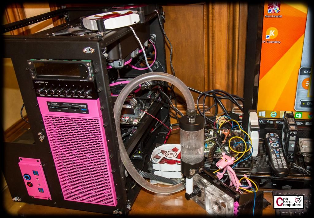
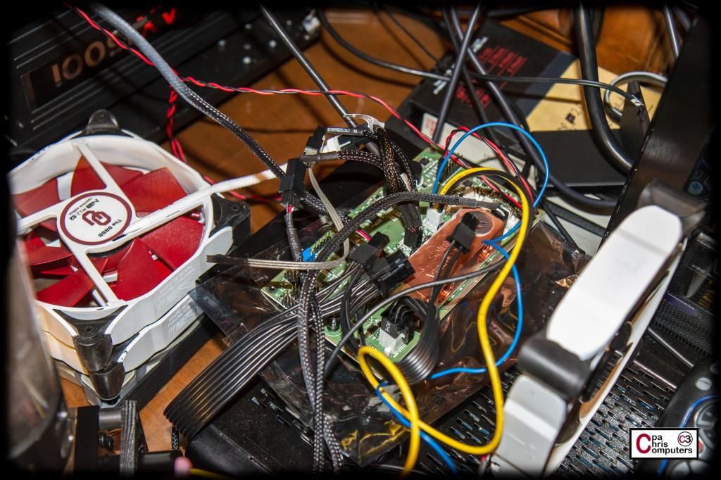
Finally had a chance to use the latest iteration of the EK Ascendacy software yesterday. EK was on it's 6th iteration of the software trying to solve an issue that most of us in the beta group were having when trying to run the application. They fixed the issue, and I can now use the software (and thus the hardware) for the first time. Don't laugh...but my quick setup is shown below. I hooked up one of my voltage controlled D5's and 9 fans.
You can barely see the Ascendacy tucked in there among all the cables, but it's there....
I'm going to do a little bit of walking through the screen shots on the system to give those that care a look at how it's setup. At the end of the post, I'll summarize my likes/dislikes about the current state of the software/hardware.
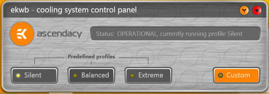
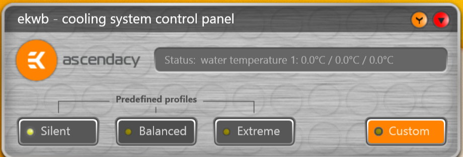
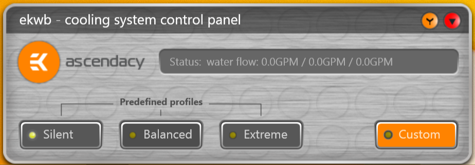
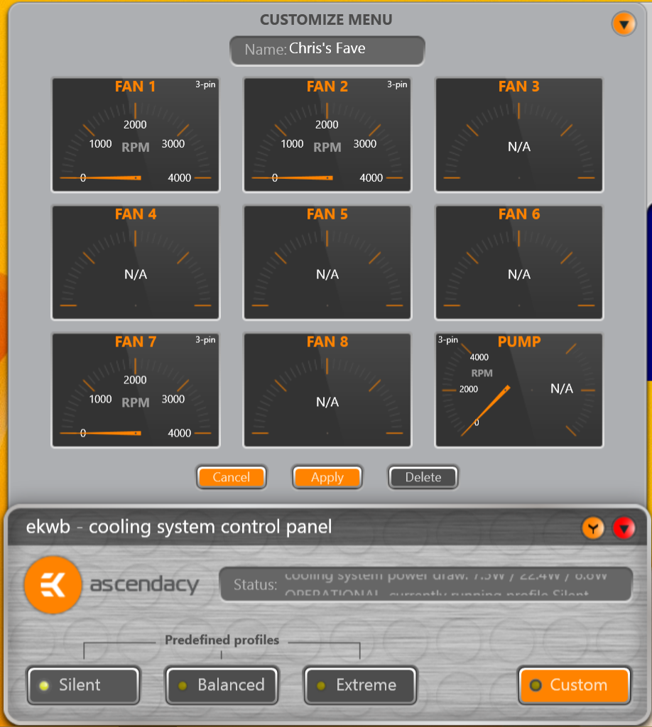
One of the best parts of the Ascendacy software is this little status box. It's really the hub of the entire application, and everything can be launched/accessed from here. It's main function is to allow quick switching between profiles, and access to more detailed screens when desired. The long thin grey text box that is kind of in the middle keeps switching between different pieces of information. Such as which profile you are currently running...
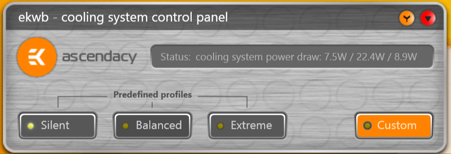
...how much power your cooling setup is currently drawing (fans and pumps, assuming you have the ascendacy powering everything)
...water temperature....
...and flow rate....
The information is OK....but it's really the profile buttons that make this little screen so useful. I'll preface my comparison to the Aquasuite controls with the caveat that I'm still running version 2013-2 of Aquasuite, and things may have changed. But for the Aquasuite, if I want to load a different profile, I have to have first 'exported' that profile and saved the file in a location that I can find later. And then to load a new profile, I have to use the file/open dialog box and find that previously saved profile. And....I've had issues with custom fan/sensor names getting truncated and/or lost on profile changes.
These little buttons making switching profiles effortless. One click....and you're done. There are always times when I just want everything to spin as slow as possible, or as fast as possible.....regardless of what my detailed control curves are setup to do. EK really hit a home run with how simple they have made this type of process.
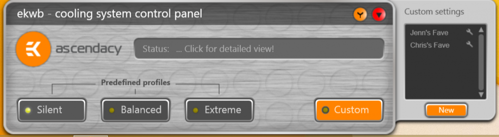
There are 3 predefined profiles. The 'Silent' profile runs everything undervolted. It reported it was giving all my stuff about 7.2 volts when I chose the Silent profile. Balanced was about 10 volts, and Extreme was the full 12 volts for everything. You will also notice the 'Custom' profile button to the far right of the screen. When you click this button you get a fly-out box that shows you all the custom profiles you have created. You can simply click one of these from the fly-out screen to select it. Very elegantly done.
Before I move on to some more screens, I will say that this little widget/control box really takes up far too much screen real estate on an 1080p screen. I'd like for it to be smaller, and I'd like the option to make it vertical instead of horizontal. EK...if you need to give up some of the status window to make it smaller....do so. The beauty of this screen/widget...is the quick switching between profiles. Also, I would give users the ability to pick one piece of information they want shown and leave it static. I don't always want to wait through 5 screens of info I don't care about to get to the one piece that I want to know about.
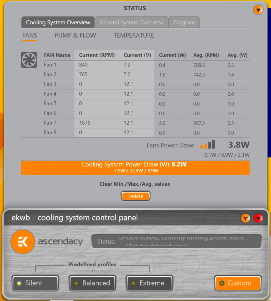
Moving on. When you double click the grey status text box on the main screen....you get a fly-out window up above it that provides much more detailed information about your cooling system. It's laid out very nicely and intuitively. It's got 3 tabs across the top. The first tab is 'Cooling System Overview'. Each of these 3 main tabs also has subtabs that show up right underneath the tabs. On the 'Cooling System Overview' tab, we have subtabs for 1) Fans, 2) Pumps and Flow, and 3) Temperatures. The first subtab (Fans) looks like this....
It's fairly intuitive and doesn't need much explanation. Fans 1 and 2 are the voltage controlled connections, and 3 through 8 are the six PWM connections. You can use the PWM connections to plug in non-PWM fans...but you will be limited to simply On/Off capability. However, you can use one of the sensor values to trigger the On/Off switch. But...you can't control the speed at all. It's either 100% or nothing. I'll also note there that even though you have the option to customize the name of your fans in the custom profiles....this screen here doesn't update at all with the custom names. It always just shows 'Fan1', etc. Lame.
I also am not sure what the light grey shading is supposed to represent. It would make sense if it were supposed to cover all the 'current' values to help easily identify them....but the 3rd 'current' column (Current Watts) is not included in the light grey shading. Not sure what they were trying to do here. I'll ask.
I like how below the list of the individual fans, they show the total power draw for all the fans. The fans I had hooked up to these 3 channels were drawing 3.8 watts when I did this screen shot. That's pretty cool. Also, the min/max/avg values are shown right below that. Nice. And in the orange box EK is showing the power draw for the entire cooling system (pumps included). I like how simple they are making it to get totals for all cooling system components. Very nice.
The orange 'Delete' button just resets the min/max/avg calculations. It was a little scary to press it the first time. Probably should be re-labeled to something more like 'Reset' or 'Clear'. Not 'Delete'.
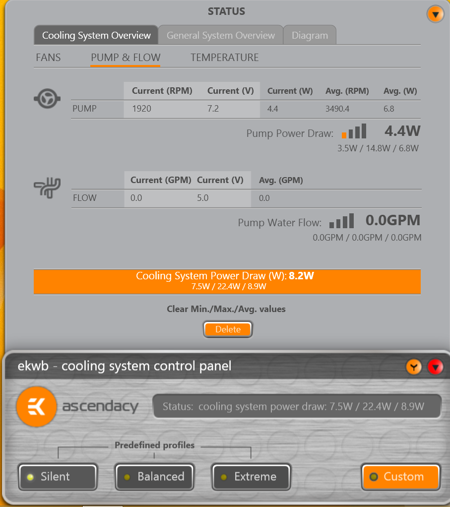
The second subtab...for Pumps and Flow looks like this.....
Very similar information to that which was shown for fans.
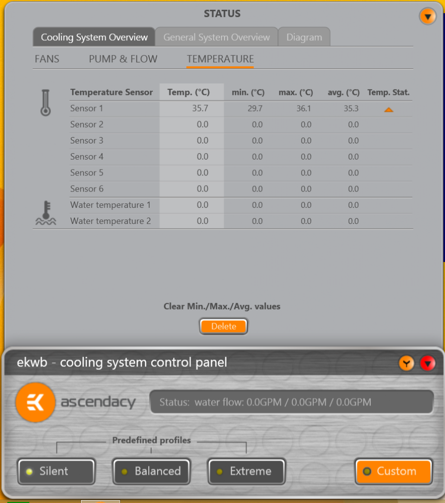
The third subtab for Temperature looks like this....
You can plug in up to 8 temperature sensors to the EK Ascendacy board. The last two locations are hard labeled as water temps....so make sure and plug in your water sensors to these spots. You can't rename the sensors either....so you'll have to remember that Sensor 3 was the one that you ran back to your memory sticks. Lame.
Also, on this screen the light grey shading is only around the current values. I think this is probably what was intended for the Fans subtab and the Pumps and Flow subtab also.
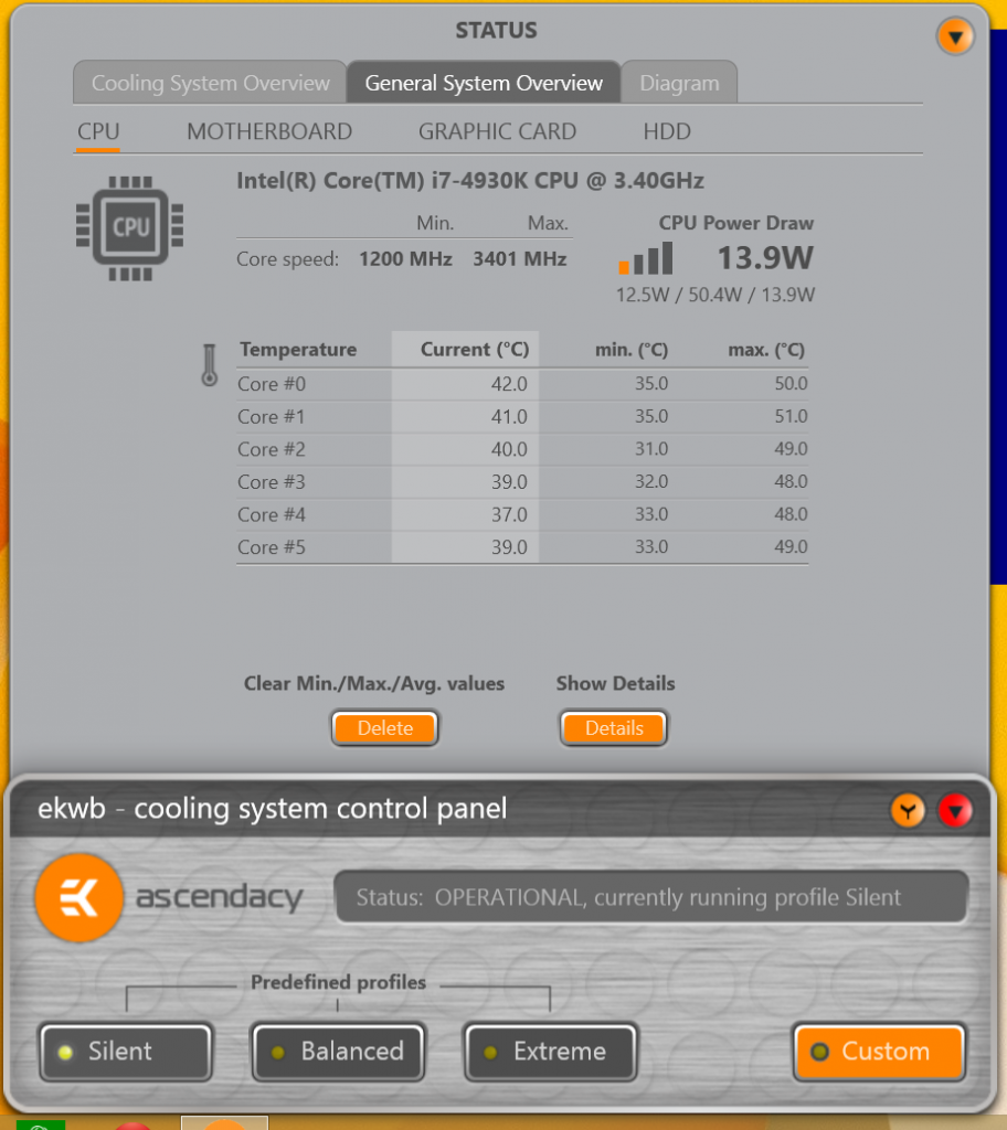
Moving on to the second main tab....'General System Overview'. This tab has 4 subtabs, including 1) CPU, 2) Motherboard, 3) Graphics Card, and 4) HDD.
The first subtab, CPU, looks like this:
It shows speed, temps and power draw. Well laid out. Easy to understand.
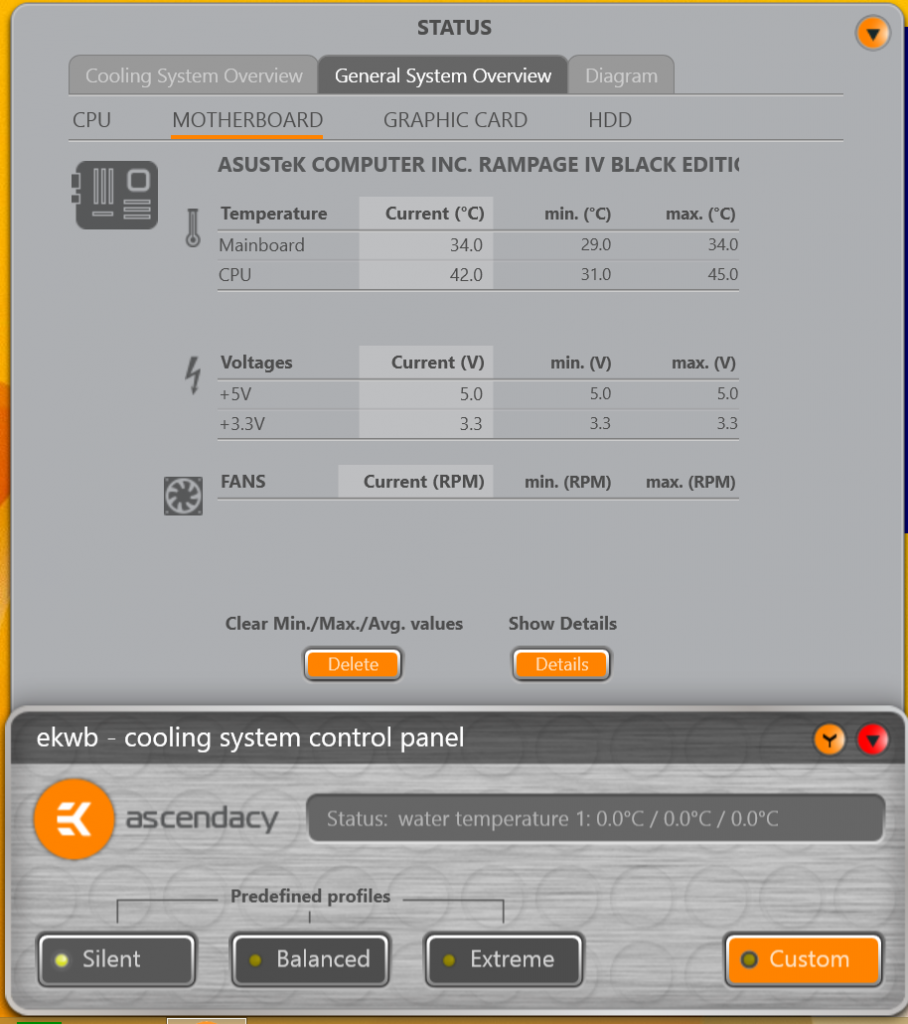
The next subtab is for the motherboard.....
It shows temps, voltages and details for any fans that are powered by the motherboard fan headers. Simple.
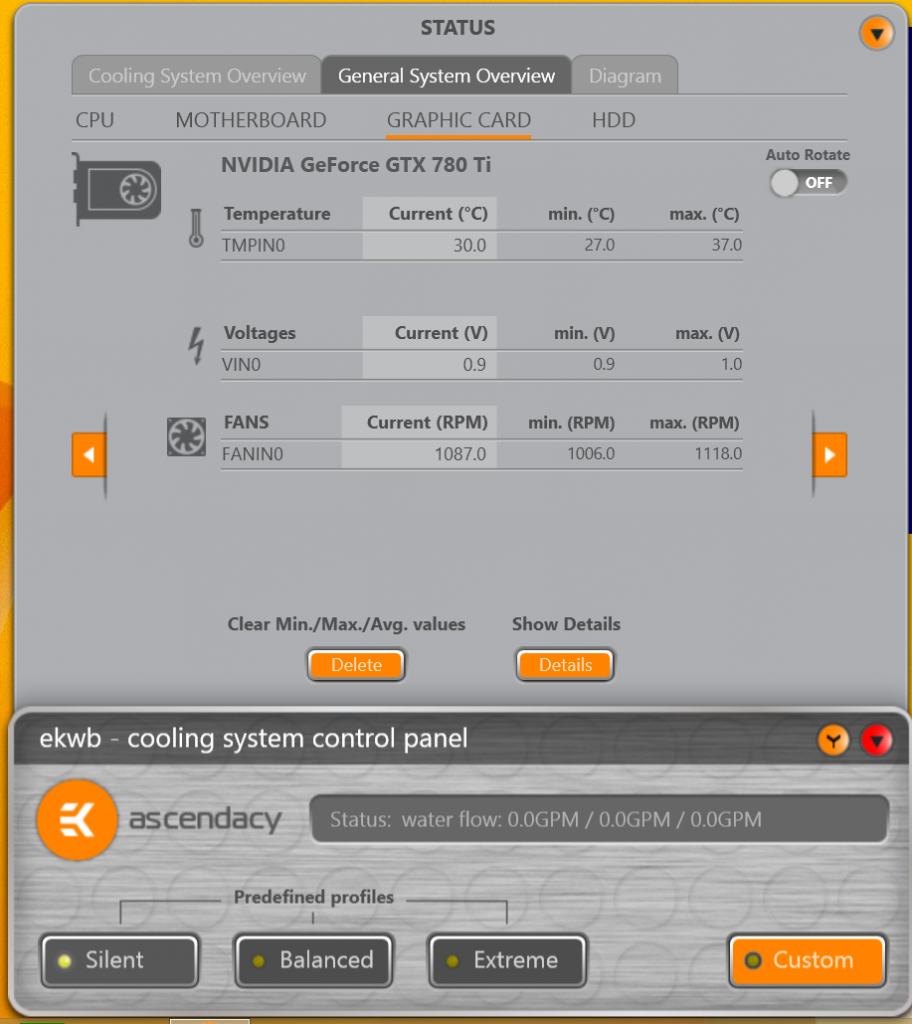
Next subtab is for the Graphics Cards.
It shows identical information that was shown for the motherboard. The one comment I'll make here...is that both of my graphics cards were identified with the exact same name and no number identifier. I figured out that the orange arrows on the sides of the screen must be cycling through any graphics cards it finds...because I could see the temps change when I would click the arrow. But without the card being identified with a number.... I had no idea which card was which.
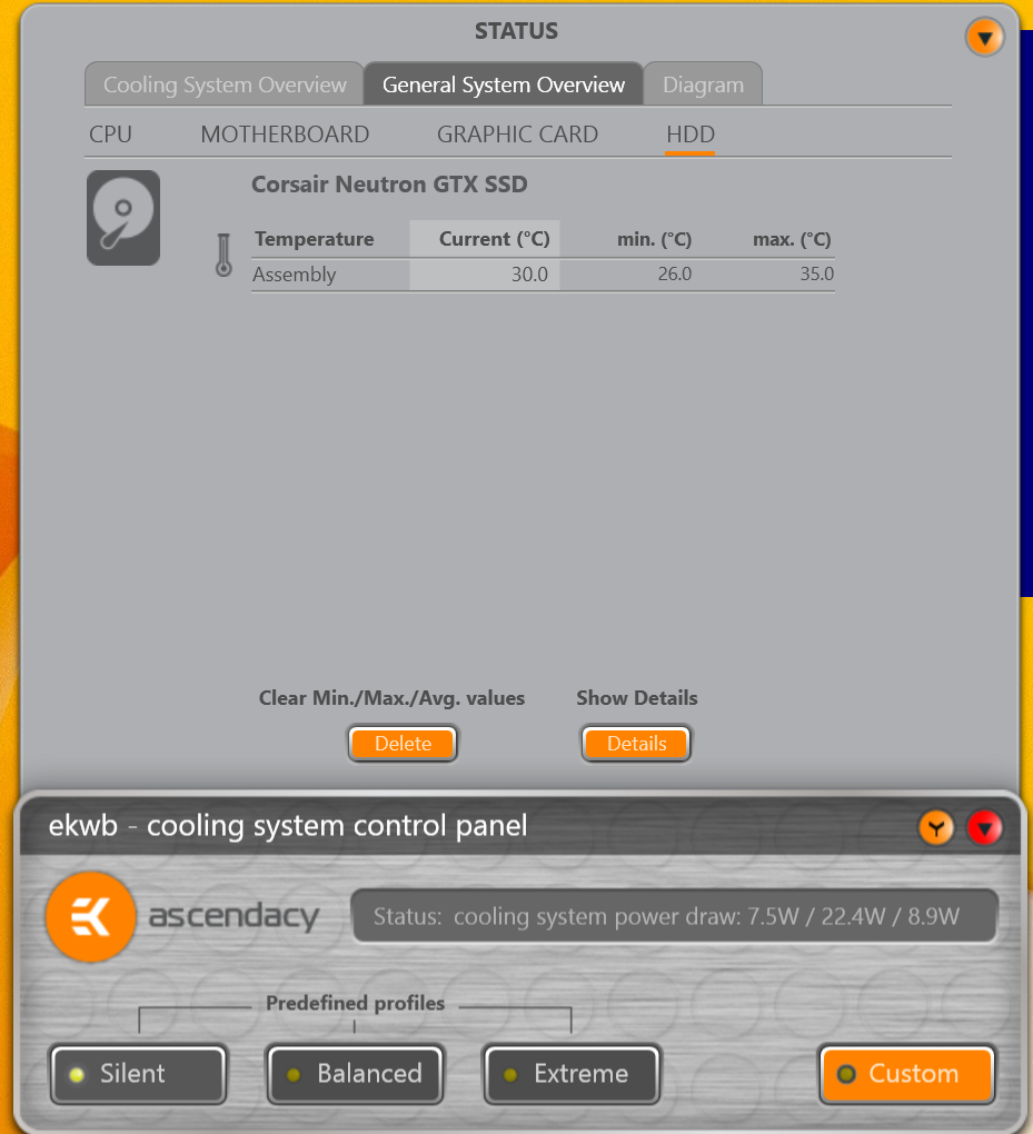
Next subtab is for the HDD's.
Just temps for the HDD's.
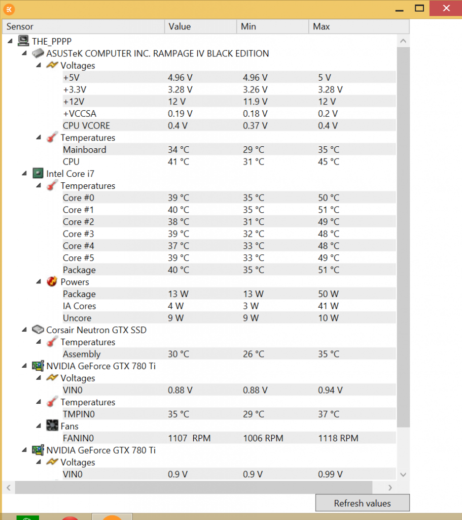
You may have noticed that orange button on all the screens that says 'Details'. Clicking this button on any of the 4 subtabs just brings up a larger window that has all the information on these 4 subtabs in one large window. Like this....
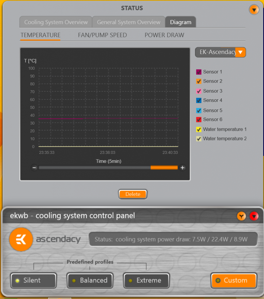
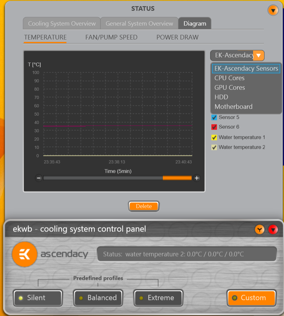
Time to move on to the 'Diagram' main tab. I would probably suggest EK relabel this as 'Charts', which I think is more descriptive of what it is than 'diagrams'. The Diagram tab has subtabs for 1) Temperatures, 2) Fan and Pump Speed, and 3) Power Draw. The first subtab for Temperatures looks like this....
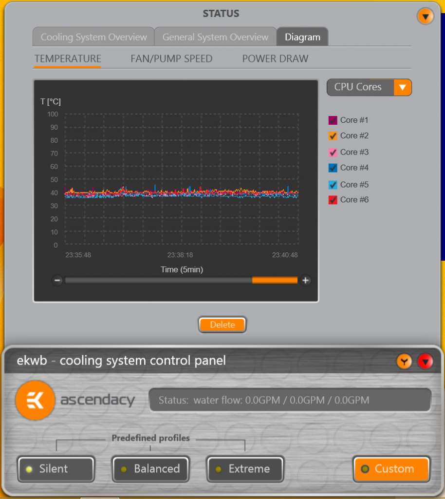
The charts are pretty basic. There is a drop down box on the right that lets you choose between the temp sensors plugged into the EK Ascendacy, or the temp readings from other hardware components in your system. You also have the ability to change the duration shown on the chart with a simple +/- box to click. The charts are drop dead simple....but you really can't do much with them.
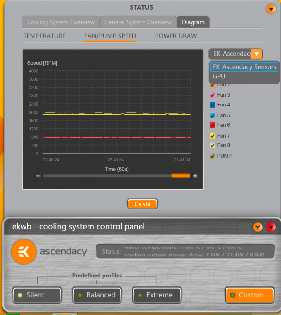
The second subtab is almost identical to the first, but shows rpm's instead of temps.
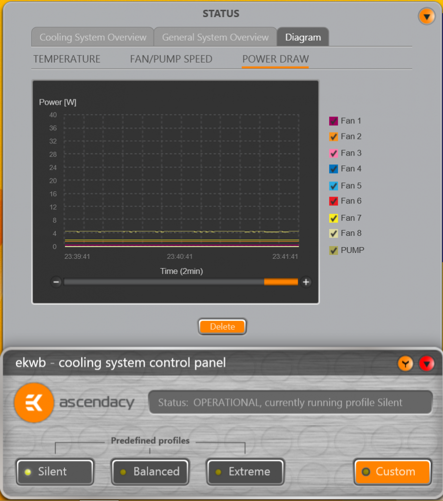
And the third subtab works very similar to the first two....but shows power draw in watts.
Again....even though you have ability to create a custom name for a fan in your profiles....these names do not carryforward into the charts or detailed status window. So you'll just have to remember that Fan 2 was the push fans on the 360 rad in the pedestal of your build. Lame.
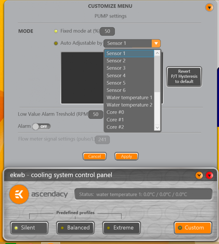
Almost done. Hang in there. The next screen is what you get when clicking the 'tool' option for a custom profile. It's your dashboard for making custom profiles. It shows you each of the 8 fan channels (2 voltage and 6 PWM) and one pump channel. I didnt' ever plug a second pump in, so I don't know for sure if you get an additional window on this screen....or if the one 'pump' window would control both of your pumps the same.
From the window above, you click which fan or pump you want to customize, and then it opens a screen like the one below....
You don't have a ton of choices for custom control....but it is drop dead simple. For each fan or pump, you can choose a fixed power value (i.e., 50%), or you can choose to have it controlled by a sensor reading. The sensor can be one of the EK temp probes, or one of the system hardware temp values. It was nice that the EK software had all these system hardware temps readily available. For the Aquasuite, you have to have a 3rd party tool, like Aida64, loaded and running to have access to these values.
Once you select a temperature source, you have a control curve with two points you can control. So although it doesn't offer near the precision or control that the Aqausuite controllers do, it is very simple to operate and setup. You may be losing a little bit of control here, but you can pretty much make it do what you want it to. Not near as comprehensive as Aqausuite controllers options, but much simpler to use.
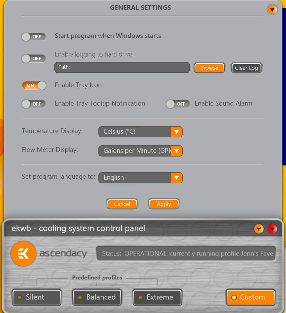
Last, but not least....this screen below is the general settings screen. Not much here to discuss...
Summary of Praises/Concerns
Overall....it's an exciting start for EK. Personally, I'm thrilled that there may be some decent competition for AquaComputer in this area. Always better for the consumer to have companies pushing each other to improve.
If you are comparing the Ascendacy to the Aquaero, the Ascendacy is clearly geared more toward PWM controlled fans. There are only 2 voltage controlled channels for fans, and 2 voltage controlled channels for pumps. You could use the pump channels to power a fan it you wanted, but since a lot of the status screens and charts are hard labeled to treat each connection as a fan or pump....you would render the status screens and charts meaningless if you did. Sure, there are also just 4 voltage controlled channels for the Aquaero....but I could use them for either pumps or fans.....or even lighting.....and then use the custom charts and labels to clearly identify what it was. No so with this version of the Ascendacy.
However, if you are using PWM fans instead of voltage controlled fans.....the Ascendacy would actually have a leg-up on the Aquaero, with it's 6 additional PWM channels.
I absolutely love the simple switching between profiles that the Ascendacy software allows. This needs to be copied by AqauComputer. Much slicker. I also like not having to use a 3rd party application to read hardware temps. Ascendacy does that out of the box.
As far as dashboard and charts and other custom reporting....the Aquasuite has a clear advantage over the simple approach of the Ascendacy. If you like to tinker and build your own dashboards....you want the Aquaero. If you don't care about this kind of stuff....the Ascendacy may be for you.
For me, I think the biggest Achilles's heel for this beta version of the Ascendacy software, is it's inability to control fans based on Water/Air delta temperature. The Ascendacy doesn't offer anything like the 'Virtual' sensors that Aquasuite allows. Virtual sensors allow you to use basic addition or subtraction of two different sensor values to create a new sensor value. So...a virtual sensor that subtracts your ambient air sensor from your water temp sensor....would provide a delta value for you that is what most people would use to control their fans/pumps. There is no such concept in the Ascendacy software right now. I believe this must be addressed.
My other primary concern is accessibility. The Ascendacy PCB will be mounted horizontal in a 5 1/4 bay slot. Because the waterblock is on the edge of the card, all of the voltage controlled ports are directly behind it. If you are using a single slot setup, then I think it will be downright impossible to plug in fans while the Ascendacy is installed. You would almost HAVE to have a free slot above the Ascendacy to have any room at all to make/change connections. Even then, it would be difficult to make a connection directly behind the waterblock while the Ascendacy is installed. You would be working blind.
Now....if EK is planning on the LCD screen taking up two 5 1/4 bays, then maybe it is worth it to have precious little room to make connections. But if the LCD screen will take up a single 5 1/4 bay, then I think most people will have to burn an additional bay above the Ascendacy just to have room to plug/unplug fans.
To be fair....we can't really judge the Ascendacy yet. The hardware and software are still subject to change before release. If they are able to price it where it is $50 cheaper than the Aquaero XT....then I think they may get a lot of takers. It doesn't do as much as the Aquaero.....but it is much simpler to understand and setup. That will be appealing to many.
Just got back the 2nd version of my 3d printed pump stand this evening! This print had some warping issues on the bottom. It's not too bad. I'll take some pictures of it as-is....and then I"ll see what I can do about maybe applying a little heat and trying to flatten the bottom some. Also, we learned that the 8 inch build height limit of the printer.....is actually closer to 7.8 inches. It totally garbled the letters I put on top of the pump stand because they ran outside of the build area. I can probably sand those off.
If I can't get this one to sit flat and look presentable....I'll tweak the design one more time and do a final print. Pictures tomorrow!
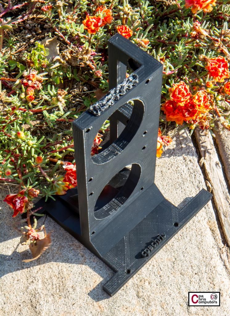
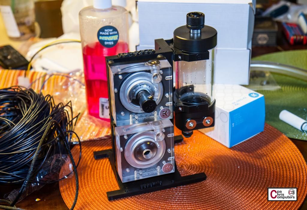
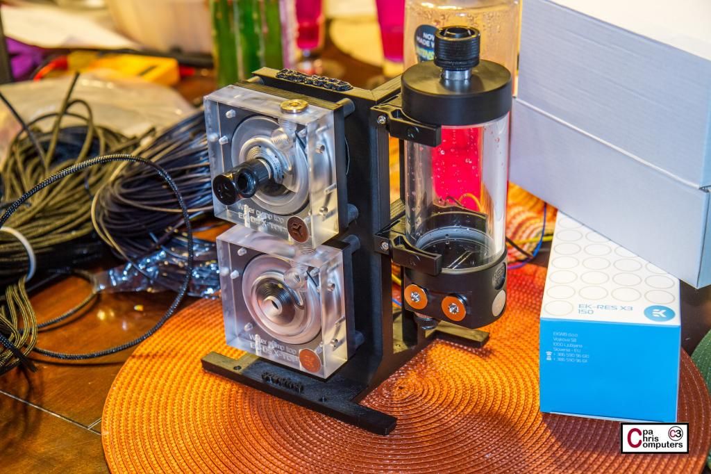
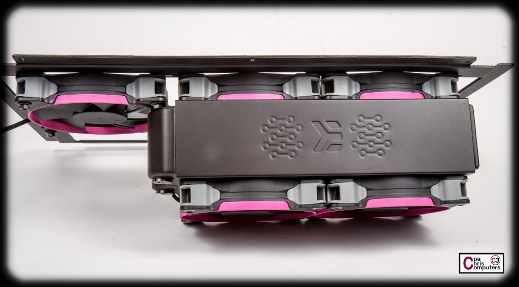
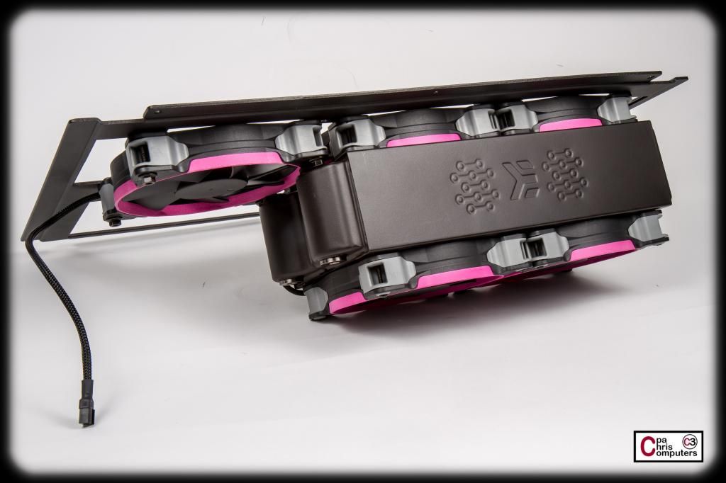
Pictures of v2 of the 3d printed pump stand.
Way too nice a day here today to take pictures inside....so outside we go. Overall....it came out pretty nice. You can see in this picture how the letters on top are garbled, since they were out of the top of the print space by just a little bit.
The lettering on the back and bottom came out very nice though.....
This one was printed with 100% fill rate, and it is a solid piece of equipment. Very sturdy. The vertical plate is much thicker than last time also. Very pleased with how sturdy it seems to be. Won't know for sure until I get some pumps mounted and running in it though.....
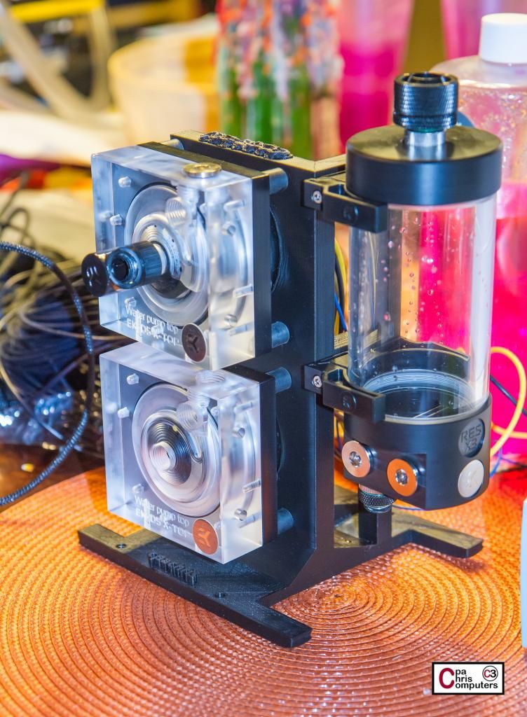
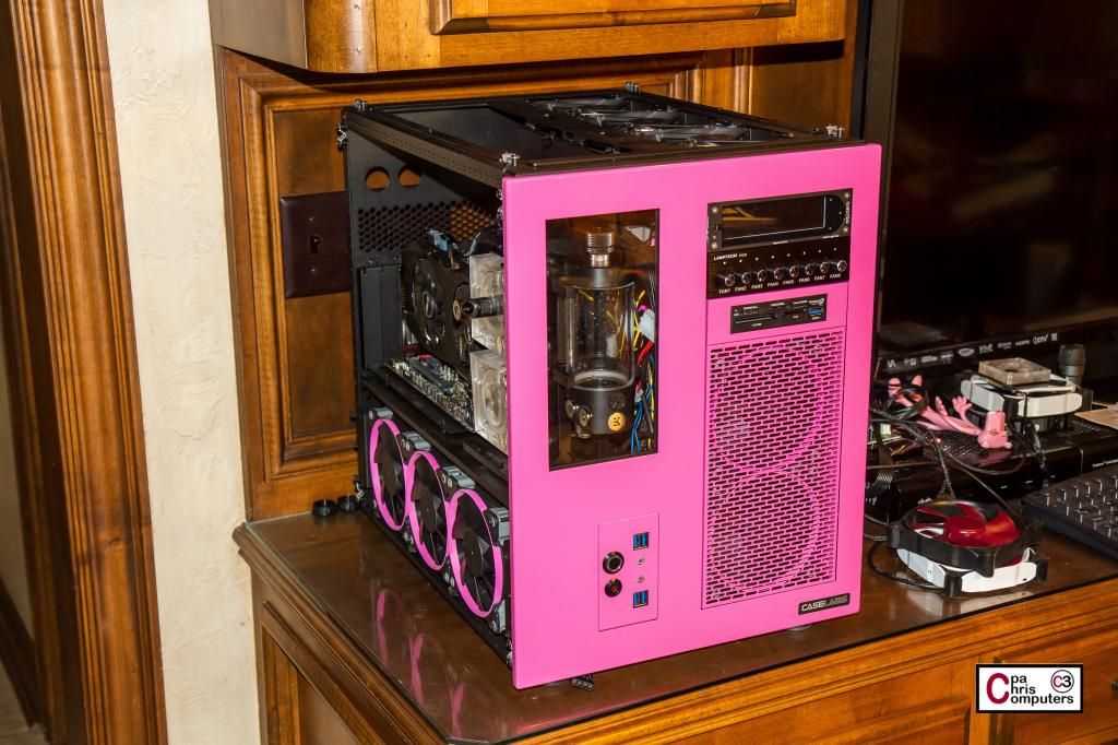
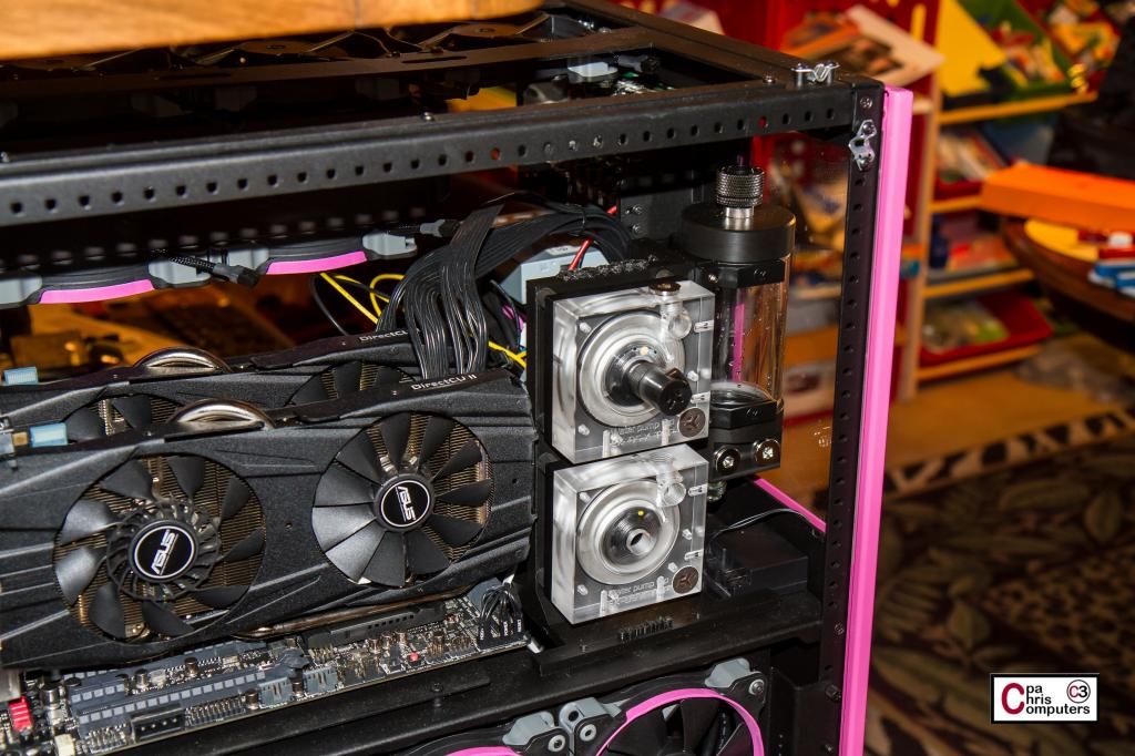
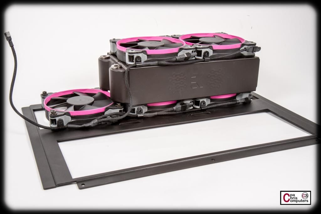
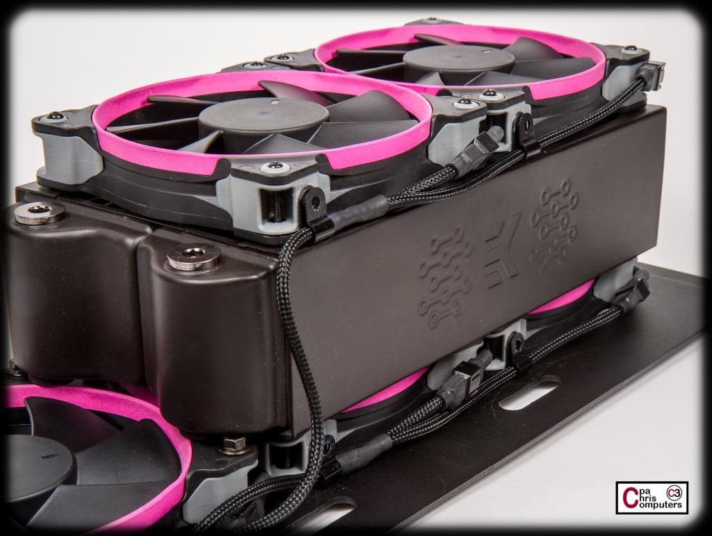
The pumps and reservoir mounted perfectly. Exactly as I had pictured it.
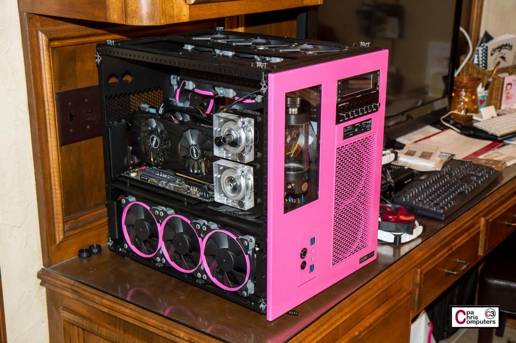
And the fit inside the case was pretty good also. A few nits....which I'll mention after the pictures....
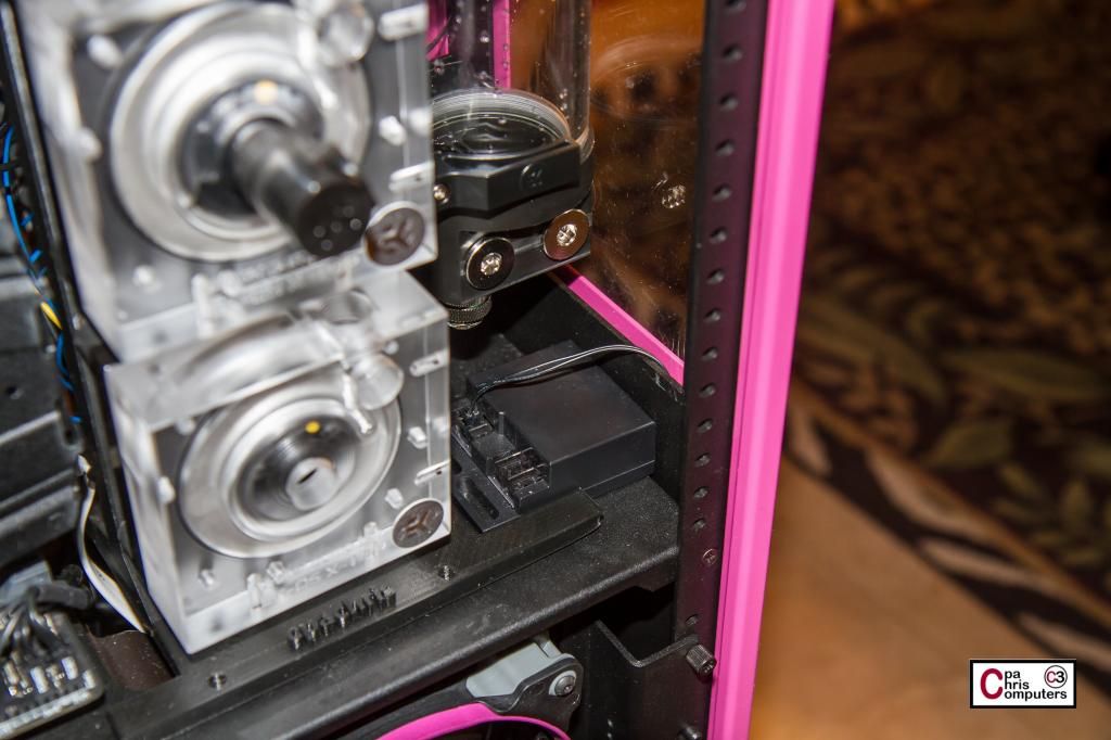
In the picture below, you can see how the legs on the front of the pump stand leave just enough space to put two of the modSmart cold cathode inverter boxes between the legs. They are fairly hidden because they are below the window level of the front of the case, and since they are black they blend right into the interior....
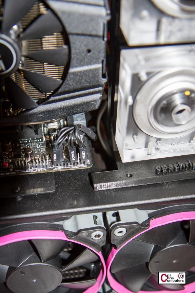
...and the legs on the back of the pump stand allow the existing cable management cutout on the S8 to still be utilized....
Overall.....I'm pleased.
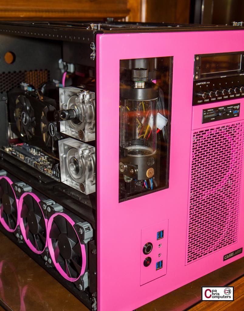
Now...for the nits. I didn't plan on how much space the fittings on the front of the pumps were going to take up. It makes me slide the whole pump stand further to the right of the case than I was planning on. Not a big deal...but it leaves the reservoir not perfectly centered in the front window. So...I either need to make a tighter bend with acrylic than this 90 degree fitting gives me...or I need to tweak the positioning for the holes for the reservoir mounts a little bit on a future version of the pump stand.
I still don't know for sure how much the slight warping will effect things. I was already planning on lining the bottom of it with some dense foam material. This alone may give it enough padding where the slight warping doesn't impact anything. We'll see...
More soon! Been spending some out of town time for family trips a lot lately...and haven't been around to work on the build as much as I had been. But it should kick back up into gear again now. Got one more trip planned in August....but that is it.

excuse my language but that pump mount is the, man that is some amazing work. Love the attention to detail, this is a great build
i9-10900k@5.3ghz//MSI MEG z490 Unify//32GB Gskill TridentZ b.die@DDR4666//RTX 2080ti(+150/+700) kingpin bios//Samsung 970 Pro//Corsair AX1200i
Custom Loop: Dual DDCs->Dual EK XE360 w/GT's -> HK IV CPU -> HK IV GPU ->EK X3 Res controlled by Aquaero 6
yep, you never fail to impress.
always simply amazing.
Aw shucks.Appreciate the kind words!
Made the EK page again!Still no link back to the build log.
https://www.facebook.com/EKWaterBloc...type=1&theater
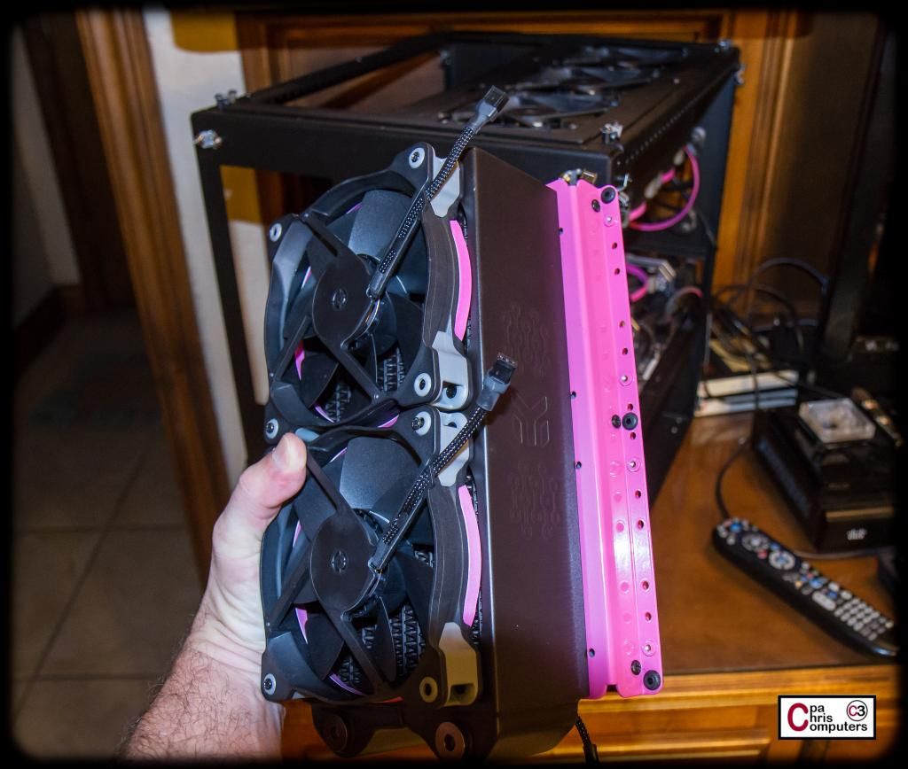
Picture update! Too much traveling lately...but we are almost done. One more trip next weekend and then we will settle back down into school schedule, and I should have some more time to finish this thing up!
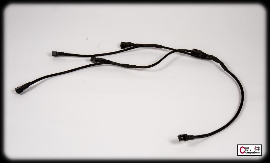
Last week, I was working on some more wiring. Decided to start with a fan power harness for one of the rads. After several starts/stops, changing of mind, etc., I finally settled in on the style of harness that I think will work the best for these rads. I think these take me the longest of all the wiring because of the soldering. I'm really just not that talented with a soldering iron. So it sometimes takes a few re-do's before I'm happy with the finished product. Here is what I ended up with.....
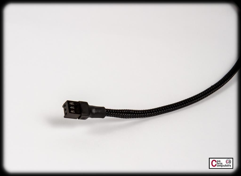
A strange looking cable, indeed. On the bottom of the picture above, you'll see a typical female fan connector....which then branches into 5 separate male fan connectors. Close up of the female end below. This will plug into the Aquaero for control of all 5 fans on one channel....
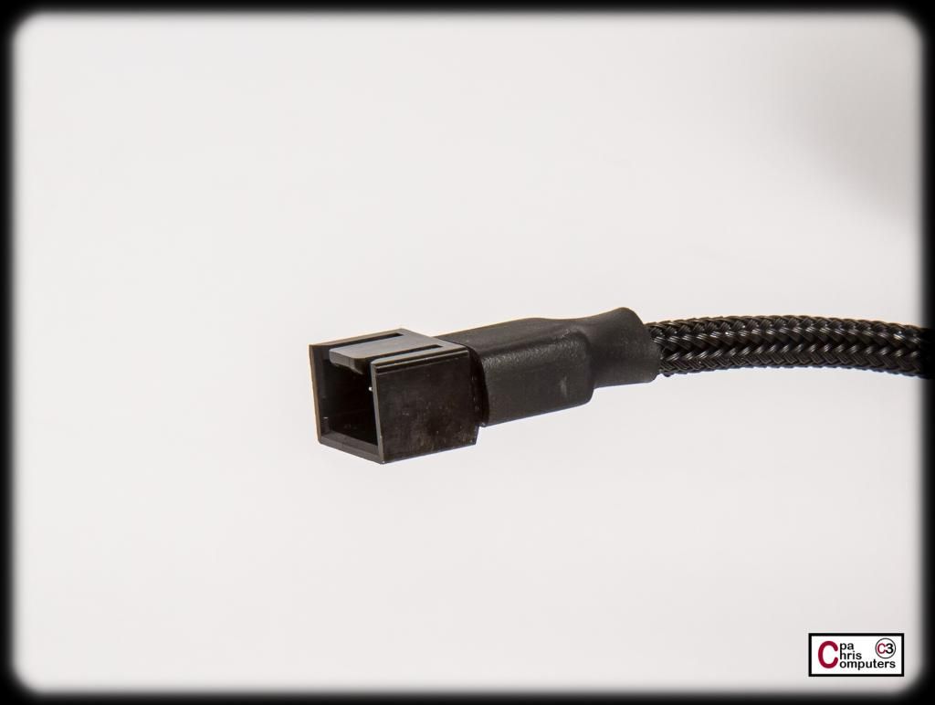
And below is a closeup of one of the male ends. These connectors and pins I got from Lutro0, and they were of excellent quality. Much nicer than the pins/connectors I got from FrozenCPU for my last build. These pins go in nicely with a satisfying click. The hooded portion of the connector keeps the pins from making contact with the case at any time, and helps prevents shorts.
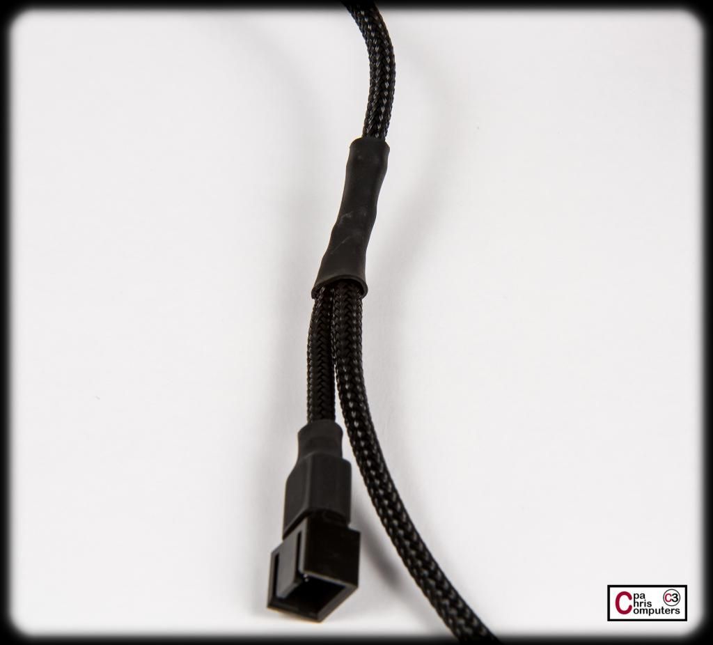
And below is a close-up of one the branches of the wiring where I had to solder. Some of the Lutro0 heatshink covers any indiscretions nicely....
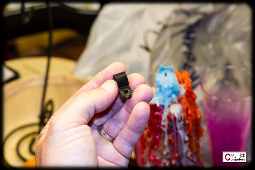
Since this cable was going up next to the radiator, I really didn't have a way to screw in these cable clips that I had sitting around...
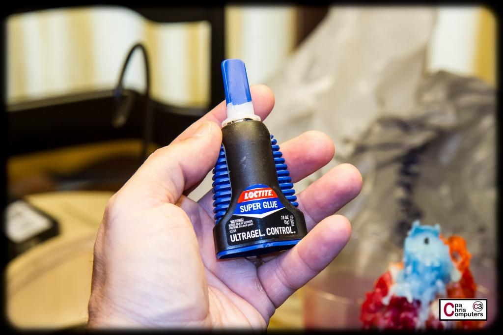
My sweetie Jen suggested I just use a touch of superglue and put the clips directly on the fans....
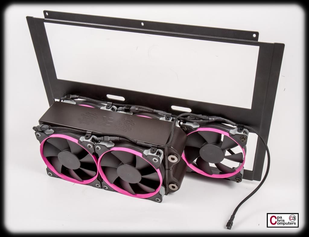
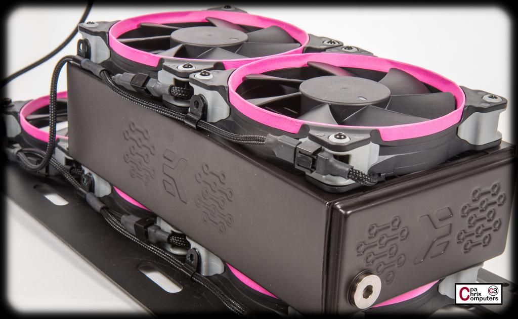
I'm very happy with the end result. The cable clips keep the wiring close to the black part of the fan frame, and the wires don't hide any of the pink accent rings. The cable clips are securely on the fan, and still allow the cable to slide back and forth inside the ring, so if I ever need to remove the cable or a fan for any reason, it shouldn't be an issue.
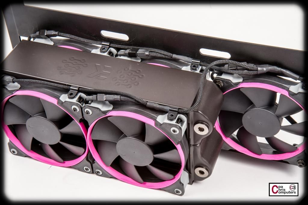
The pictures above are from the side of the radiator that will be in the middle of the case...not up against a window. The black cables almost disappear into the black fan frame and black case.
Below are a couple of pictures from the side of the radiator that will be against the window. You can't see any cables at all on this side. Very clean look.....
...and, a few more parting beauty shots. I love the look of these Corsair fans on the thick EK XTX radiators.
I'm working on the wiring for powering up the Aquaero and the Lamptron now. More soon!
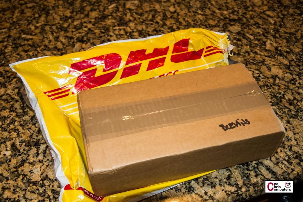
Question: What do you post online when a package from Slovenia arrives with a NDA and a promise to be shot if you reveal any details?
Answer: Nothing. For now.
But stay tuned.......
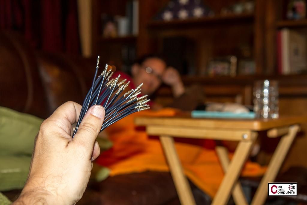
Some progress on the GPU cables.....
You know my love for assembly line production. The following steps were done over a two night period while catching up on all of our DVR'd Big Brother episodes in the living room with my sweetie.
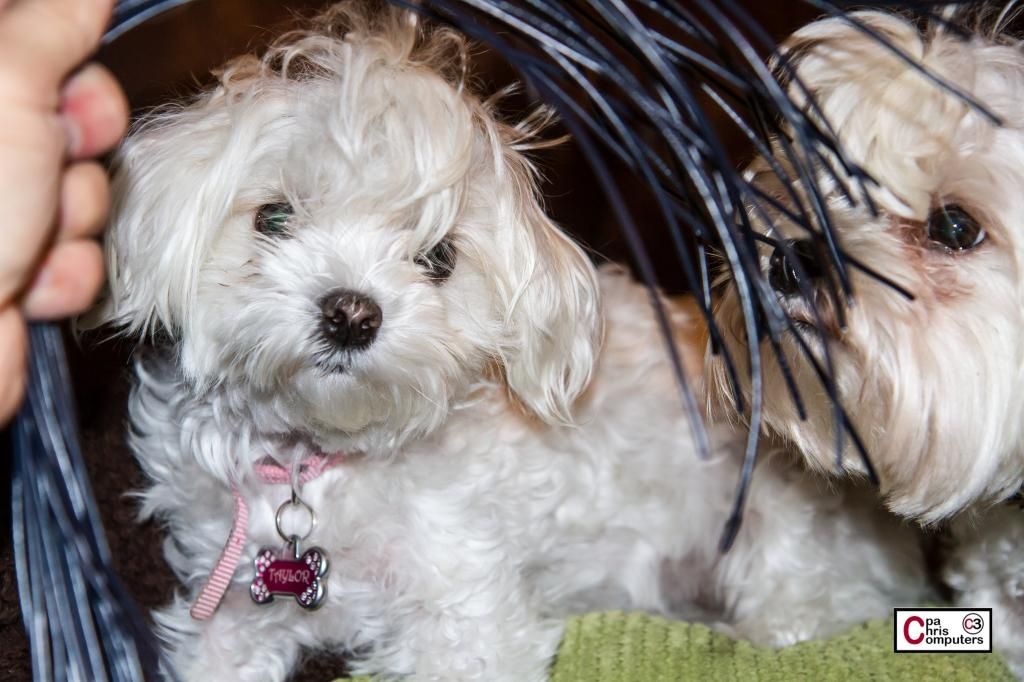
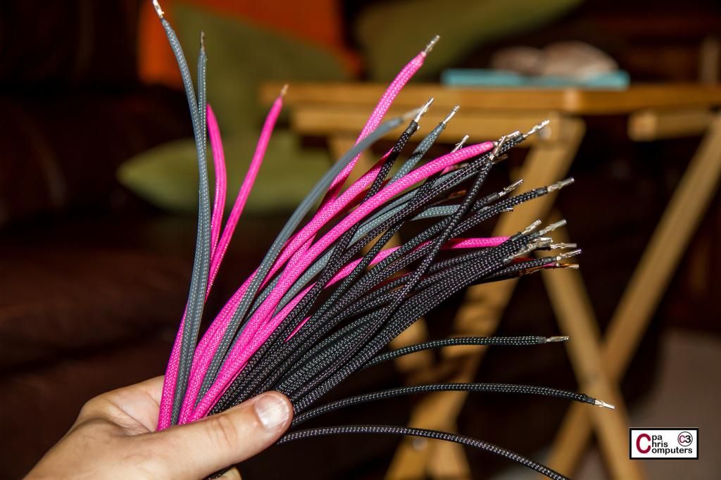
Step One -- Cut 32 pieces of wire, long enough to cover any of the routing ideas that are lingering around in your head. Proceed to torture the dogs with the wires for at least 15 minutes....
Step Two -- Use your awesome Lutro0 wire strippers and take off the insulation on one end of all 32 wires. Proceed with calling Jen's name over and over while she's watching TV....and then showing her the wires. Try to remember than Jen won't appreciate it if you leave all the little wire bits on the living room carpet.
Step Three -- Use your awesome Luto0 crimper to put a female ATX pin on one end of all 32 wires. Proceed to repeat Jen's name until she finally gives up and stares at you.
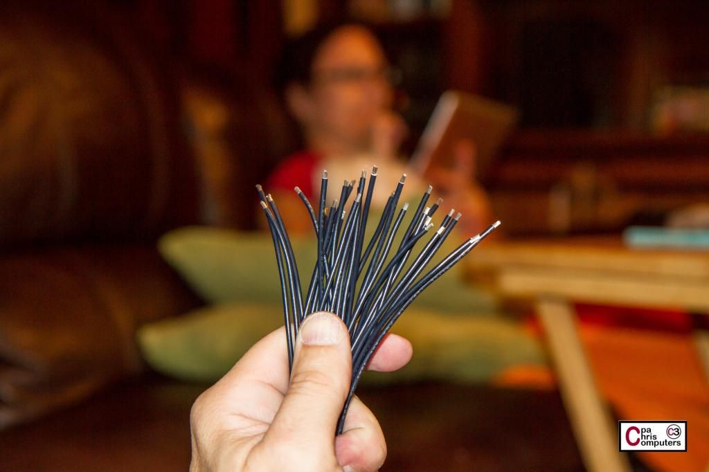
Step 4 -- Cut sleeve long enough to cover wire, and then go ahead and melt one end onto the ATX pin you did in the previous step. Proceed to announce loudly and repeatedly...."Look at my colored spaghetti!!!"
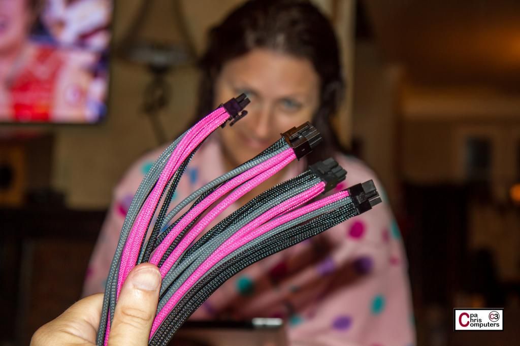
Step 5 -- Insert the end of the wire with the pin into a connector. Proceed to insist that Jen come back into the living room to serve as a background image for my wire shot.
What I'll do next is plug the connector end into the GPU's and do some test routing of the cables using different options....and decide which one I like best. Then I'll cut the cable down to size, and start putting pins on the other end of the cable also. The part that takes the longest is melting the sleeve on the pins. You do anything 32 times and it just takes awhile to do. For each of the 32 wires,
-- I'm cutting the sleeve to the right length,
-- stretching it tight,
-- adjusting the cut if necessary,
-- putting on heatshrink,
-- melting it till it's gooey,
-- risking the flesh on my fingers to press it down onto the pin while it's hot,
-- and then cutting off the heatshrink.
When you combine doing each of these steps 32 times....while trying to watch a TV show....it takes awhile. But I'll keep you posted on progress.
Alas, no progress this weekend because we are leaving on a little family trip tonight and will be gone through Monday.

Nice colors and good job !
______________________________
Banchetto 101 | Corsair TX850W V2 | ASUS P5W DH Deluxe | E8600 @ Noctua NH-U12F | 4GB OCZ DDR2 800 OPS Edition | EVGA GTX280 | HP w2408h | SB X-Fi Xtreme Gamer Fatal1ty | Genius Home Theater 5.1 | PLextor PX-820SA | LiTe-ON LH-20A1S | OCZ RevoDrive 120GB | WD 500GB AAKS | WD 2TB GP 64MB EARX | UPS APC Back-Up RS 1500VA LCD | W7 x64 & sOnY VaIO i3 2.2GHz # 8GB
Thank you sir!
how long were the wires on this? im having my guy make one tomorow for me
About 1.5 inches. You may need to make some of the wires longer than others if they do more of a crossover than rest of wires.
I did something similar for the GPU cables, but haven't taken any pictures yet.
Hey bro quick question, When doing custom sleeving making ur own cables,You insert the cables into the PCIE connector any way you want also same goes with the 24 pin ? Or do you follow the same routing as the default cables that come with the PSU? I wanna start my own custom sleeving just not sure if i purchase all the tools,sleeving etc I might make a mess and actually ruin my PSU lol and connectors..
Another thing I find funny is AMD/Intel would snipe any of our Moms on a grocery run if it meant good quarterly results, and you are forever whining about what feser did?
 Posting Permissions


 Reply With Quote
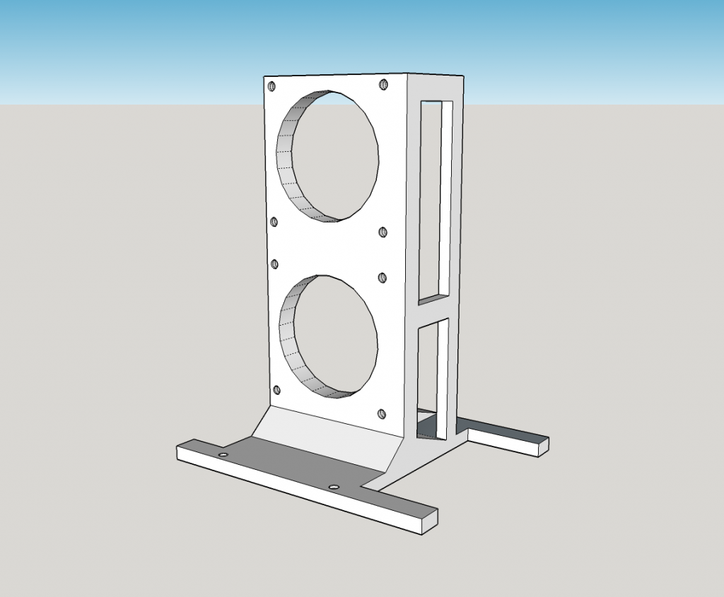


Bookmarks