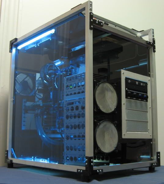
Page 1 of 2 12 LastLast
Results 1 to 25 of 27

Thread: Exoframe 2.0

  1. #1
    Xtreme Enthusiast
    Join Date
    Dec 2004
    Location
    Chico, CA
    Posts
    749

    Exoframe 2.0

    Exoframe 2.0


    A few years back I built my Exoframe Project.


    Build log is here.


    Completed project thread is here.


    I was recently contacted by GMdoubleG at the ocforums about possibly building a similar case. I told him that I could, but it would take a while because, as I mentioned in the original thread, I’ve always wanted to build stronger 3 way corner brackets from steel.

    Well, I contacted some local NorCal guys, Erik at Norcal laser and Matt at Mione’s Solidworks, and after a few revisions, I had a steel 3 way corner bracket.


    The thread on the design and fabrication of my 3 way corner brackets is here.


    GMdoubleG had some specifics.


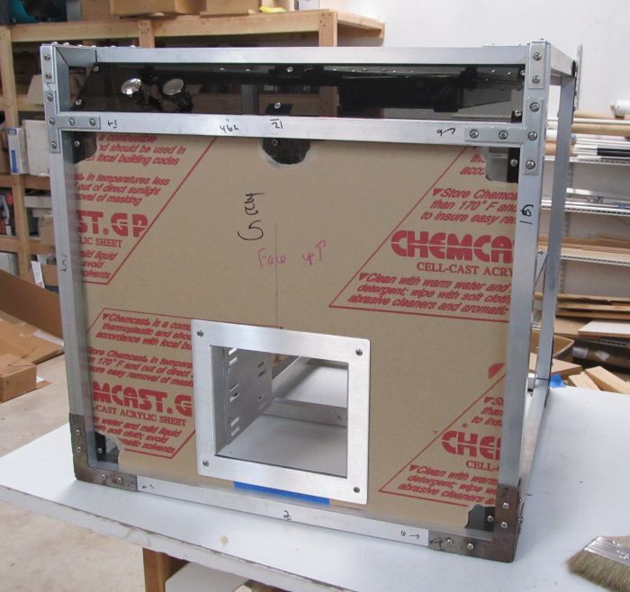
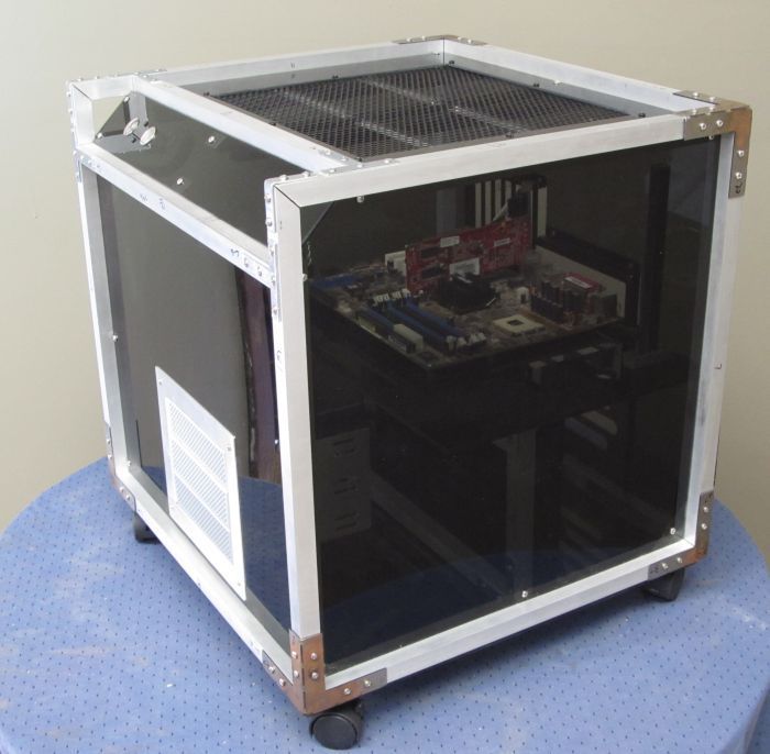
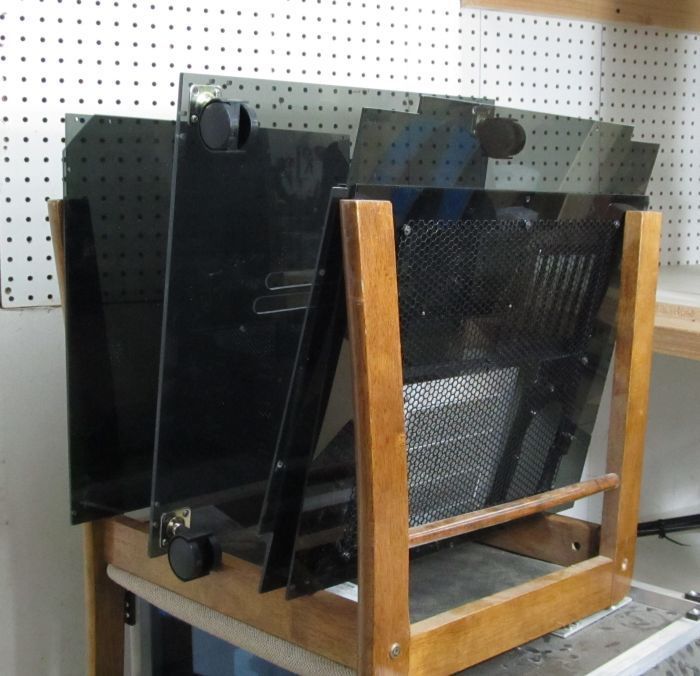
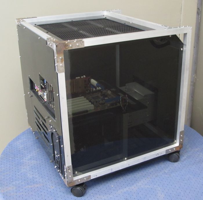
    Looking for more of a cube shape. Horizontal motherboard. Two 2x120mm radiators up top.

    Plan was to leave the aluminum bars and steel corner bracket unfinished--he would have a local painter powdercoat and/or anodize.

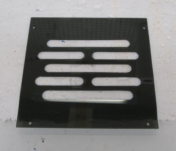
    Going with all gray plastic paneling.


    He passed along some general design drawings:


  2. #2

  3. #3
    Xtreme Enthusiast
    Join Date
    Dec 2004
    Location
    Chico, CA
    Posts
    749
    Now if it appears like this thread is very similar to my Exoframe original thread, the answer is I intentionally went down (and even consulted the old thread) the same design process because then I could remember what worked and didn’t work and improve.


    So, I first started 3 dimensionally laying things out, going back to some old leftover extruded aluminum bar parts (remember the old Lubic stuff).


  4. #4
    Xtreme Enthusiast
    Join Date
    Dec 2004
    Location
    Chico, CA
    Posts
    749
    Once the dimensions of the overall frame were set, it was as easy as generating a cut list:


    I cut the pieces with an inexpensive horizontal band saw:


    I decided to go with the 3 way corners meeting at double miters:


    Its stronger and looks cooler:


    Started getting the frame together:


    And finally done:


    Sturdy and light:


    (click to play)

  5. #5
    Xtreme Enthusiast
    Join Date
    Dec 2004
    Location
    Chico, CA
    Posts
    749
    The next step was to create a subframe to support the horizontal motherboard tray.


    I began putting together the motherboard tray and the back panel together:


    The motherboard tray was cut from ¼” thick opaque black plastic.

    The back panel (and the rest of the outside panels) was cut from ⅛” transparent gray plastic.


    Next, I cut out the space and mounted the pci rack:


    This is a nice pre-fabricated rack built by dangerden.


    Have to make sure everything fits nice:


    Then I went to work on the motherboard tray:


    I made pass thru channels by first drilling ⅞” holes at the ends with a unibit. Then connecting the holes with my scrollsaw.


    And there you go:


    Plan was to have the resevoir in a position like so, with the pump down on the lower level:


  6. #6
    Xtreme Enthusiast
    Join Date
    Dec 2004
    Location
    Chico, CA
    Posts
    749
    Next, I fabricated the panel hanger brackets:


    What do these brackets do?

    If you stop and think about it, if you have a tubular frame structure and you want to cover the sides, but the panels are to be INSET into the frame, what do you mount the plastic panel to?

    You need to add some inset brackets. I’ve highlighted them in purple in my previous exoframe project:


    But if you stop and think about it, if the panels are all inset, then how do you mount these panel hanger brackets?


    And that is where I get tricky:

    The back and bottom panels of the case, which are not very noticeable, are in fact surface mounted--this leaves part of the frame accessible for mounting points on this end of the hangers.

    The other end of the hangers then mount to the cross bars inserted to create the sloped front top face.


    Red and Yellow arrows show where the panel hangers mount to the frame.
    Blue arrow shows how the top panel will sit on top of the hanger mount.
    Green arrow shows how the side panel will sit and mount to the hanger mount.


    I’m going to skip a little forward for this pic, but it shows nicely how the panel hangers work if you look closely:


  7. #7

  8. #8
    Registered User
    Join Date
    Oct 2009
    Location
    Perth, Western Australia
    Posts
    83
    This is looking awesome. It's amazing how simple this build is when you've broken it down like this and yet how great it looks as a finished product. Looking forward to more updates!

  9. #9
    Xtreme Enthusiast
    Join Date
    Dec 2004
    Location
    Chico, CA
    Posts
    749
    Built a tray for the power supply:


    Mounts like so:


    Then I cut an access panel for the hard drive rack:


    GMdoubleG wanted passive air exit to create airflow over the drive cage, so we came up with this sort of design:


    I started by created all the ends of the cut slots with a ⅞” unibit:


    Then connected the dots with my scrollsaw:


    Mounted up:


    And the view from the inside:


  10. #10
    Xtreme Enthusiast
    Join Date
    Dec 2004
    Location
    Chico, CA
    Posts
    749
    I decided to cut the front bevel panel.


    The piece has a beveled cut on each side so that it’ll sit down on the frame.

    I’m going to say that I’m in no way sponsored by them, but I think one of the best tools I have ever purchased, and I think the best tool out there for doing any sort of panel cutting (short of an industrial laser):

    Festool plunge cutter

    http://www.rockler.com/product.cfm?p...6&site=ROCKLER


    I have a nice big table, and on top of that a sacrificial surface of 1.5” rigid insulation.


    It’s as simple as drawing a line on the panel you want to cut, laying the track on the line, and then cutting.


    Even on bevel cuts on plastic, I have never chipped an edge. If you actually read the instruction manual, and properly adjust the depth and speed, and I get a roughly 100 grit sanded edge with a little machining line, straight off the saw.

    It is a bit expensive, but to come even close, you need a $250 table saw and a $150 saw blade, you will still chip on exit cuts, you’ll still occasionally get inaccurate cuts, and you might chop off a finger tip.

    Anyway, advertisement = done.


    Then I added some standard chrome push buttons:


    Next, I tackled the wiring harness.


    Since the frame is square tube and completely disassemble-able, I will run the wiring harness thru the frame.


    The wiring harness consists of 4 pairs--power switch, reset switch, power LED, HDD activity LED.

    Drill a few holes in the frame, then partially disassemble it, and I can feed the harness thru the frame itself:


    Here I’ve actually highlighted the entire route:


    And here is the end product: super clean!


    I didn’t much in the way of fancy cable meshing, as gmdoubleg plans to do that himself.

  11. #11
    Xtreme Enthusiast
    Join Date
    Jan 2008
    Location
    Athens -> Hellas
    Posts
    944
    Awesome! Just subscribed to watch the rest....

  12. #12
    Xtreme Enthusiast
    Join Date
    Dec 2004
    Location
    Chico, CA
    Posts
    749
    Sorry all, I've been on vacation in Alaska with only intermittent internet--updates by the end of the week.

  13. #13
    Xtreme Enthusiast
    Join Date
    Dec 2004
    Location
    Chico, CA
    Posts
    749


    Woohoo! Add me to the Denali 30% club, probably 1% club!


    Next step was to fabricate the front panel.

    Simple rectangle, with a cutout for the 5.25 bay mounting hardware:


    And the last real fabrication step was the top or lid panel.

    gmdoubleg planned on having his dual 2x120 radiators up top here.


    So I mounted 4 rails with some spare extruded T bar I had:


    With crossbars, it would give flexibility in mounting the radiators in terms of placement for the loop and/or even swapping in triple 120mm radiators:


    With this in mind, I cut the plastic panel:


    And then mounted black hex mesh to allow for air movement across the radiators:


  14. #14
    Xtreme Enthusiast
    Join Date
    Dec 2004
    Location
    Chico, CA
    Posts
    749
    Final Pics (sort of).


    I’m going to have to leave the final final pics to gmdoubleg after he does his finish work (anodizing? powdercoating?).


    Focusing in on the back side, there is a hard drive access panel:


    2 minutes with a screwdriver, and both side panels and top panel can be take right off, allowing a lot of access to the inside components:


    5 minutes with a screw driver and all 6 major panels come off just like that:


    And your system is nekkid:


    (Once again, admire the cable harness running thru the framework itself!)


    And my usual demonstration of the strength but lightweightness of the nekkid station:


    (Click to play)


    And a couple of more pictures:


    The pictures don’t quite do it justice. The dimensional aspect of having the plastic panels inset within the frame really catches the eye.


    Its been a pleasure and an honor to work with gmdoubleg. I would build another in a heartbeat.

  15. #15
    Xtreme Addict
    Join Date
    Dec 2007
    Location
    Earth
    Posts
    1,787
    Looks great. you gonna put a coat of paint on the frame?
    Sandy Bridge 2500k @ 4.5ghz 1.28v | MSI p67a-gd65 B3 Mobo | Samsung ddr3 8gb |
    Swiftech apogee drive II | Coolgate 120| GTX660ti w/heat killer gpu x| Seasonic x650 PSU

    QX9650 @ 4ghz | P5K-E/WIFI-AP Mobo | Hyperx ddr2 1066 4gb | EVGA GTX560ti 448 core FTW @ 900mhz | OCZ 700w Modular PSU |
    DD MC-TDX CPU block | DD Maze5 GPU block | Black Ice Xtreme II 240 Rad | Laing D5 Pump

  16. #16
    Xtreme Enthusiast
    Join Date
    Dec 2004
    Location
    Chico, CA
    Posts
    749
    Thanks,

    This project is not for me, but for a member at the ocforums. He has his own plans on (I believe) anodizing the frame and powdercoating the bracketry.

    You may notice every unique bar and bracket has numbers and orientation scribbled on them because I know the first thing he is going to do when he receives it is disassemble it.

    So, there should be more final final pics when he finishes the finishes.

  17. #17
    Xtreme Enthusiast
    Join Date
    Dec 2004
    Location
    Chico, CA
    Posts
    749
    This project has been off the radar for a while, after I shipped it to Gmdoubleg.

    In the interim, he actually completed and finished the case (anodize and powdercoat) but found it didn?t fit his lifestyle.

    So the opportunity came up for me to re-acquire the Exoframe 2.0, so I did!

    Incidentally, once this is finished, it?ll go back on sale in the ocforums classifieds, but please keep all discussions about that in that thread.


    Gmdoubleg completely disassembled the case (which is probably the only safe way to ship) and packaged everything excellently:


  18. #18
    Xtreme Enthusiast
    Join Date
    Dec 2004
    Location
    Chico, CA
    Posts
    749
    Start with the base bars:


    Added the bottom panel with caster wheels.


    Wrangled the wiring, which runs thru the inside of several of the frame tubes:


    Power supply shelf:


    Almost complete:


    And got the frame assembled:


  19. #19
    Xtreme Enthusiast
    Join Date
    Dec 2004
    Location
    Chico, CA
    Posts
    749
    It was time to mount all the panels.


    Top panel:


    Front panel:


    The back panel is one of my finest examples of crafting plastic:


    Mounted:


    Switch panel:


    Took a moment to make sure my universal radiator mount was all dialed in:


    Got a Swiftech MCR220 and a MCR320 fitted no problems


    With the top back on:


    And here you go: a quick series of completed pics:


    Next: my series of higher resolution clean and nice completed pics….

  20. #20
    Xtreme Enthusiast
    Join Date
    Dec 2004
    Location
    Chico, CA
    Posts
    749
    Exoframe 2.0 Completed!


    Just to recap. This was an exoframe project I built for another thread member, but that I purchased back, and will go back for sale for anyone interested.

    Exoframe refers to the overall design construction. The case primarily consists of a ?” aluminum square tube frame. The frame is completely stand-alone. All of the paneling is non-structural.


    Here is a picture of the frame as I completed it:


    Since none of the enclosing panels are structural you can remove them all quickly and have maximal access to your components. In fact you can just operate the system open bench style.


    Or add the panels back and you have a completely enclosed case:


    The framing elements remain visible, even with the panels on, hence the name.

    We opted for a simple black and white scheme. The frame has been anodized in black, and the bracketry powdercoated white.

    It is a box design, with a slanted panel for the switch cluster. It is also mounted on caster wheels to move about.

    The front has a bracket for mounting 3x 5.25 bay slots.


    .

  21. #21
    Xtreme Enthusiast
    Join Date
    Dec 2004
    Location
    Chico, CA
    Posts
    749
    The switch cluster has a domed chrome pushbutton for power, flat chrome button for reset, and blue and red LEDs for power and HDD activity.


    The top panel has a grilled section.


    This allows air intake or exhaust for side by side radiators, as needed:


    The mounting brackets are fairly universal and can fit side by side Swiftech MCR 320s as in the picture.


    .

  22. #22
    Xtreme Enthusiast
    Join Date
    Dec 2004
    Location
    Chico, CA
    Posts
    749


    The paneling is all ⅛” transparent gray acrylic. I think it looks pretty understated, but with some internal lighting, you can see the internals well.


    The back panel has your i/o’s, power supply bracket, and an access panel for your hard drives.


    The hard drive access panels has some slots to keep some airflow thru the hard drives.


    It can be easily opened with thumbscrews, allowing access to 4 full sized hard drives.


  23. #23

  24. #24
    Xtreme Enthusiast
    Join Date
    Dec 2004
    Location
    Chico, CA
    Posts
    749
    As I have mentioned, the panels can all come off with a few screws. Then you get very unrestricted access to your components:


    Another feature I’ve built in is something featured (or actually hidden) in this pic:


    If you take a close look, I actually run the cables for the switch panel within in the frame itself. One less set of cables cluttering up the insides.


    This case was designed with some general layouts in mind for watercooling.


    The radiator/s have their location up top.
    The idea was for a round tube radiator type--a bracket was fabricated, and pass-thru holes are there--plus the pump on the lower deck.

  25. #25
    Xtreme Enthusiast
    Join Date
    Dec 2004
    Location
    Chico, CA
    Posts
    749
    And there you have it! Exoframe 2.0:


    Thanks for the support of the forums I?m posting at.
    Thanks to gmdoubleg for commissioning the design.
    Thanks to my wife!

    My usual sources: mcmaster.com, onlinemetals.com, jab-tech, performance-pcs, frozencpu, Norcal Laser, mionesolidworks, delviesplastics.


    Also, I direct you to my other ongoing and very related project, the exoframe mini.

    Link → here

Page 1 of 2 12 LastLast

Bookmarks

Bookmarks

Posting Permissions

  • You may not post new threads
  • You may not post replies
  • You may not post attachments
  • You may not edit your posts
  •