


Hello Everyone!
Last time we left off... I made a few "minor" mistakes in trying to achieve my mirror finish on my exterior pieces, cutting all the way through my base coat in one or two places. Whoops.
Anyway, I went on to repair the pieces by sanding down a few layers of the clear coat, and in the mistake areas all the way back to the primer.
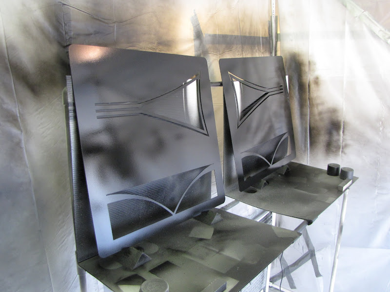
After that, I laid down a new base coat, followed by a heavy re-coat of clear. Hopefully this will give me a bit more of a buffer of clear that I can cut through to get rid of all the orange peel. Now, I just had to wait a week for the clear to dry again.
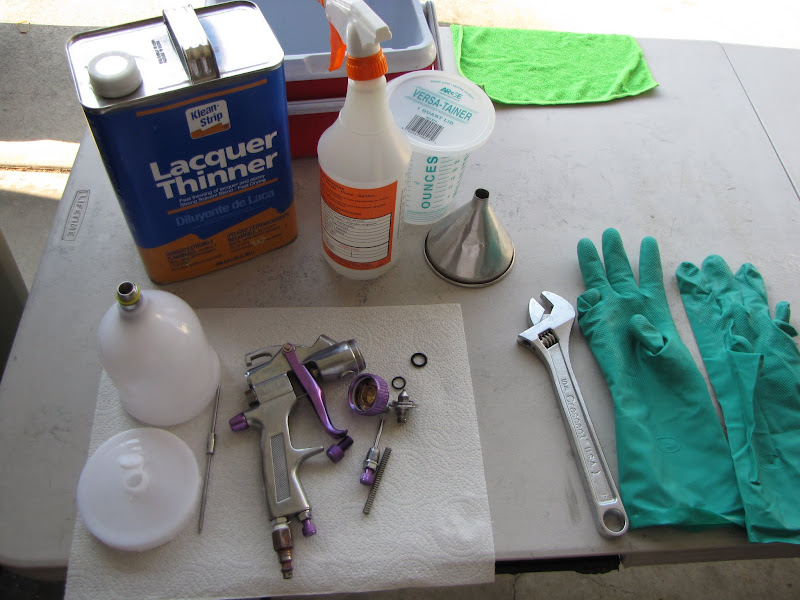
... and of course, I cleaned out my spray gun again. I picked up some different cleaner (lacquer thinner instead of mineral spirits, works much better...) and a few extra tools like a solvent-proof spray bottle to help with cleaning.
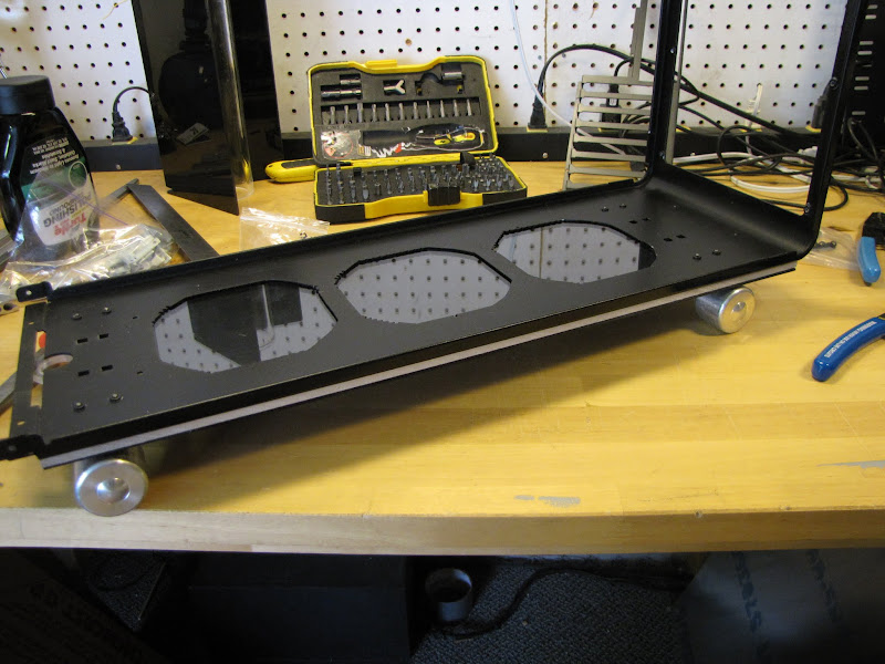
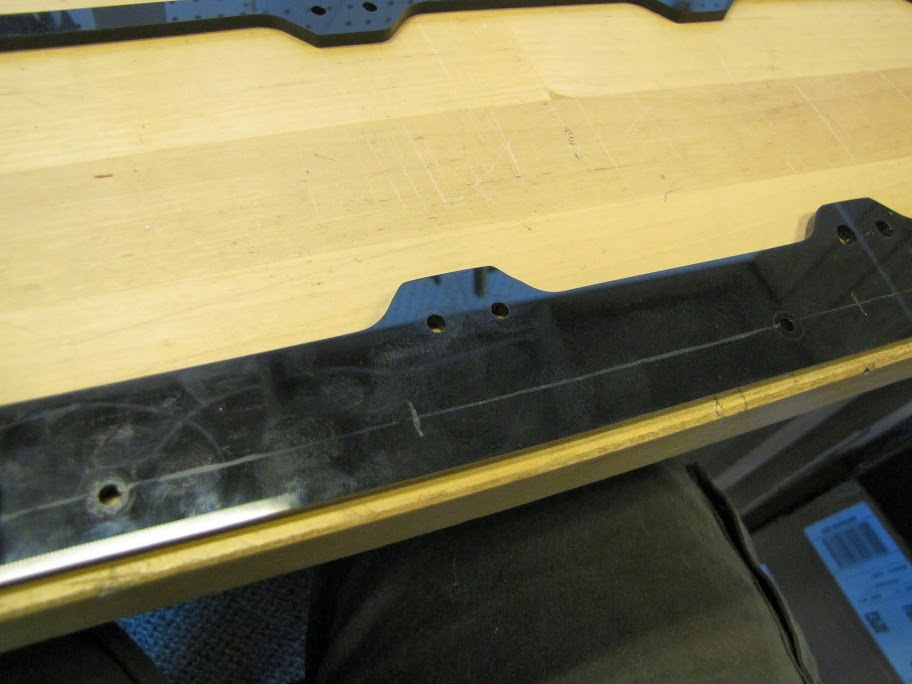
One week later (this weekend!) I finally got to make another shot at wet-sanding the exterior pieces. I started off with the bottom plate of my case... which will actually not be visible... but I figured it's a good piece to test on.
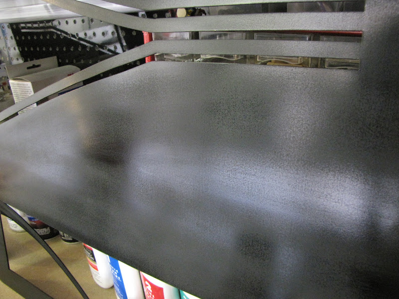
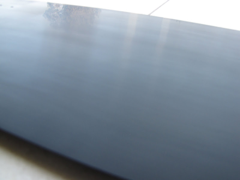
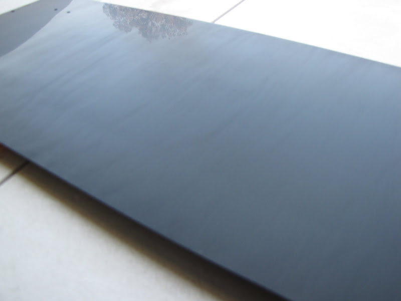
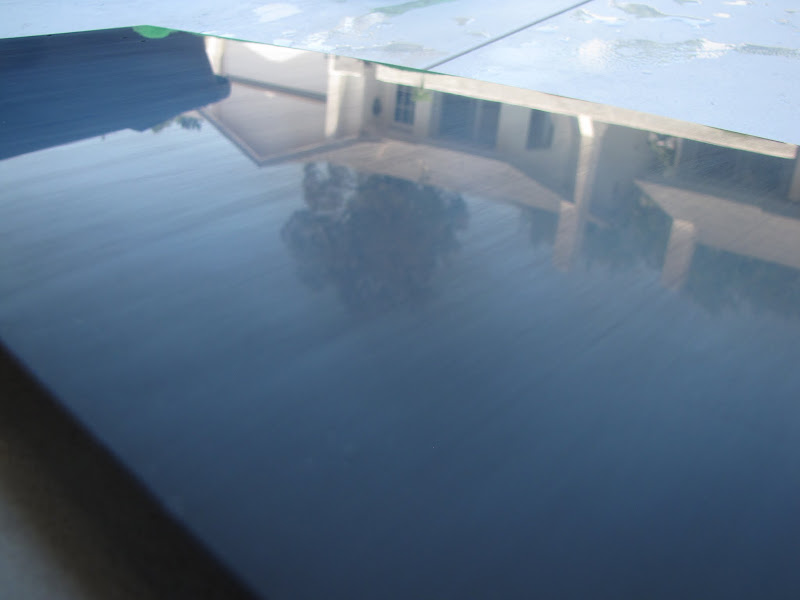
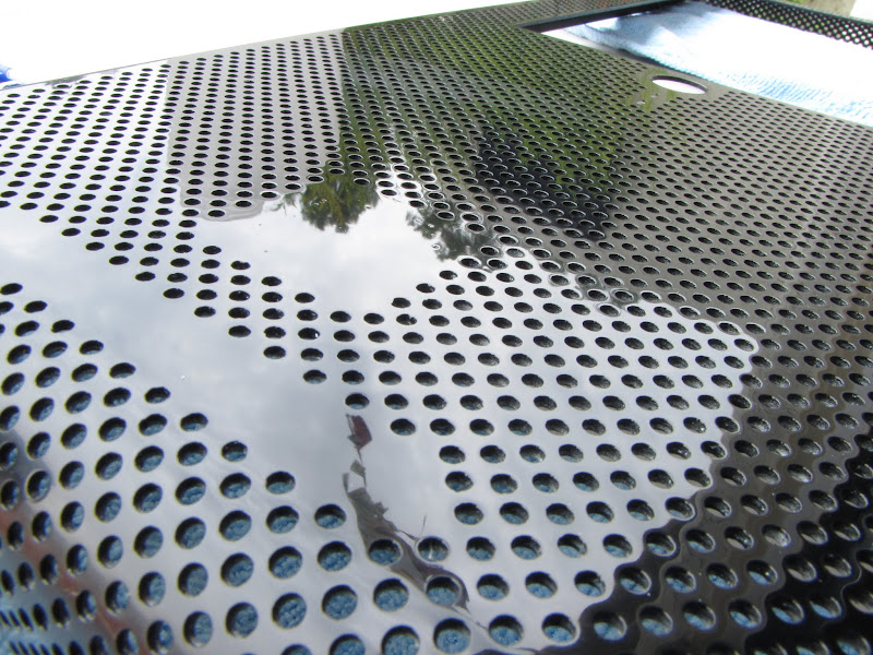
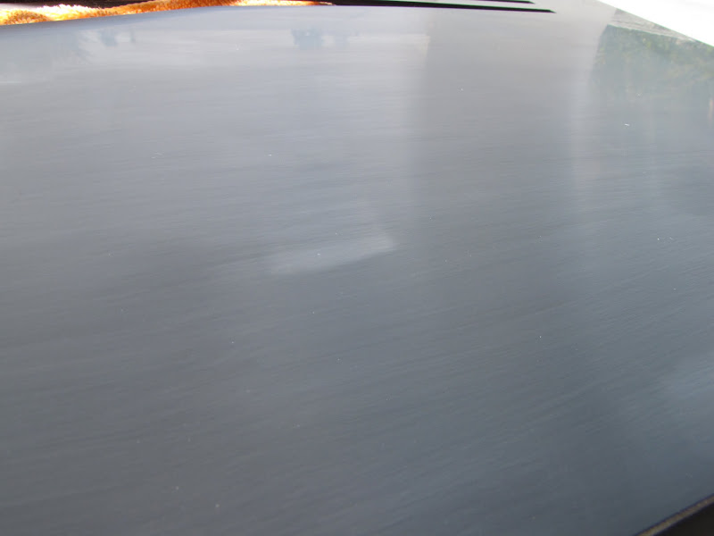
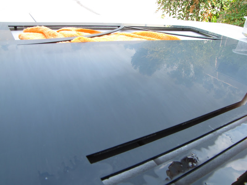
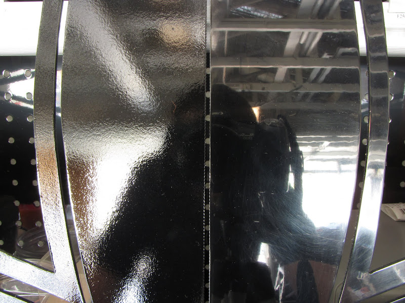
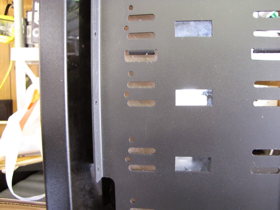
First, I filled a painting tray (one of those plastic things you use with a paint roller to paint a house) with water and a dab of soap, and put all of my sandpaper in to soak for a few minutes. Once soaked, I started with 1000 grit as I had a lot of orange peel to cut through. This part took the longest, I had to be very careful not to cut through edges, but had to smooth out every single little dot. After about an hour of working on the piece with 1000 grit, I ended up with a finish like this:
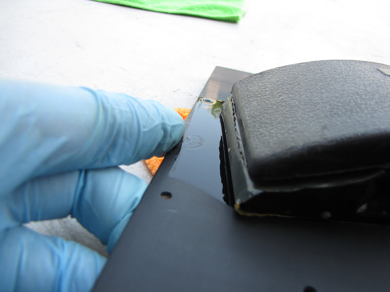
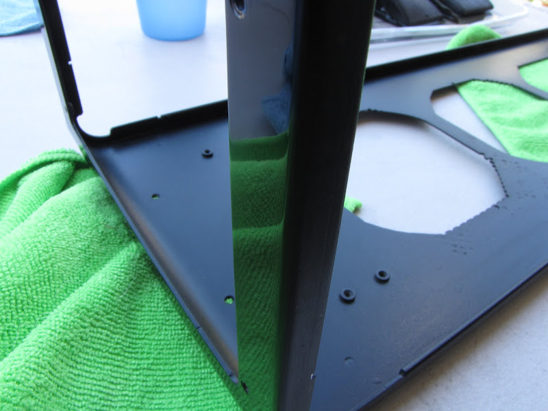
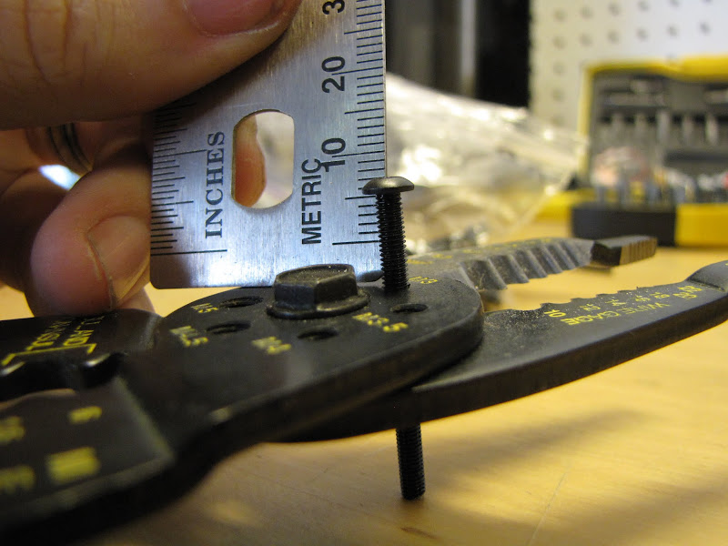
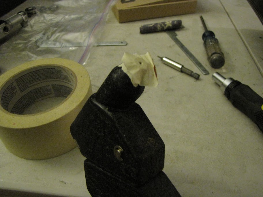
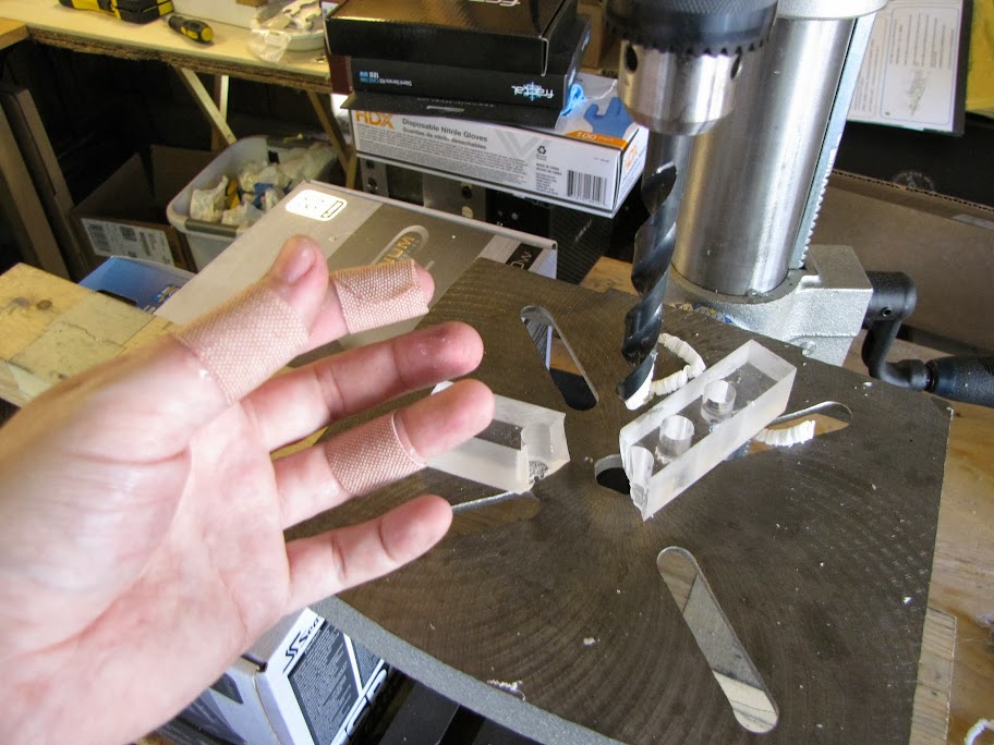
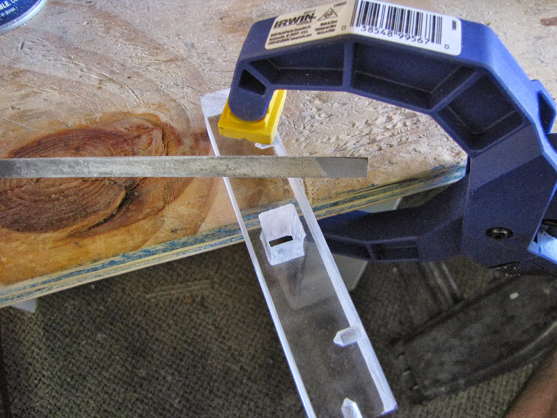
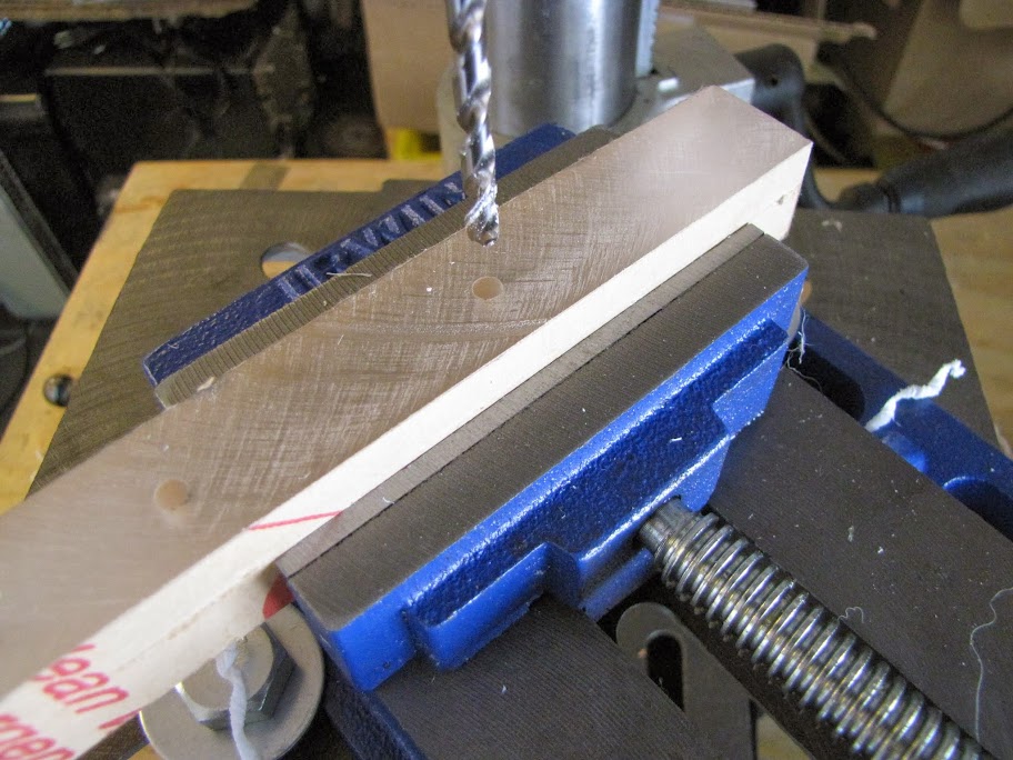
It took a bit of experimenting, but the process I worked out that more or less "guaranteed" that I didn't cut through the edges was to use my fingers along the edges like a "bumper" of sorts... like so:
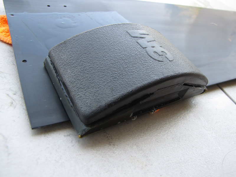
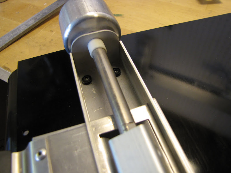
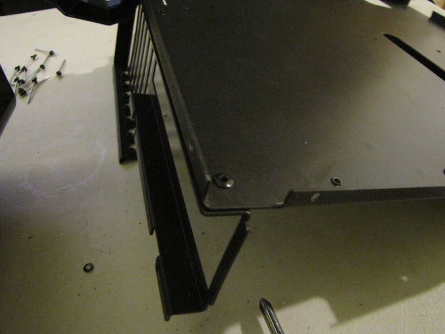
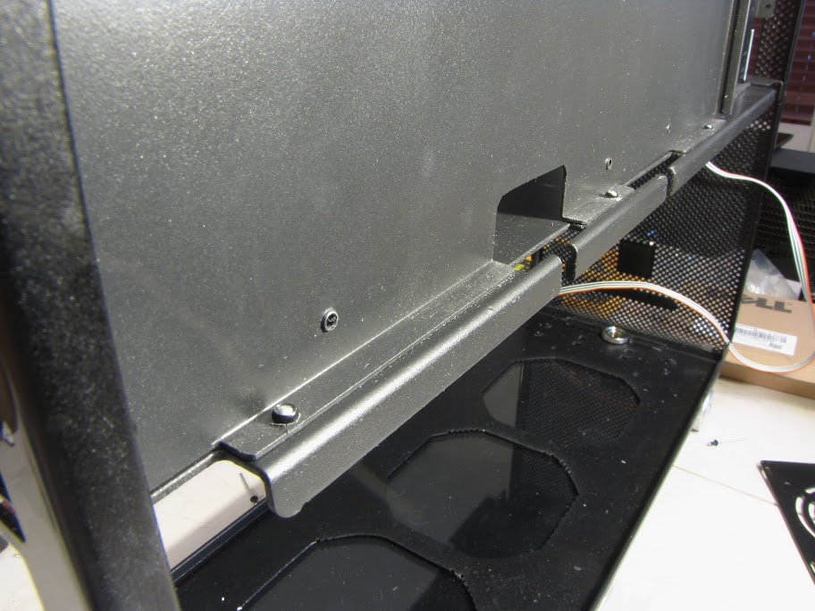
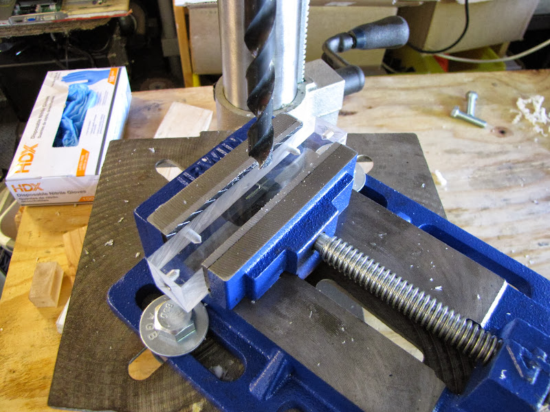
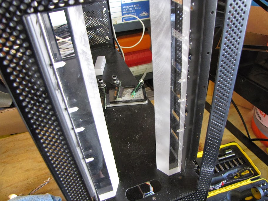
The other thing I did was make sure that I never pushed the sanding block over an edge that wasn't parallel to the direction I was sanding. So this is fine:
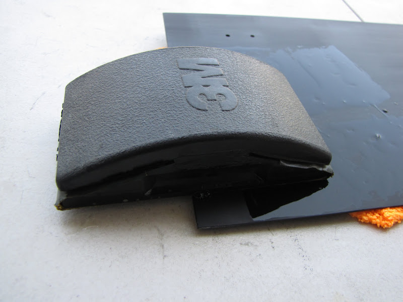
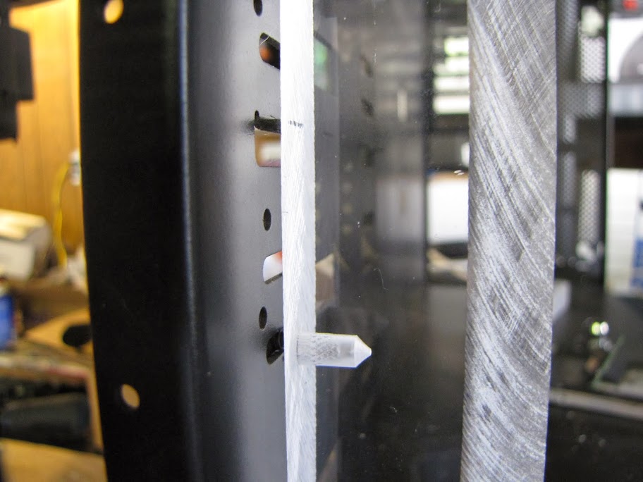
And this, is not! :p
Next, I switched to 1500 grit and changed directions. I went over the entire piece until I could no longer see the side to side marks from the previous sanding job with 1000 grit, meaning I had leveled out all the deep cuts.
No more cuts visible from the 1000 grit going side to side means I'm ready to move on:
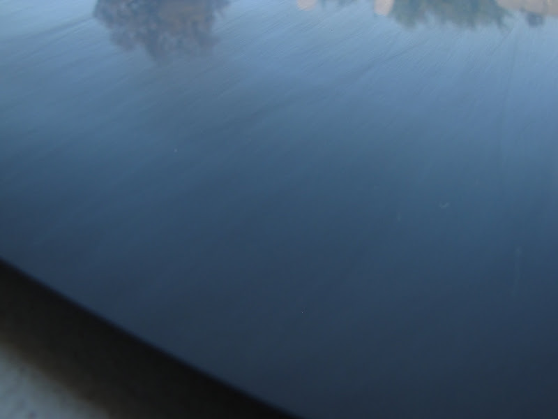
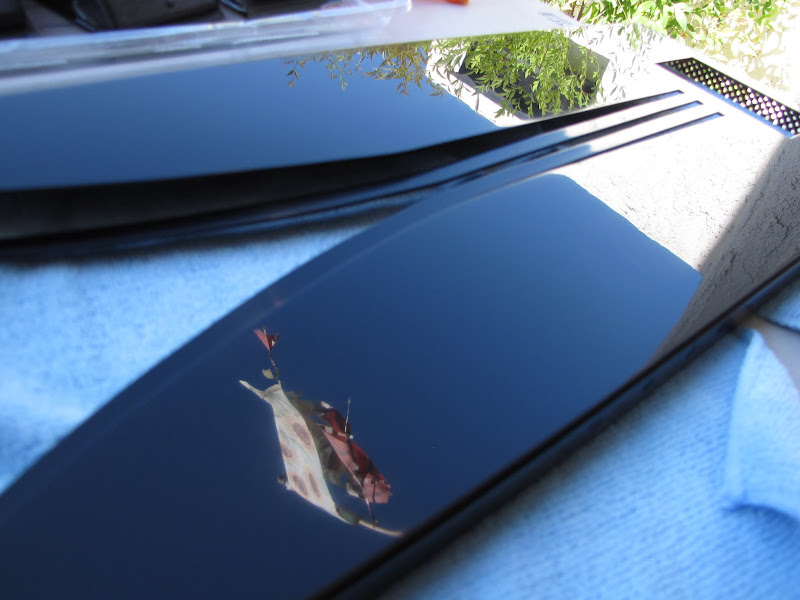
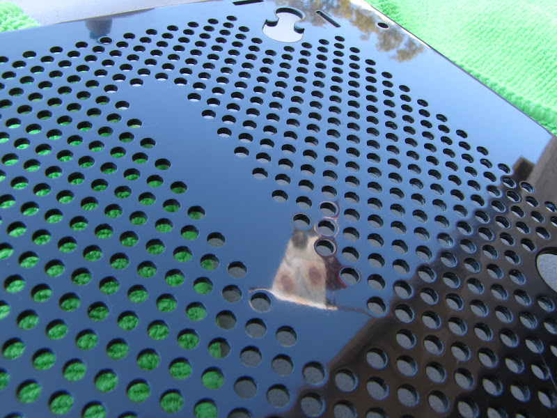
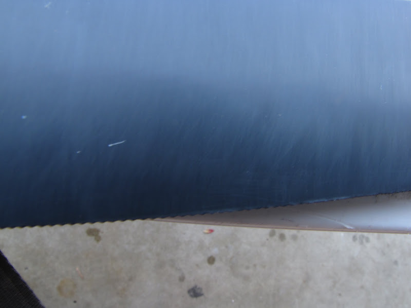
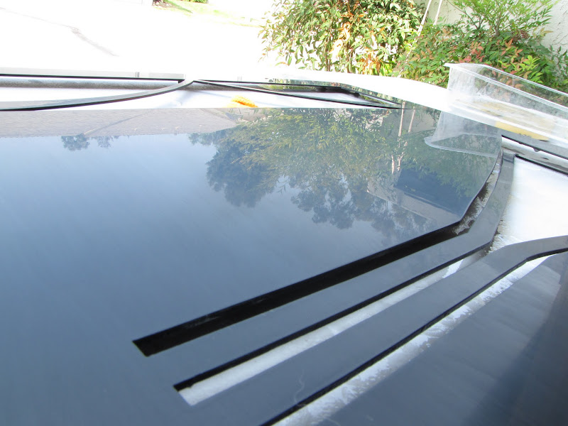
Next, I went over the whole piece again in 2000 grit, once again switching directions. You can see that I am starting to get a good reflection going at this point... but we're nowhere near done yet!
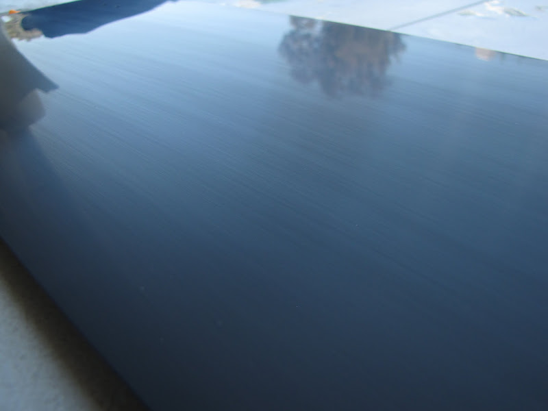
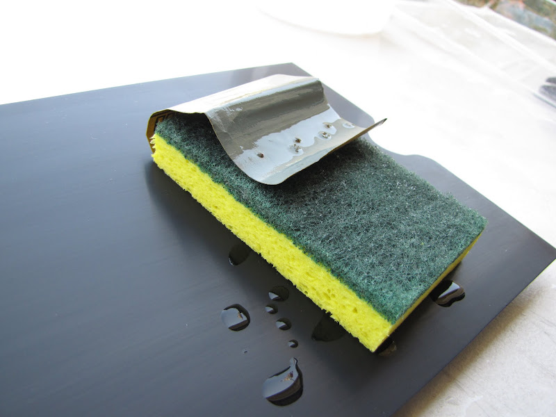
Once all the lines from 1500 were gone and only 2000 grit lines were left, it was time to move on to 2500 grit. I also switched from a rubber sanding block to a sponge with the sandpaper wrapped around. This helped cut down on the depth of the lines... but as a result took many more passes to get rid of all the 2000 grit lines:
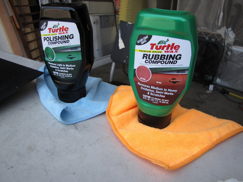
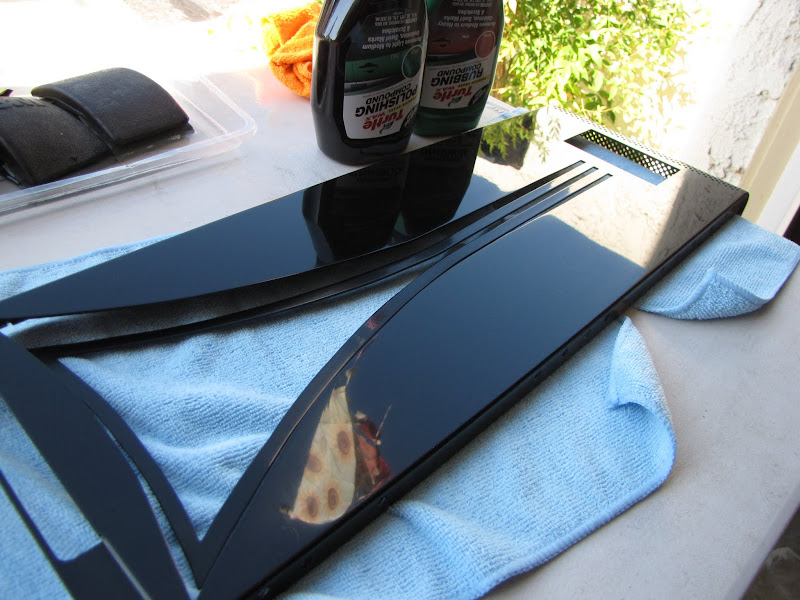
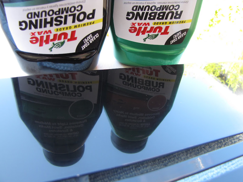
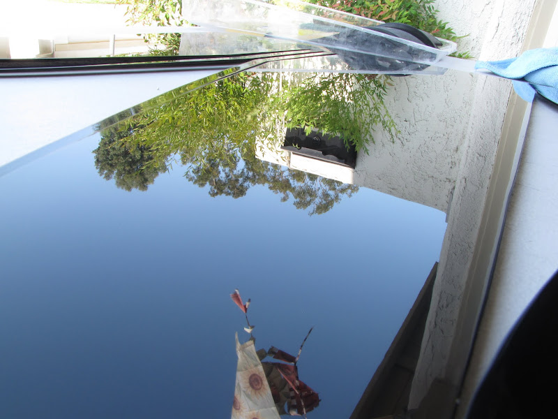
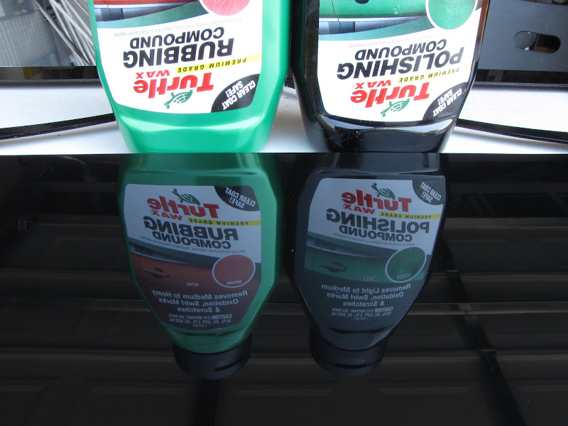
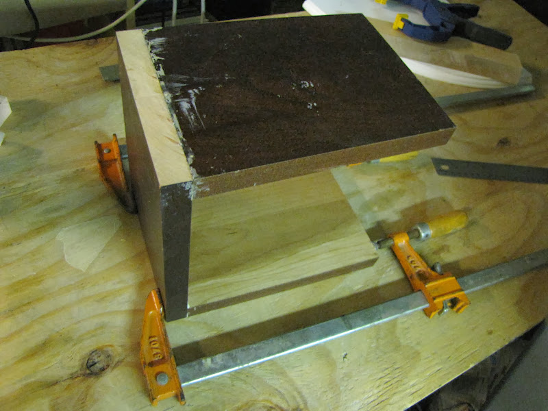
Looking even closer!Now, I moved on to some rubbing compound meant for renewing your finish on your car:
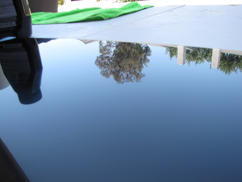
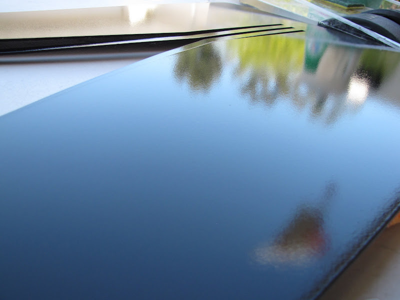
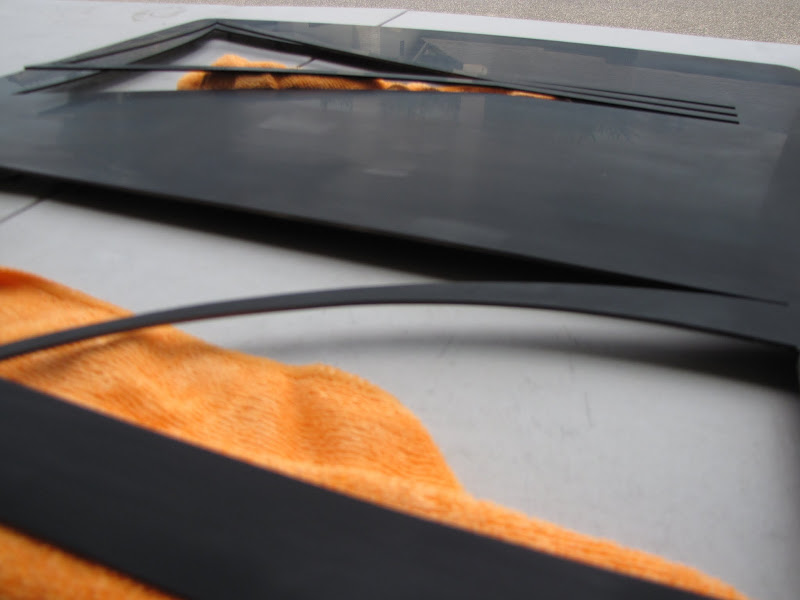
The rubbing compound has a bit more grit to it than the polishing compound, and does a better job of removing the scratches from the 2500 grit with less material required. I switched directions while using the rubbing compound one more time, going back and forth until no lines were visible from the 2500 grit. I used a microfiber cloth that I picked up at the automotive store I bought the rubbing compound and such from. I also used 'color coded' cloths so that I didn't mix up the cloth I used for rubbing compound from the one I used for polishing. I used one orange cloth to apply the the rubbing compound, and another clean orange one to remove the compound. I then used one blue to apply the polishing compound, and another blue one to remove the compound. The result:
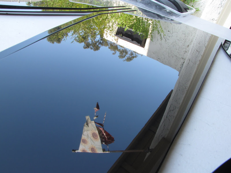
Perfect!
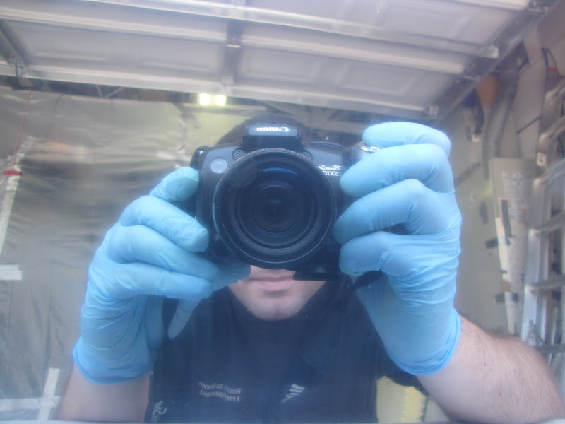
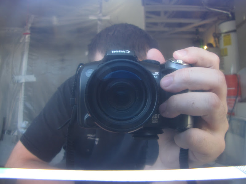
Hello there!
(It looks a little hazy, but that's because my shutter length / ISO wasn't quite right on my camera or something... it was hard to capture this picture... )
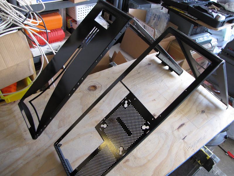
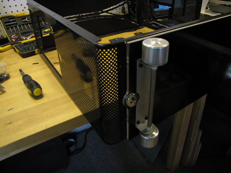
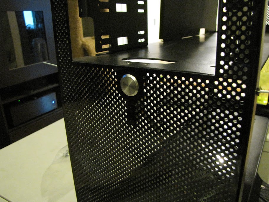
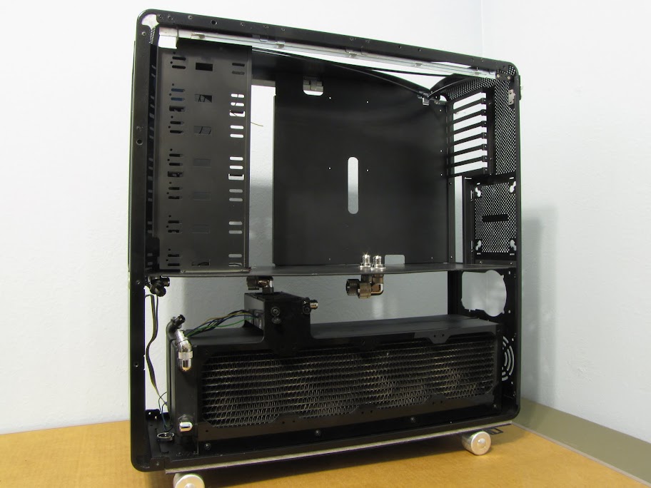
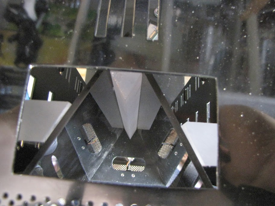
I then went on to give the same exact treatment to the top of my case:
Hooray! All that work is finally paying off. All in all, these two pieces took me about 6-7 hours. It's quite an extensive process, but most of what took so long was dealing with the complicated angles in the top of my case and such... it was very slow work trying to clean up all the edges in the design without cutting through. If you have a plain surface, it should go much faster!
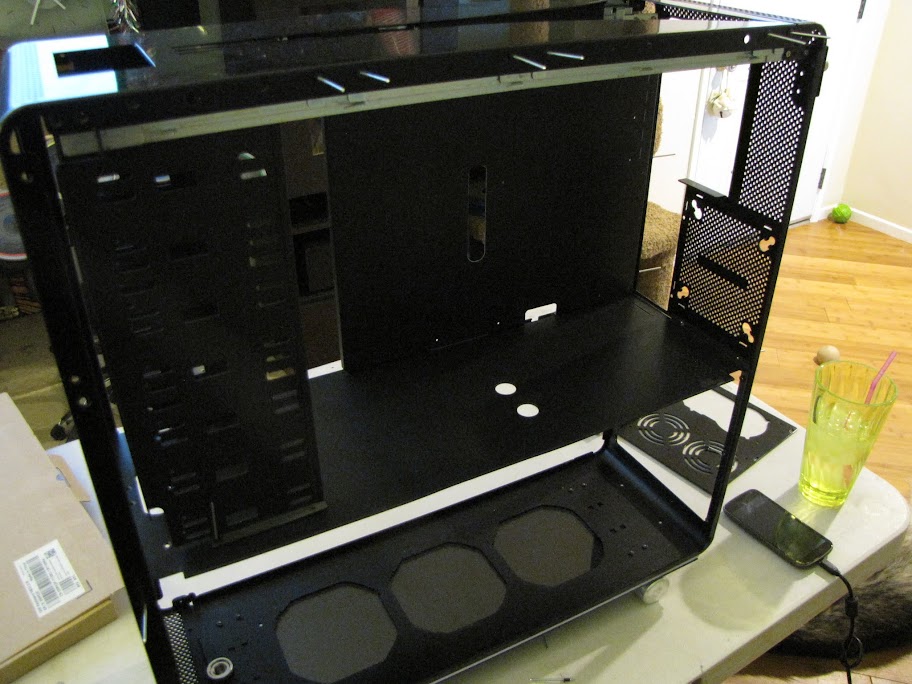
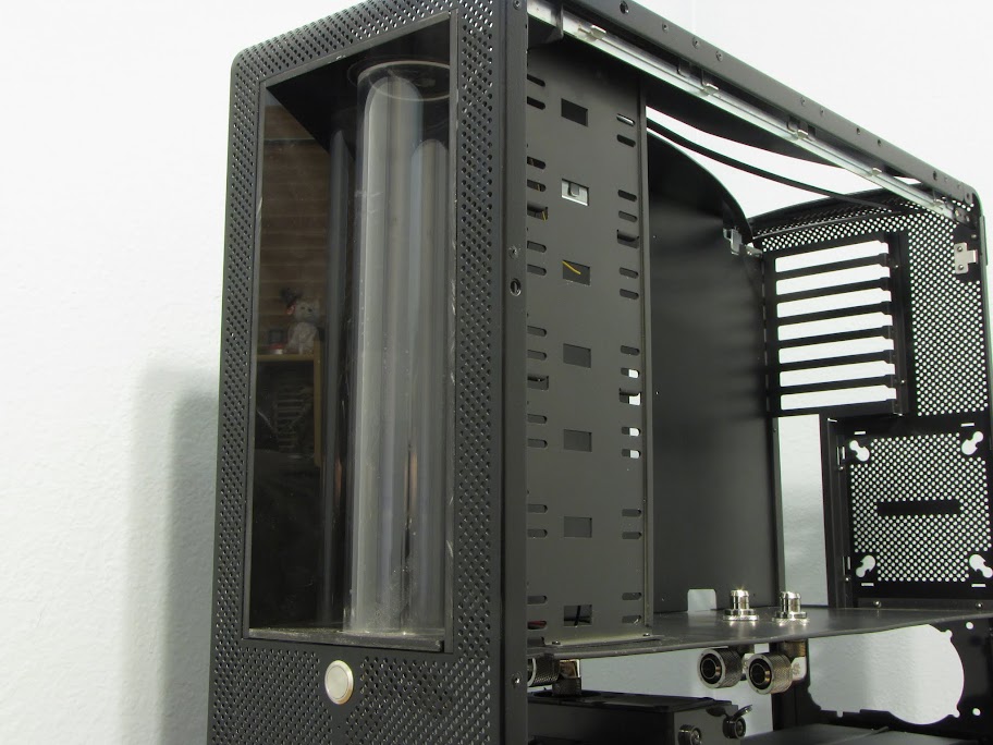
Now, I just have to give the same treatment to the two case doors, the other half of the case shell, and the PSU bracket. I'm hoping I'll get them all done next weekend, or maybe sometime into the week after! I have some time off, and I know what I'll be doing with it.
Until next time!


 Reply With Quote


 Work has been absolutely insane. But, I finally have a little time to myself... and where else would I spend it, but with updating everyone on my progress!
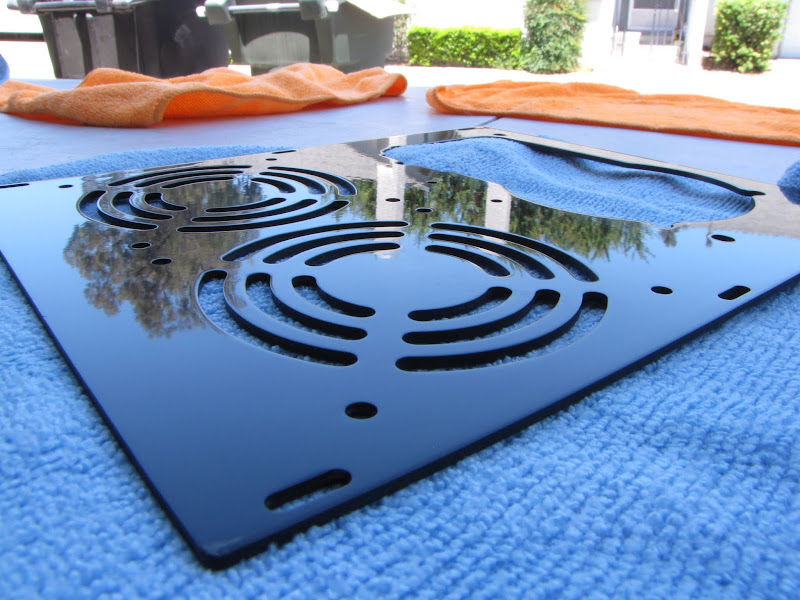


 Family and holidays will do that, I suppose. I've made a few tiny bits of progress that I will share, anyway! Hoping for a free day sometime soon so that I can keep moving on this... otherwise it's going to go on for 2 years instead of just 1!


Bookmarks