

Hahaha, you pretty much summed up my sentiments right there. Thanks!Originally Posted by paulbagz


Hahaha, you pretty much summed up my sentiments right there. Thanks!
EVGA z77 FTW -- 16GB of Samsung MV-3V4G3D/US -- Intel Core i7-3770k -- EVGA GTX680 -- Corsair AX850 PSU -- Lian-Li PC-v2000b -- 2x XSPC RX480 Rads -- EK-RES-250 -- EK-DDC Dual Top/pumps -- EK-FC680EN Full Cover block -- Swiftech Apogee HD Block
This comes to mind: "Gentlemen, we can rebuild him." In this case, your old PC.
\Project\ Triple Surround Fury
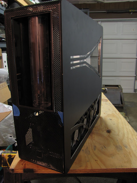
Case: Mountain Mods Ascension (modded)
CPU: i7 920 @ 4GHz + EK Supreme HF (plate #1)
GPU: GTX 670 3-Way SLI + XSPC Razor GTX670 water blocks
Mobo: ASUS Rampage III Extreme + EK FB R3E water block
RAM: 3x 2GB Mushkin Enhanced Ridgeback DDR3 @ 6-8-6-24 1T
SSD: Crucial M4 256GB, 0309 firmware
PSU: 2x Corsair HX1000s on separate circuits
LCD: 3x ASUS VW266H 26" Nvidia Surround @ 6030 x 1200
OS: Windows 7 64-bit Home Premium
Games: AoE II: HD, BF4, MKKE, MW2 via FourDeltaOne (Domination all day!)
Hehe, thanks! Hopefully it doesn't take me 6 million dollars to get there, though.
EVGA z77 FTW -- 16GB of Samsung MV-3V4G3D/US -- Intel Core i7-3770k -- EVGA GTX680 -- Corsair AX850 PSU -- Lian-Li PC-v2000b -- 2x XSPC RX480 Rads -- EK-RES-250 -- EK-DDC Dual Top/pumps -- EK-FC680EN Full Cover block -- Swiftech Apogee HD Block
And if it does?
\Project\ Triple Surround Fury
Case: Mountain Mods Ascension (modded)
CPU: i7 920 @ 4GHz + EK Supreme HF (plate #1)
GPU: GTX 670 3-Way SLI + XSPC Razor GTX670 water blocks
Mobo: ASUS Rampage III Extreme + EK FB R3E water block
RAM: 3x 2GB Mushkin Enhanced Ridgeback DDR3 @ 6-8-6-24 1T
SSD: Crucial M4 256GB, 0309 firmware
PSU: 2x Corsair HX1000s on separate circuits
LCD: 3x ASUS VW266H 26" Nvidia Surround @ 6030 x 1200
OS: Windows 7 64-bit Home Premium
Games: AoE II: HD, BF4, MKKE, MW2 via FourDeltaOne (Domination all day!)
Well, I'll either need one heck of a sponsor, or my 'completed by' date may need to be pushed back a few centuries.
EVGA z77 FTW -- 16GB of Samsung MV-3V4G3D/US -- Intel Core i7-3770k -- EVGA GTX680 -- Corsair AX850 PSU -- Lian-Li PC-v2000b -- 2x XSPC RX480 Rads -- EK-RES-250 -- EK-DDC Dual Top/pumps -- EK-FC680EN Full Cover block -- Swiftech Apogee HD Block
Can you imagine all of the crazy gear centuries from now?
\Project\ Triple Surround Fury
Case: Mountain Mods Ascension (modded)
CPU: i7 920 @ 4GHz + EK Supreme HF (plate #1)
GPU: GTX 670 3-Way SLI + XSPC Razor GTX670 water blocks
Mobo: ASUS Rampage III Extreme + EK FB R3E water block
RAM: 3x 2GB Mushkin Enhanced Ridgeback DDR3 @ 6-8-6-24 1T
SSD: Crucial M4 256GB, 0309 firmware
PSU: 2x Corsair HX1000s on separate circuits
LCD: 3x ASUS VW266H 26" Nvidia Surround @ 6030 x 1200
OS: Windows 7 64-bit Home Premium
Games: AoE II: HD, BF4, MKKE, MW2 via FourDeltaOne (Domination all day!)
I'd say yes, but I'd be completely wrong. Heck, we can't even properly imagine what will be available 10 years from now. Just compare what we had in 2000 to what we had now... nothing, that's what. :p
Anyway... Sorry for the delay in getting this post together! I meant to put it up this weekend, but my weekend ended up being a bit of a bust modding-wise. I spent all of Saturday putting up a fence in the rain for my dad, and Sunday shopping for xmas presents with the wife. Fortunately, I carved some time out this evening and still made some reasonable progress!
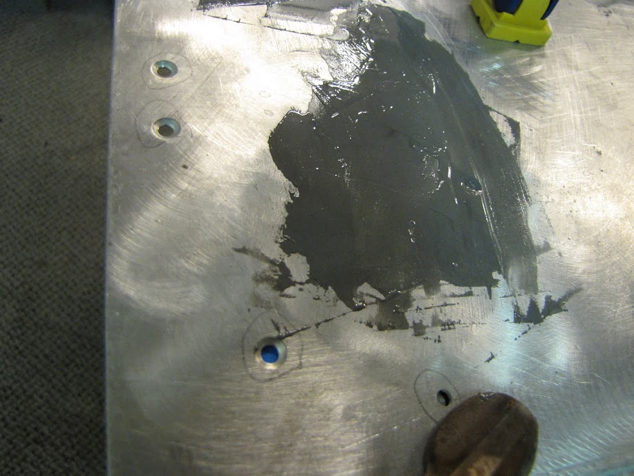
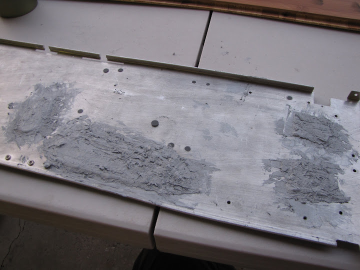
So, as I had indicated, I was in the process of repairing the bottom of the case from the large radiator holes cut out for the last cooling system this case housed. After testing out a few products, I landed on using some scrap aluminum to fit in the larger holes, then I used some Bondo bumper repair to put the whole thing together. This stuff is so incredibly versatile! Cheap, just flexible enough to avoid breaking under stress, tough enough to be drilled/tooled, sandable, etc etc. Has really been a pleasure to work with!
I started out with a fairly thick layer to fill holes and gaps. I decided to fill in all the air holes in the bottom of the case, along with the other miscellaneous holes that were originally for holding up the drive cages, partitions, etc.
I let that dry for a few minutes on top of a sheet of aluminum foil (which oddly it doesn't bond to, even though it bonds to my aluminum case just great...)
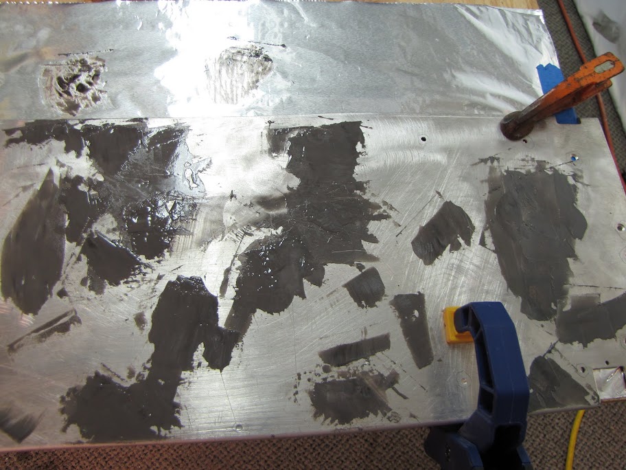
Then, a second coat of it to fill in the smaller gaps and imperfections in the first coat, giving a nice 'slurry seal' and leveling everything off:
I let that dry over night... then pulled off the foil and inspected the bottom side.
Just a little bit of seepage through the holes, not too bad though. Should be easy to sand off. I then went through and filled in any holes that didn't quite get filled from the back side, along with sealing any cracks around the aluminum plates and such:
Then, I let that dry for another 24 hours. You can probably see why this took so long.
Next day, I started sanding... oh... SO much sanding. This was an hour or so worth:
Turns out this stuff eats sandpaper alive. I went through all the sheets of 80 grit I had, then had to break and go to the store for more.
After finishing the first round of sanding to satisfaction, I went for a final 'top coat' of Bondo to seal in any pits and such.
24 more hours later... and a few hours of sanding with 120 grit...
And finally, the last pass of sanding with some 400 grit to remove the deeper grooves:
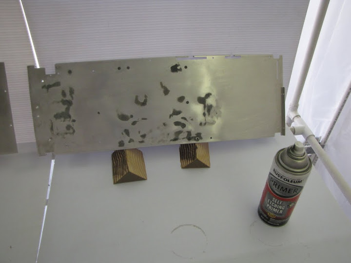
Man, what a production! But now the whole surface is baby's butt smooth, and should cover fairly nicely when I primer it.
And now, on to the next task, and the whole reason I repaired the bottom the way I did... so that I can mount my radiator housing on it!
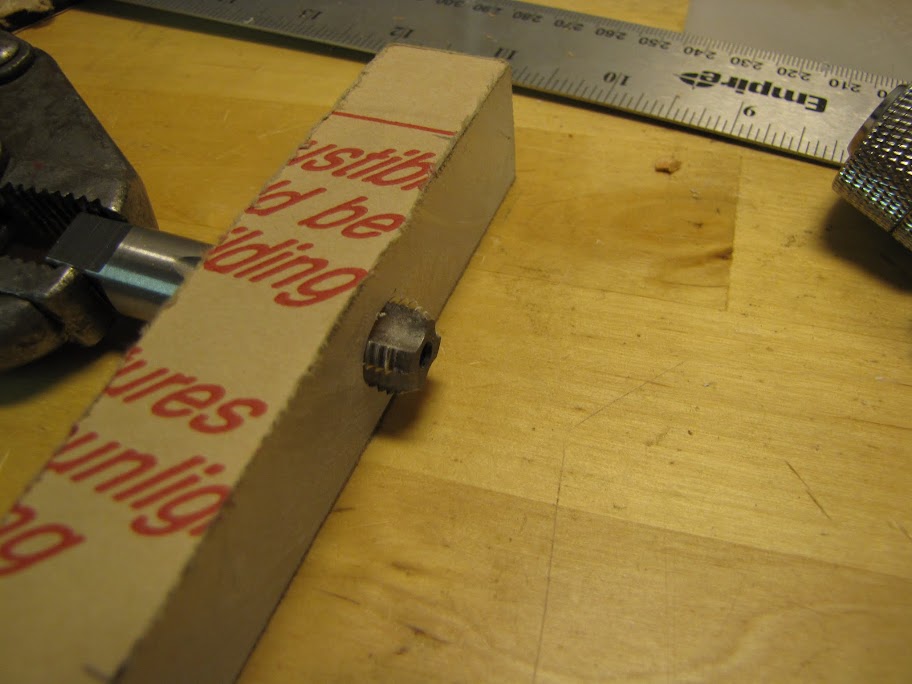
I started with a little planning and measuring. I decided I wanted to use the four 'spacer blocks' that keep the housing held together as the mounting points on the bottom of the case. Since the press-fit screw fittings worked out pretty well, why not use them again!
I taped off the bottom of the case... not so much to protect it, as to give myself a good drawing surface so that I could measure out all the points where I wanted to drill:
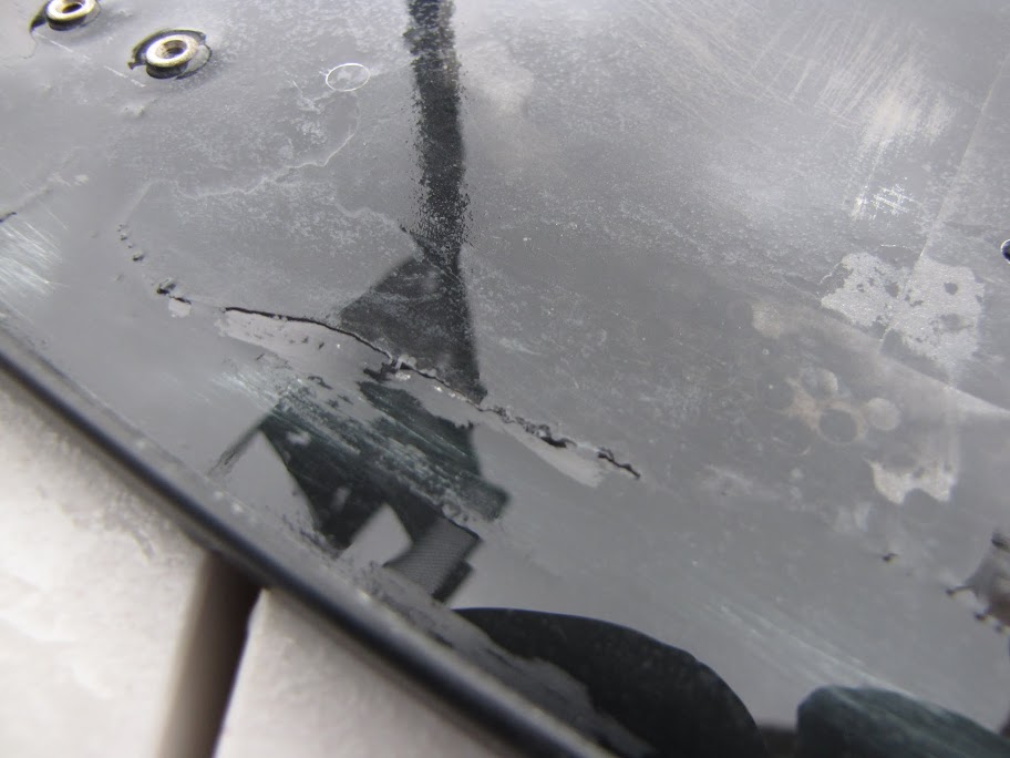
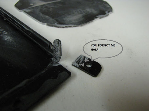
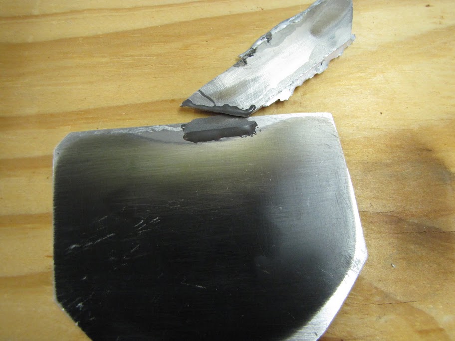
I tilted the thing up on it's side to press the tape on securely, and one of the little wing tabs that keeps the case together fell off... doh...Oh well, one more reason to use bondo!
It has good holding strength, but there's not a lot of surface area to work with here, so I am not so sure it will work. I may have to do an actual weld...
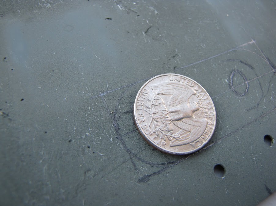
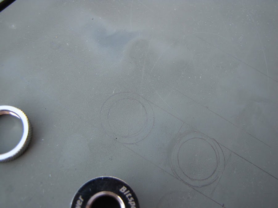
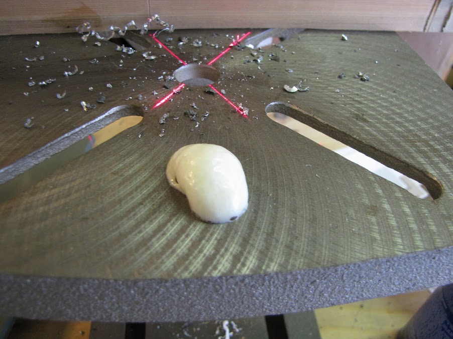
Anyway, I got the locations of the cross bars with respect to the bottom of the case all mapped out on the masking tape:
Then used the trusty drill press to punch the screw holes in the case...
There we go!
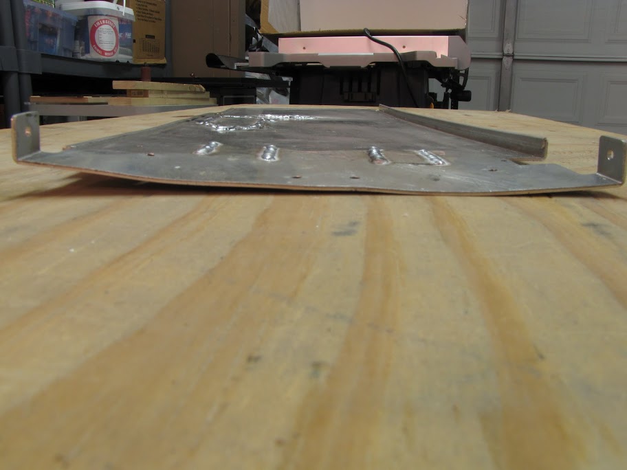
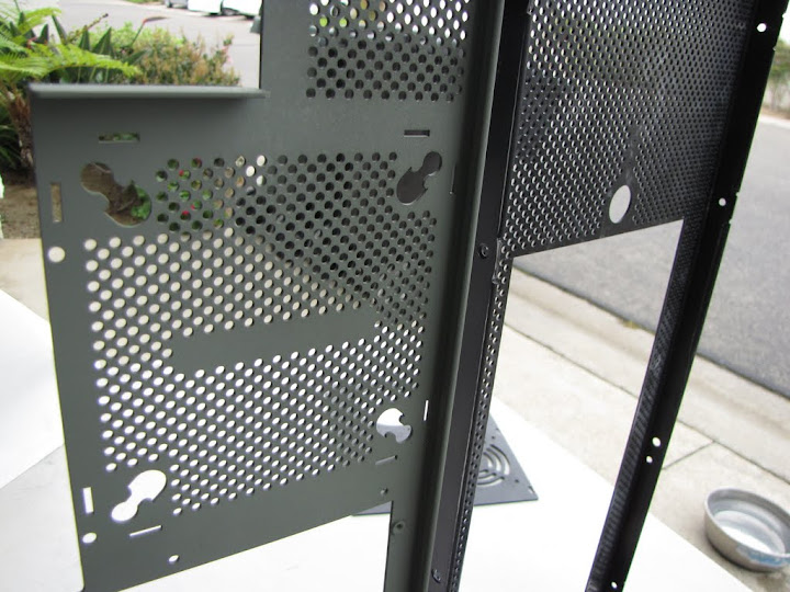
Maybe it's because it was getting late... or perhaps it was the epoxy fumes... but a little while after shooting the above photo... I realized that the plates and holes formed ridiculous faces. I couldn't stop looking at them every time I looked at the case...
:p
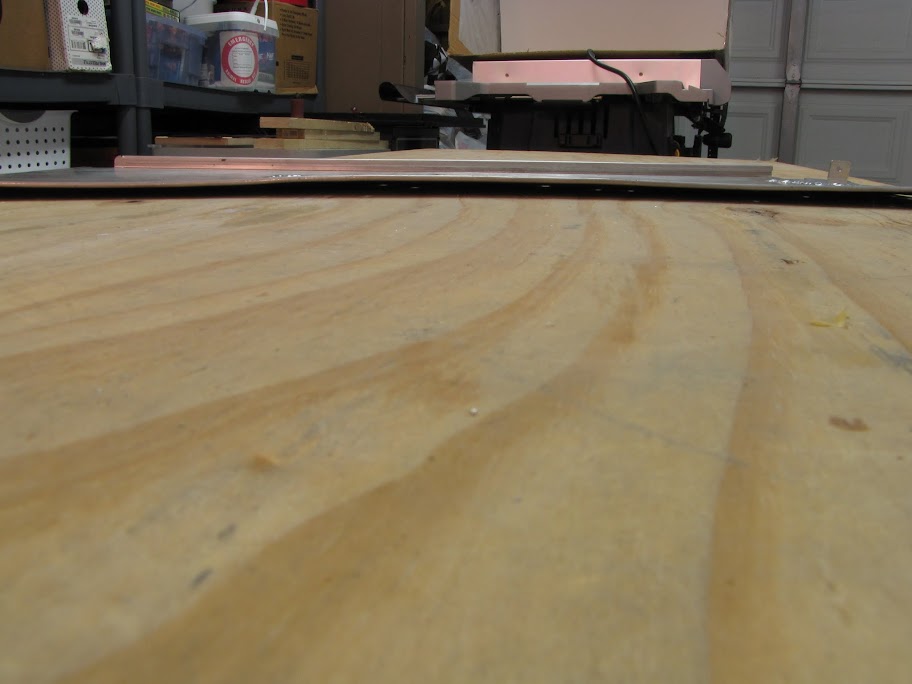
Anyway...
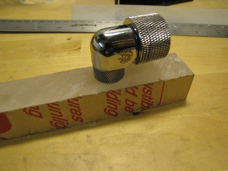
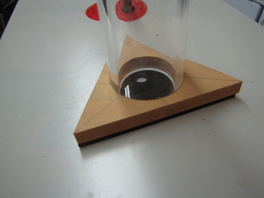
Now that I had the holes measured and drilled, I simply set the case on top of the radiator while upside down, and used a pencil to mark the hole placement on the acrylic blocks. A quick hit with the drill press, and a few taps of the hammer later:
And with some custom-cut MDPC screws/brainwashers:
Voila!
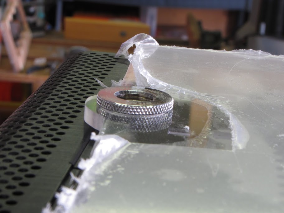
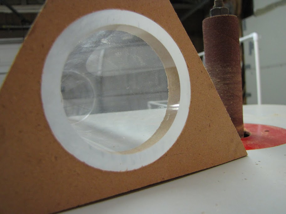
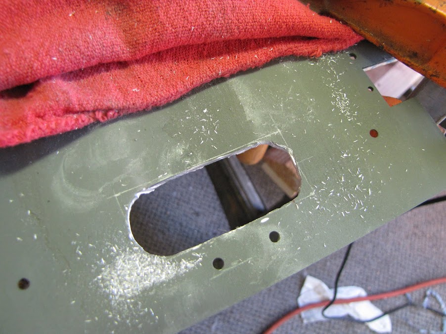
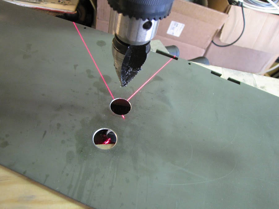
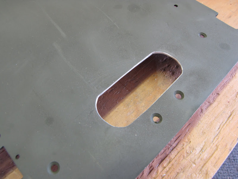
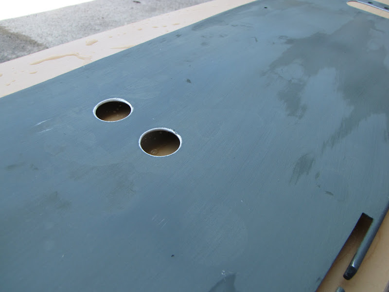
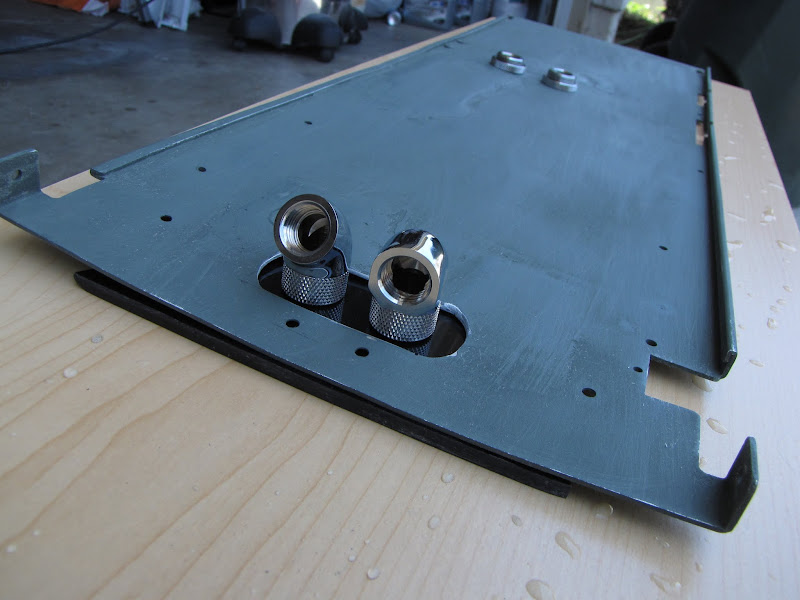
And now, for the final challenge, and the part I was most dreading... the fill port / drain port:
If the measurements end up just a tiny bit off, or something doesn't fit together quite right... I'm in for some major headaches down the road. I started off by setting it just like in the picture above, screwing the whole system to the case so that I was positive it was sitting exactly where it would be going in the final build, then traced an outline with a pencil. Then, I set to work with the trusty Dremel and my up-spiral routing bit:
So far so good... now for the other part of the case that slips into the slot you can see through the tape above. I assembled the case, then traced the complete circle again over the tab that was covering up a portion of the hole I cut out. A bit more Dremeling, and a sizable amount of filing later...
Bam! Perfect fit!
Phew! What a relief! Now I can sleep at night!
Until next time...

EVGA z77 FTW -- 16GB of Samsung MV-3V4G3D/US -- Intel Core i7-3770k -- EVGA GTX680 -- Corsair AX850 PSU -- Lian-Li PC-v2000b -- 2x XSPC RX480 Rads -- EK-RES-250 -- EK-DDC Dual Top/pumps -- EK-FC680EN Full Cover block -- Swiftech Apogee HD Block
Sometimes you must take a few steps backward in order to make a step forward. At least... that's what I keep telling myself after my latest disaster. /sigh
As anyone reading this log is well aware at this point, I was somewhat enamored with bondo for doing the small repairs on my aluminum case. Was. As it turns out, this stuff ended up not working so hot when I started preparing it for painting. More details below.
Anyway... I started out by fixing that little tab that fell of with some of my remaining steelstik:
I gave that a good few days to dry, as it's been cold and this stuff takes forever to dry cold.
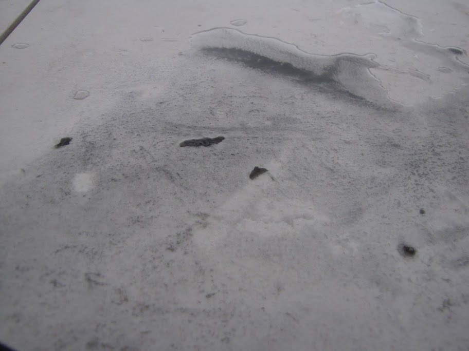
This weekend, I finally had some time to myself, and determined that I would get started with preparing and priming the case for painting! Exciting! Except... during the wet sanding:
Doh!I wasn't even being that rough... letting the P400 wet sandpaper just glide over it as the whole surface was pretty much finely sanded already. And yet... as I continued to sand, more and more of it bubbled up and peeled off:
So much for this stuff working on 'any surface.' Looks like it doesn't bond to aluminum so well.
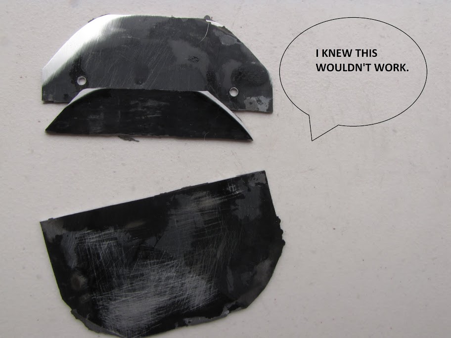
Anyway, I could tell at this point that the bondo was going to have to come off. And the more of it I removed, the weaker the bonds holding the plates got. I finally threw in the towel and punched the plates out, determined to find another way to repair the bottom of the case:
Back to square one... (maybe square -1, as now I have a mess to clean up too...
Shut up, you! Even my case-face grew an authoritative mustache just so that he could mock me with his superior knowledge of case repair.
Anyway, now I am looking at potential options for a more solid and permanent repair:
1) Find a local aluminum welding shop and see what it costs to get this repair done properly. I'm anticipating it will be too expensive, but who knows?
2) Try some other materials. I found some stuff called "Alumiweld" online that claims it can weld aluminum using just a blow-torch. Reviews online are mixed. The stuff is cheap, however.
3) Find a replacement Lian-Li PC-V2000 online. "Short supply" wouldn't even begin to describe the chances of finding one at this point... as they are very popular, and very old.
Anyway, I won't give up just because of this setback! It just might take me a little while to find a proper solution... stay tuned!
EVGA z77 FTW -- 16GB of Samsung MV-3V4G3D/US -- Intel Core i7-3770k -- EVGA GTX680 -- Corsair AX850 PSU -- Lian-Li PC-v2000b -- 2x XSPC RX480 Rads -- EK-RES-250 -- EK-DDC Dual Top/pumps -- EK-FC680EN Full Cover block -- Swiftech Apogee HD Block
Hello Everyone!
So, I moved forward with the plans to replace the bottom of my case with a new plate... but I decided to take it one step further and make a feature out of it! Sometimes missteps turn into opportunities!
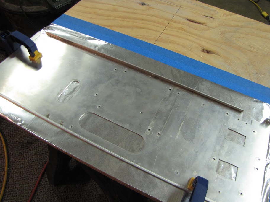
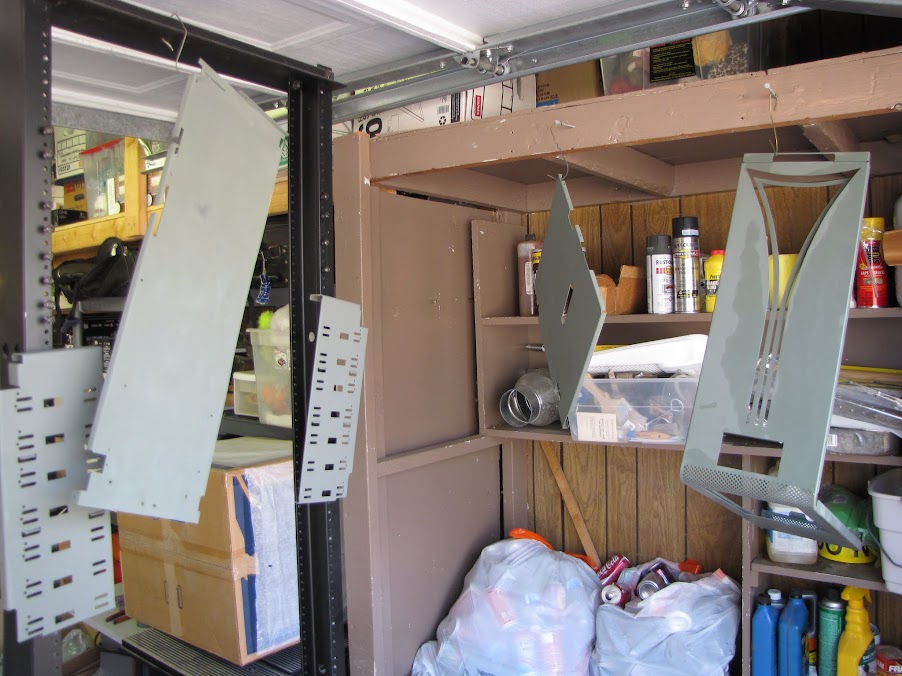
First of all, I managed to grab a piece of 2mm thick aluminum scrap from a friend. After playing with a few ideas, I decided I would bolt the piece to the bottom of the case, along with a 5mm thick piece of clear acrylic as a 'spacer'. I threw together a little 'proof of concept' piece out of some scraps I had first, as I didn't want to waste my clean aluminum piece on experimentation. There are a lot of things going on along the bottom of the case... I have wheels to attach, a drain port that comes through the front of the case, and several screws to hold the radiators to the case. After several iterations, I decided I liked this layout the best:
With that all worked out, I sized up a clear piece of acrylic for the bottom of the case, and drew a line where the edge of the acrylic would be. I would have liked to keep the whole ledge out to the depth shown in the picture below, but the case won't reassemble with that ledge sticking over the perforated area:
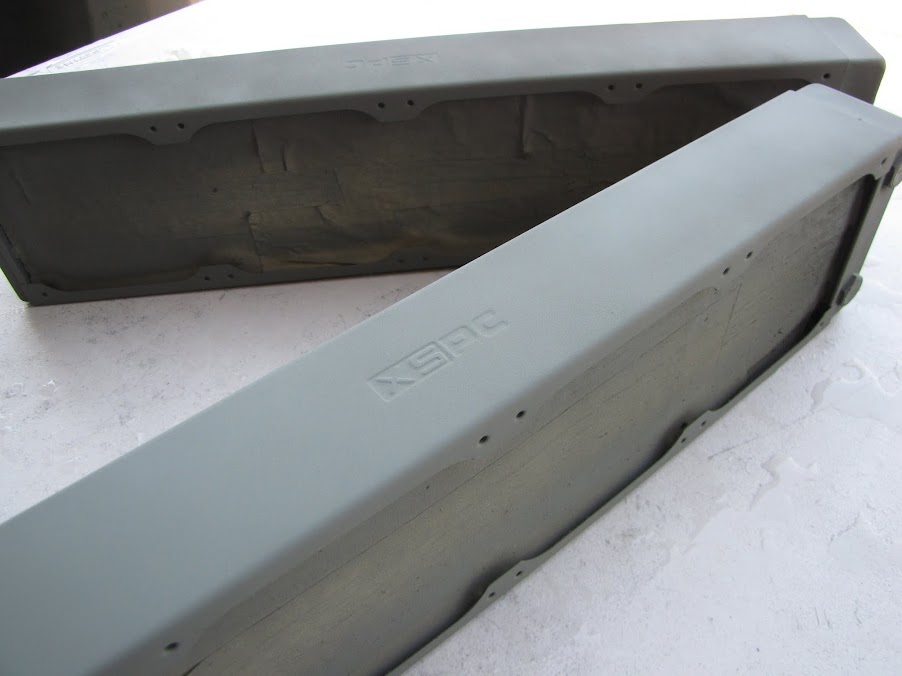
Next, I lined up and trimmed the aluminum piece to match the planned edge of the acrylic:
After some fiddling, I decided it would likely work out best if I created a template out of MDF for the front area. The drain port will be surrounded by a thin rim of acrylic, which will be a bit too fragile to do by hand...
A quick pass on the router later:
After that, I used my unibit and the drill press to punch a hole for the drain port in it, and tested the assembly:
So far so good! Next, I carved a hole in the aluminum plate to match the outer diameter of the acrylic rim around the drain port using my jigsaw and a metal file:
Okay... but not quite right. I consulted with a few friends that were over at the time, and ended up with this design:
Much better! More fluid and appealing. (Yes, I know the acrylic isn't quite centered in this pic... I'm going to make some final adjustments during wet sanding!)
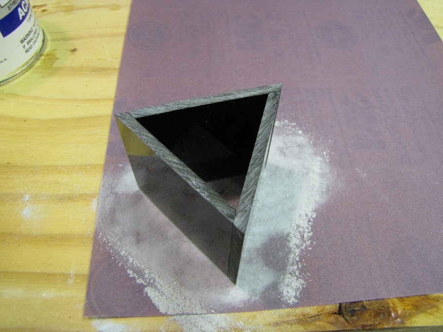
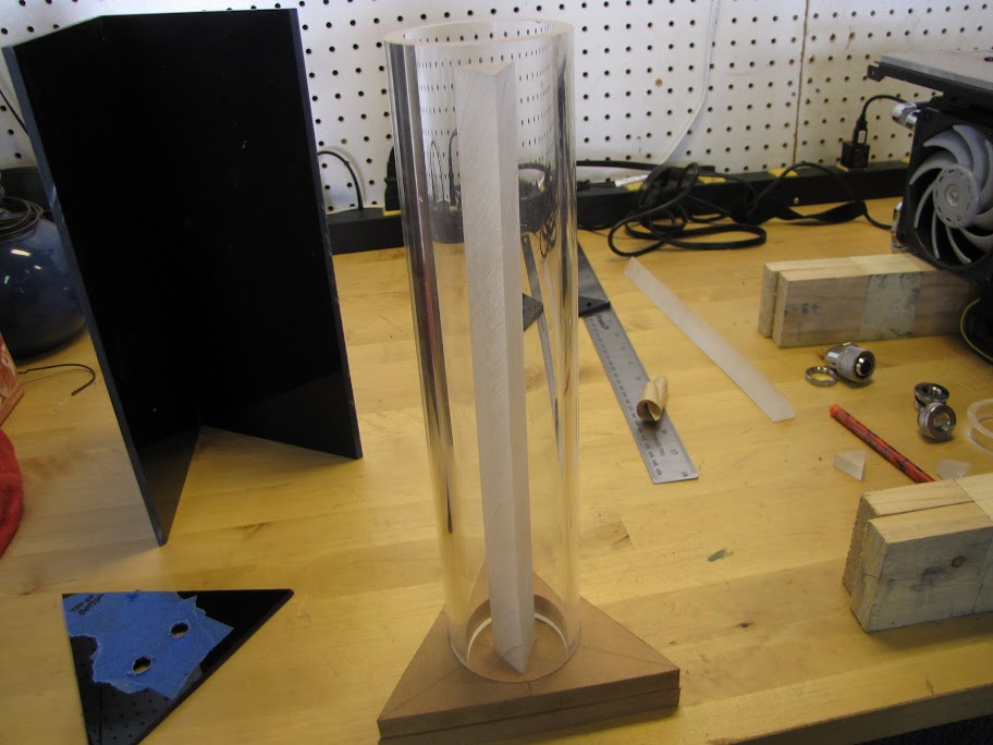
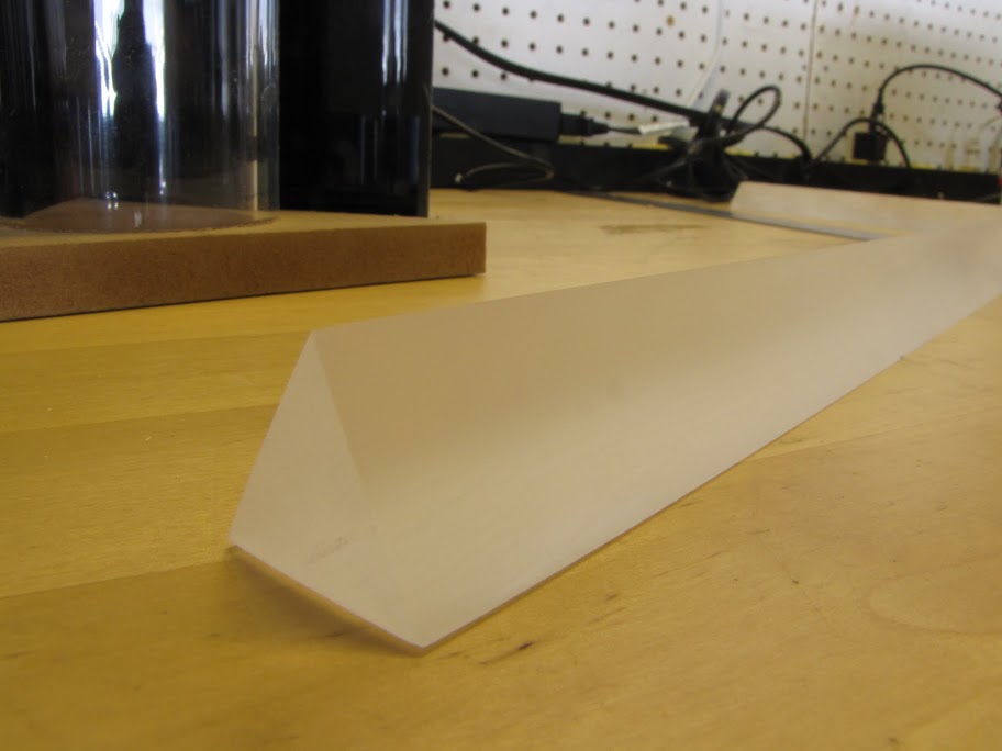
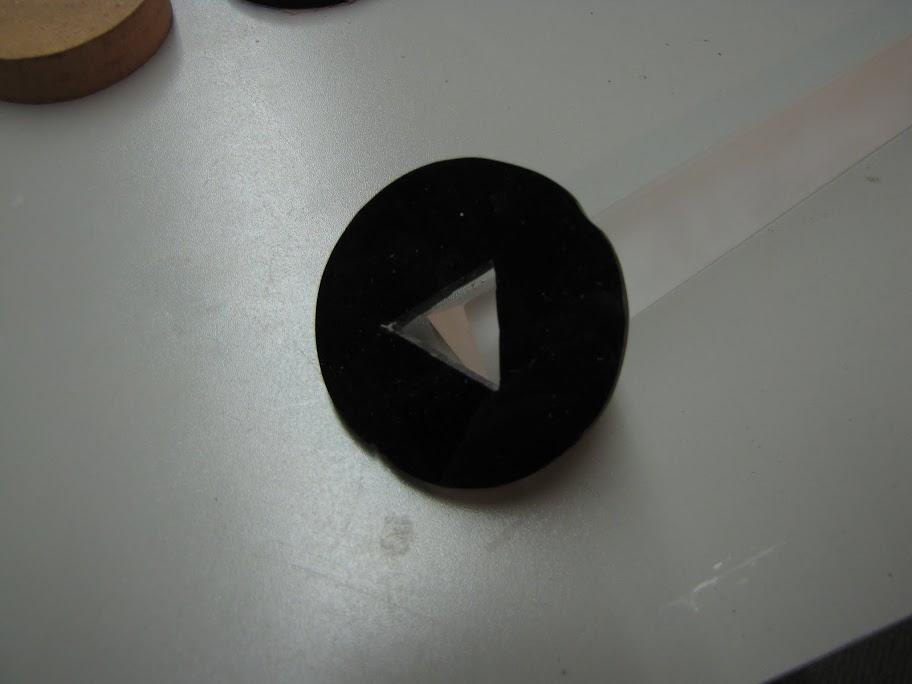
After that, I took a brief brake from that piece to quickly cut out a 'prism' for the center of my reservoir:
I had hoped that I could make a hollow version to put some lights in the center of, but there ended up not being enough space... so I'll be playing around with my options here, as I would like to really illuminate that prism.
After that, I played with the LED light / Arduino side of things. I mentioned quite a while back, but I have a friend developing a custom LED controller out of an Arduino uno, and he's made some good progress.
What I was thinking of doing was using one or two strips placed inlaid between the aluminum plate and the acrylic plate to light up the edges, giving a neat glowing effect between the two (eventually black) plates. Here's a very early preview of that, just for fun.
The shot is dark (intentionally), but what you are looking at is the aluminum plate on the bottom, the acrylic on top of that, and the bottom of the case on top, with the radiator block sitting on top of that. I simply smooshed the LED strip between the acrylic and the bottom of the case for now, but ill be carving an inlay soon that hopefully will give off better light on the edges.
Also, here's a quick video to give a better idea of what it looks like: http://youtu.be/gmVg79SDWlE
Until next time!
EVGA z77 FTW -- 16GB of Samsung MV-3V4G3D/US -- Intel Core i7-3770k -- EVGA GTX680 -- Corsair AX850 PSU -- Lian-Li PC-v2000b -- 2x XSPC RX480 Rads -- EK-RES-250 -- EK-DDC Dual Top/pumps -- EK-FC680EN Full Cover block -- Swiftech Apogee HD Block
Hope everyone had a nice Christmas / New Year holiday! I spent a lot of time with family over the last two weeks... so I only had bits and pieces of time to work on Prism. None the less... I made some progress! Here's what's been going on in the workshop over the past few weeks:
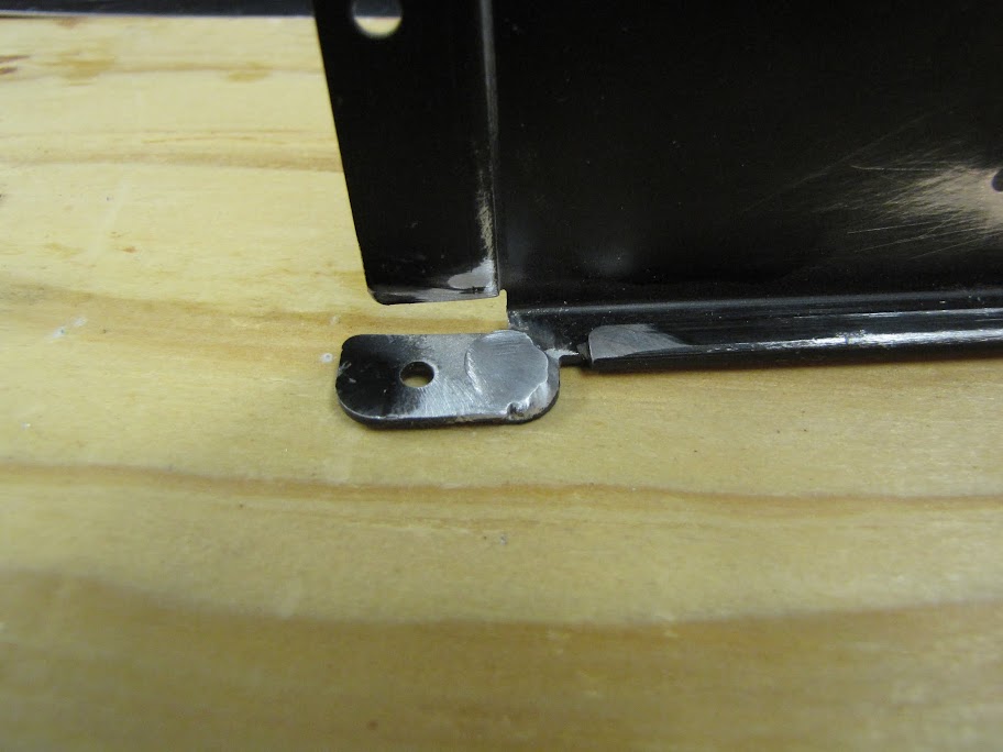
After the spectacular failures with bondo, I opted to address the holes in the bottom of the case with a plate and some acrylic as shown in my last post... but what I didn't address was the sad little rivet tab that broke off while messing with the case.
Yes... what to do about him. Bondo clearly isn't working, and I've tried some of the other similar products like SteelStik and such, but they just don't have the holding strength for a piece that needs to withstand riveting. The case will be very heavy when all is said and done, too, and the last thing I need is for this to snap and fall apart post-assembly. One option left...
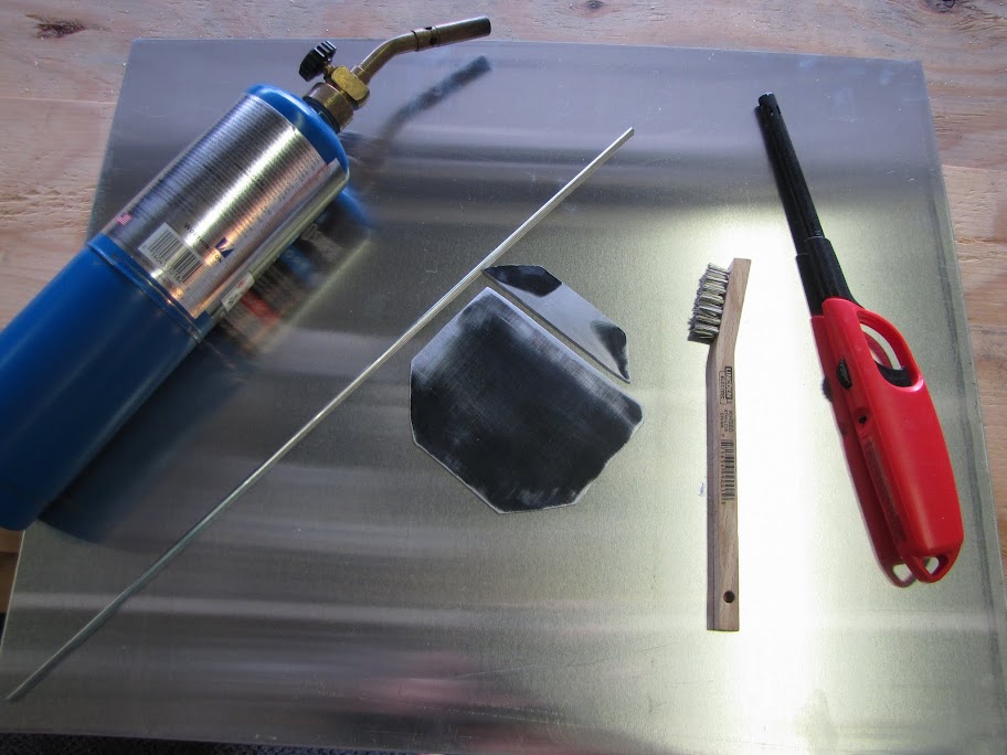
Welding.
Unfortunately... I don't quite have the budget for a MIG or nicer TIG welder... and no friends that have one nearby (yet)... so I looked around for some solutions. What I landed on was this stuff called "Alumiweld" that you can supposedly use at lower temperatures (730F) to weld aluminum together. It also just so happened that my local hardware had a package of the stuff for only $15... so what the heck? Worth a try.
Since this was a 2-handed operation, I didn't really take any pictures of the process... but here are the first attempts on some 'scrap' metal:
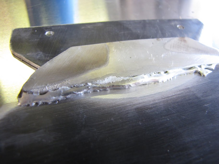
... Kinda ugly.
Anyway, I broke that weld... but no time to complain, time to try again!
Looks better... but...
Either I have herculean strength, or this stuff isn't holding at all. I have a feeling that I am not heating up the base aluminum enough. The smaller piece that I am welding on is getting so hot it is practically molten... but the base doesn't seem to be melting enough to mix with the alumiweld at all. I tried a few times after this without much success either... not sure what I am doing wrong.
One thing I did notice is that I was clamping down these two pieces so that they would stay in place using some steel bench clamps. These clamps were getting very hot... I think they might have been drawing heat away from the aluminum pieces. As soon as I took them off, the pieces would heat up much faster... but they were way harder to work with then, as the small pieces would just scoot around any time I tried to prod them with the Alumiweld.
Oh well... for $15, it was worth a try!
One last resort $5 attempt with another cold-weld adhesive that seems to have good reviews:
And...
Fail!
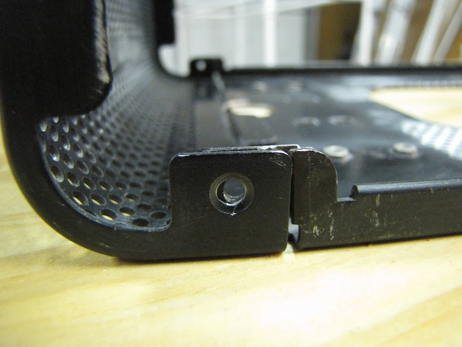
I found a nice little mom & pop welding shop nearby, showed them my work so far and what needed to be done, and they were happy to do a one-time small job for me at a very affordable price (only $35!):
Much better... that little tab isn't going ANYWHERE now. Considering how thin the aluminum is, and the fact that its a weird angle... they did a very good job I think. Definitely be heading back there for any other small needs. The guy did a remarkably good job lining the tab up with where it needed to be, also... only a tiny bit off of perfect:
Nothing a little Dremel work can't solve.
So... that's that for the case repairs (hopefully!) Now I can focus on other things... like the reservoir!
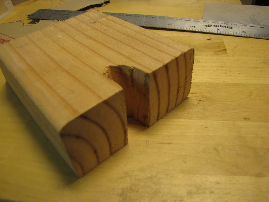
I bought a kit online a while ago to let me tap my own G1/4 ports for building the reservoir... but never really got to mess with it until now. As always, I don't trust myself with new tools, so I set out to practice a bit on some scraps. I started by putting the drill bit into my drill press for making the initial holes in some 5mm thick acrylic.
First problem... the drill bit I got seems to like to 'explode' acrylic... it's clearly not really meant for it like my acrylic bits are. It's a general purpose bit, so I think it is more for wood and metal. I got it to work eventually without shattering the acrylic by slowing the press down to about 800 rpm, and using a liberal amount of spray lubricant between 3-4 second pulses of the drill press.
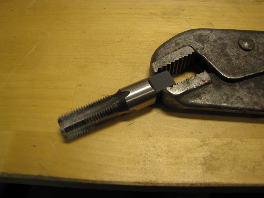
Next problem... I realized I don't have any kind of tool for the actual tap... because it's huge! I have plenty of tap kits for smaller bits, but nothing would fit this monster. I thought for a while, and looked around online for a good tool, but ended up with a fairly cheap solution:
The obvious problem with this approach was getting strait taps. This will be especially important since it needs to seal perfectly... it will be on the bottom of my reservoir! A few shots at eyeballing it revealed this was a hopeless endeavor. I needed a tool... but what? Then an idea hit me... why not make a guide that is sure to work?
First, I cut a chunk out of a scrap 2x4 piece of wood I had laying around that was about the size of the G1/4 tap bit:
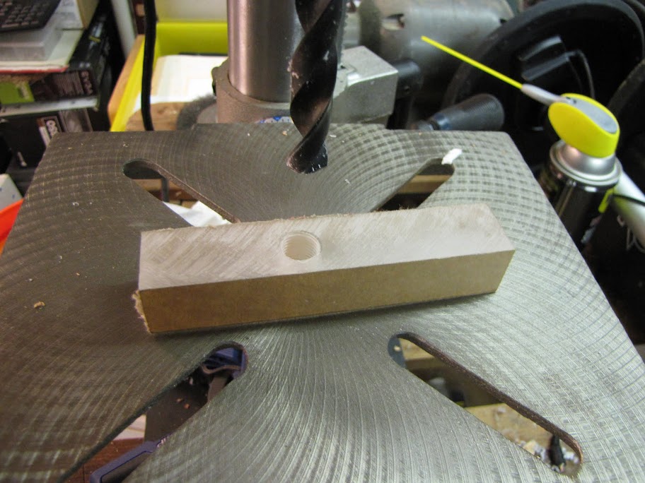
Next, I took a spare 1" thick piece of acrylic I had left over from the bottom of the radiator housing and drilled a hole in it:
I set up the contraption like so:
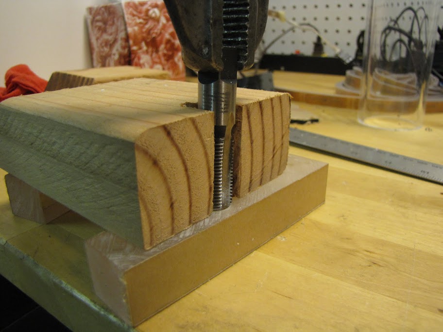
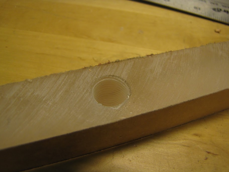
... and then tapped the full 1" piece of acrylic. The wooden guide helped make sure I was more or less strait, and as I put the tap through the entire piece of acrylic, it gradually straitened itself out to be perfectly strait, due to the drill press drilling a perfectly strait hole. When the tap went all the way through the block, it had about 5mm sticking out the back side of it:
There we go. Now I have a guide tool! Now, when I want to tap a perfectly strait G1/4 tap, all I have to do is set this guide piece on top of the hole I want to tap, run the tap all the way through the guide piece, and the little bottom piece sticking out in the picture above will start to tap the actual piece of acrylic that I want to tap. Easy peasy, no tool necessary!
See you next time! I plan on doing a bit more work on the reservoir, maybe a little detail work on the radiator housing... and maybe if I have enough time I can get to priming my case.Thanks for reading!
EVGA z77 FTW -- 16GB of Samsung MV-3V4G3D/US -- Intel Core i7-3770k -- EVGA GTX680 -- Corsair AX850 PSU -- Lian-Li PC-v2000b -- 2x XSPC RX480 Rads -- EK-RES-250 -- EK-DDC Dual Top/pumps -- EK-FC680EN Full Cover block -- Swiftech Apogee HD Block
Sub'd!
LOL, I find the images of the silly faces quite hilarious. They were unexpected. AND THIS, THIS IS WHAT I ENJOY IN A BUILD LOG!!!!!!!!
\Project\ Triple Surround Fury
Case: Mountain Mods Ascension (modded)
CPU: i7 920 @ 4GHz + EK Supreme HF (plate #1)
GPU: GTX 670 3-Way SLI + XSPC Razor GTX670 water blocks
Mobo: ASUS Rampage III Extreme + EK FB R3E water block
RAM: 3x 2GB Mushkin Enhanced Ridgeback DDR3 @ 6-8-6-24 1T
SSD: Crucial M4 256GB, 0309 firmware
PSU: 2x Corsair HX1000s on separate circuits
LCD: 3x ASUS VW266H 26" Nvidia Surround @ 6030 x 1200
OS: Windows 7 64-bit Home Premium
Games: AoE II: HD, BF4, MKKE, MW2 via FourDeltaOne (Domination all day!)
Hello!
Lots of good things happening right now, and I finally feel like I'm hitting a stride as far as making progress towards completion. It's all starting to come together!
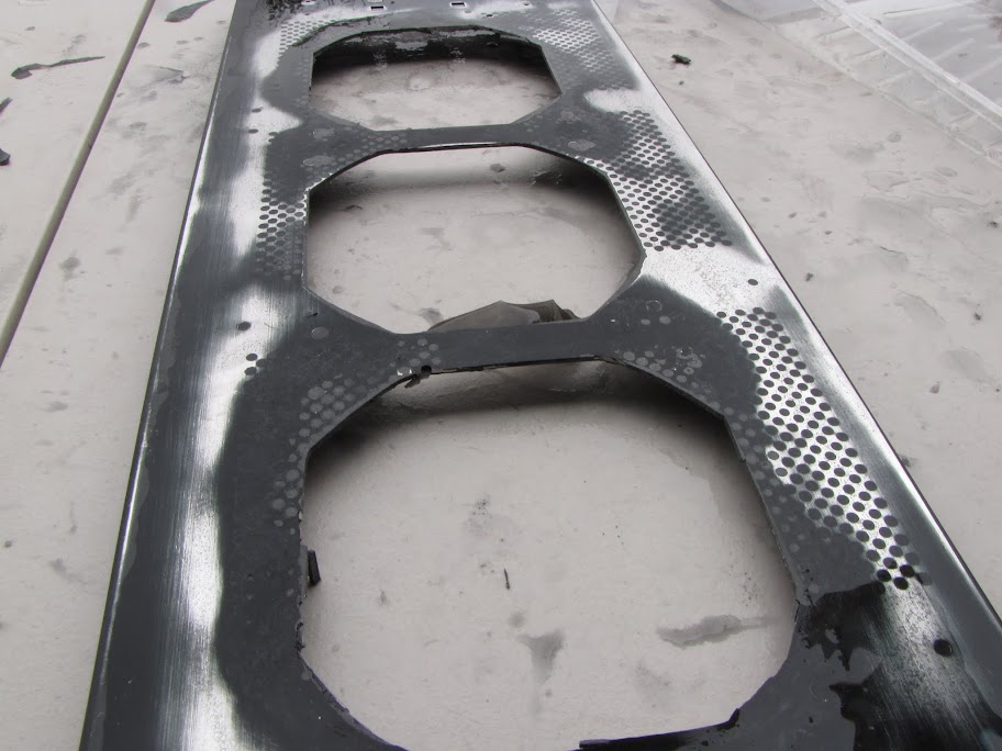
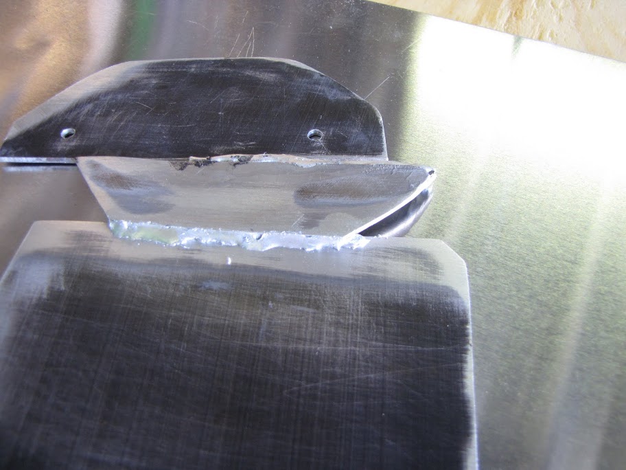
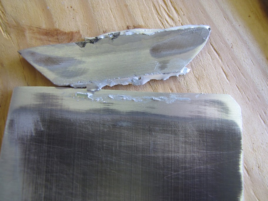
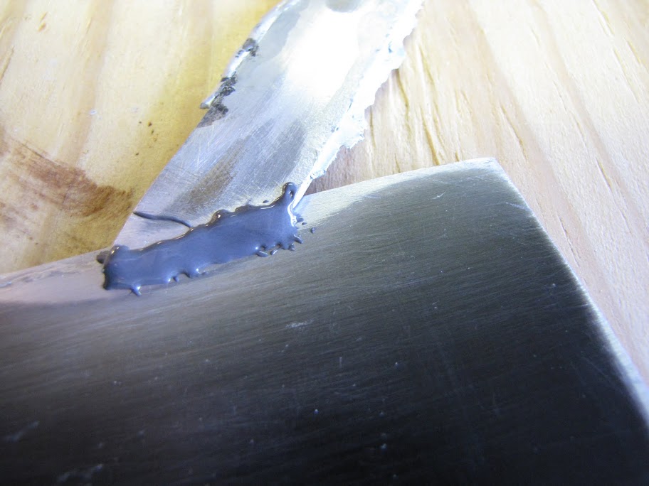
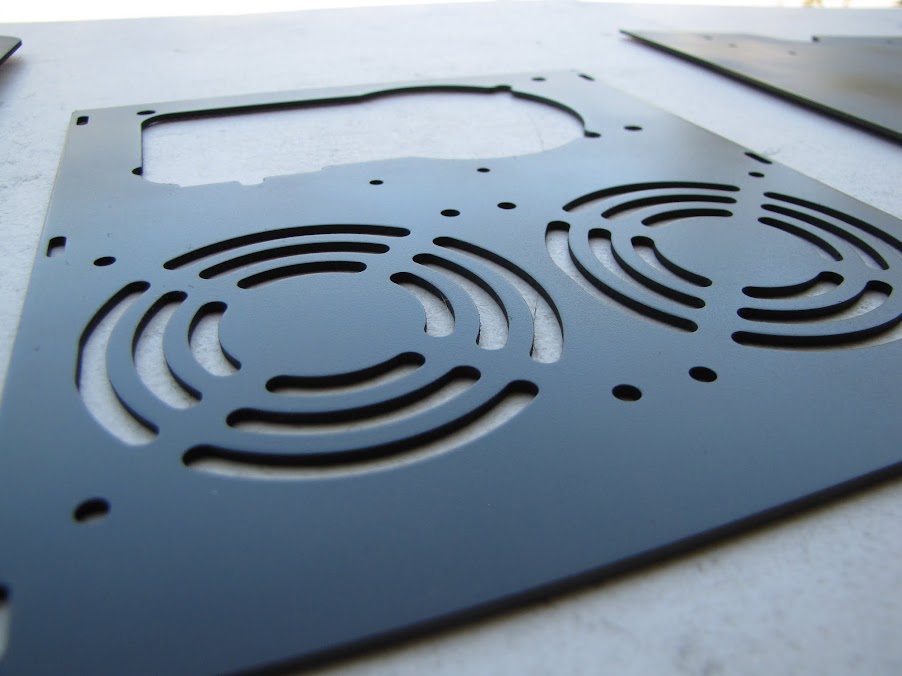
First of all, I decided I wanted to start on the repairs of my midplate. The plate came stock with a few large gaps for passing cables between the lower section (where the power supply and hard drives are supposed to be located) and the upper section (where the motherboard, etc. is located.) These holes are in a very front-and-center location though, and I think it ruins the aesthetic of the display window since they will literally be right in front of it. Also, from the previous very simple mod, I had cut two holes up towards the front for my tubing to pass through. So... I laid it out to try and figure out how I wanted to fix it:
I played with the idea of using JBWeld... but I was concerned I would just get burned again like I did with the Bondo. After all, I used a JB Weld product (the steelstick) too, and that didn't hold up either. I also considered using some of that low temperature welding stuff... but considering how well that went, I just decided to take it to the local welding shop for a consult. $100 bucks later, I decided it was well worth letting them figure it out. :p I got a cut rate on the work (and there's a lot to be done - aluminum isn't easy), and in exchange they would work on it over the course of a week instead of making it a priority. Deal! :yesss: Hopefully, it should be done this coming weekend!
Once that piece comes back, I can finally build my painting booth and get started on painting! Maybe as early as this weekend?
Anyway, in the meantime, I went on to another task: putting together the reservoir. Being that I am always cautious about firsts... I decided it was probably a good idea to try out my plan before I jumped right in. I started out with a little toy I made a while back while testing cutting and gluing acrylic:
I didn't prepare the piece especially well when I glued it together, and spent only about 30 seconds measuring it before cutting it... so things were a little rough for the purpose of holding water. I laid out a piece of 400 grit sandpaper on my work surface, clamped it down, and went to work sanding it flat. Sanding it this way made sure the surface was completely flat for gluing it later.
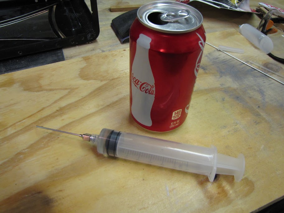
Next, I took a little scrap piece left over from the radiator housing and glued the sanded triangle to it. You can kinda see the glue seams when viewing it from the inside. To get the glue placed exactly in what was a relatively small area, I used one of these:
Terrifyingly huge, no?Worked way better than the little squeeze bottle I had before, though. The glue is so thin, it would fall right out of the needle when turned upside down, which made it impossible to control. With this plunger applicator, the suction kept the glue in place. Much cleaner!
I also made an 'extended cut' version for putting glue down into the reservoir after it was partially assembled:
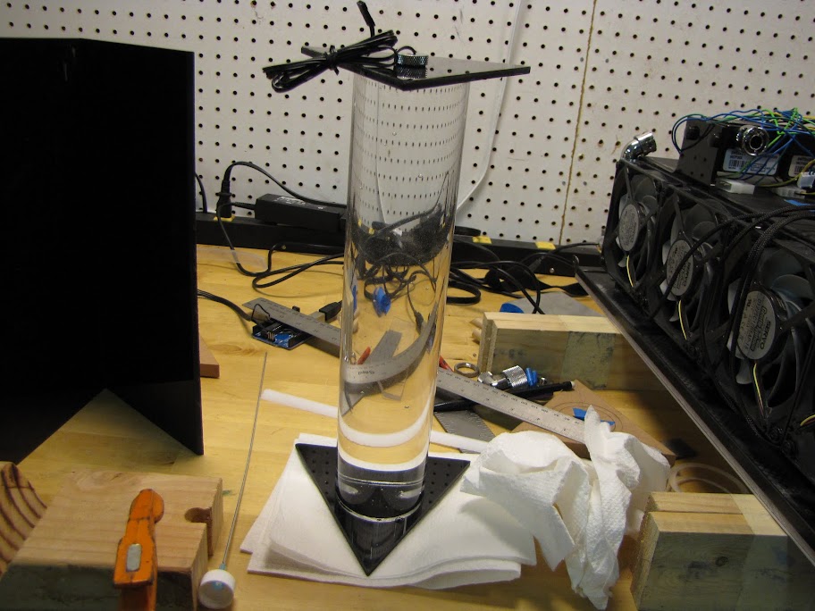
Anyway, I put the whole thing together, and used that black acrylic that I tapped in my previous post as the lid. I filled it with water, threw on a g1/4 plug, set it on some paper towels, and let it sit for a few days to see if any serious leaks developed:
After a day or so, I scoped it out and noticed only a very tiny bead of water in one of the corners. Not too bad considering the little prep work I did on this. I'd say experiment passed! Time for the real thing!
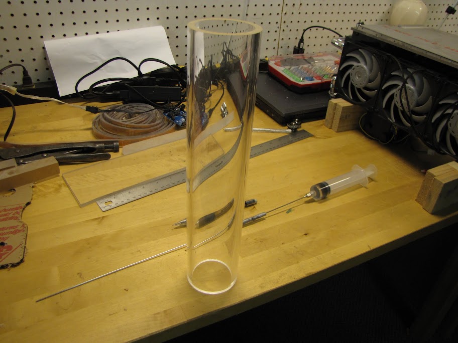
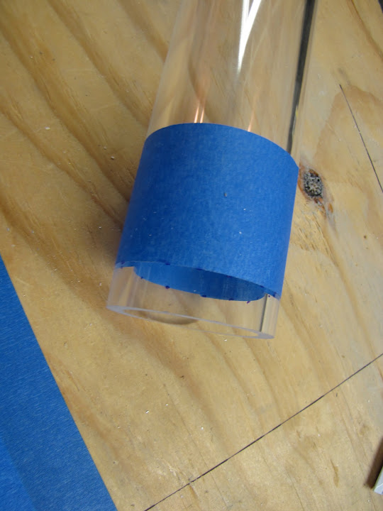
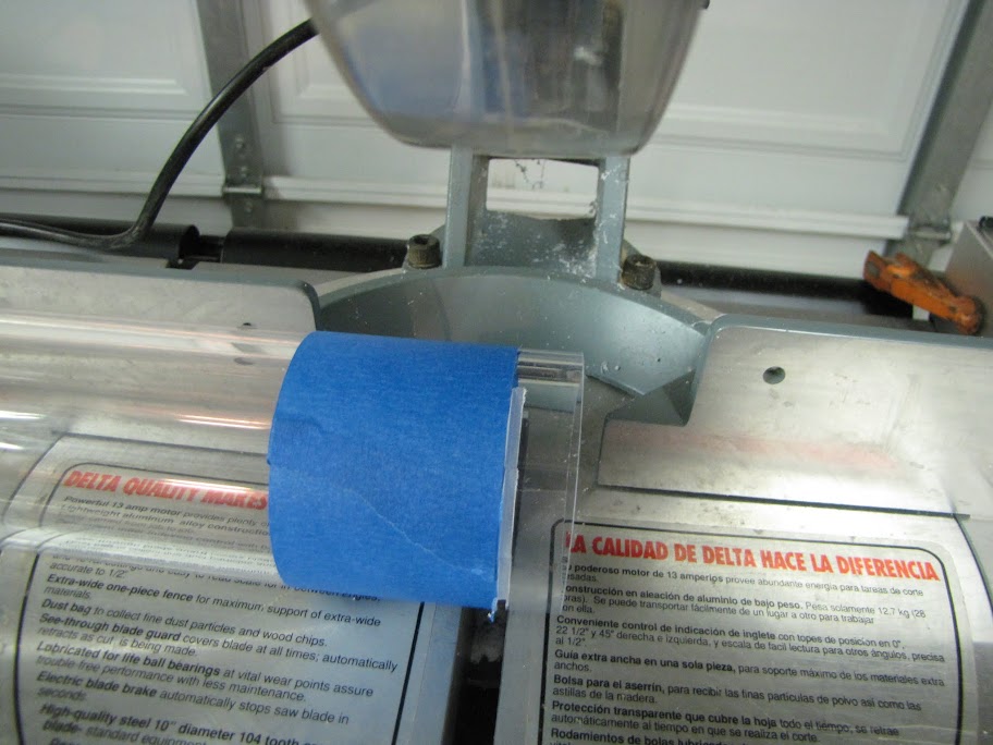
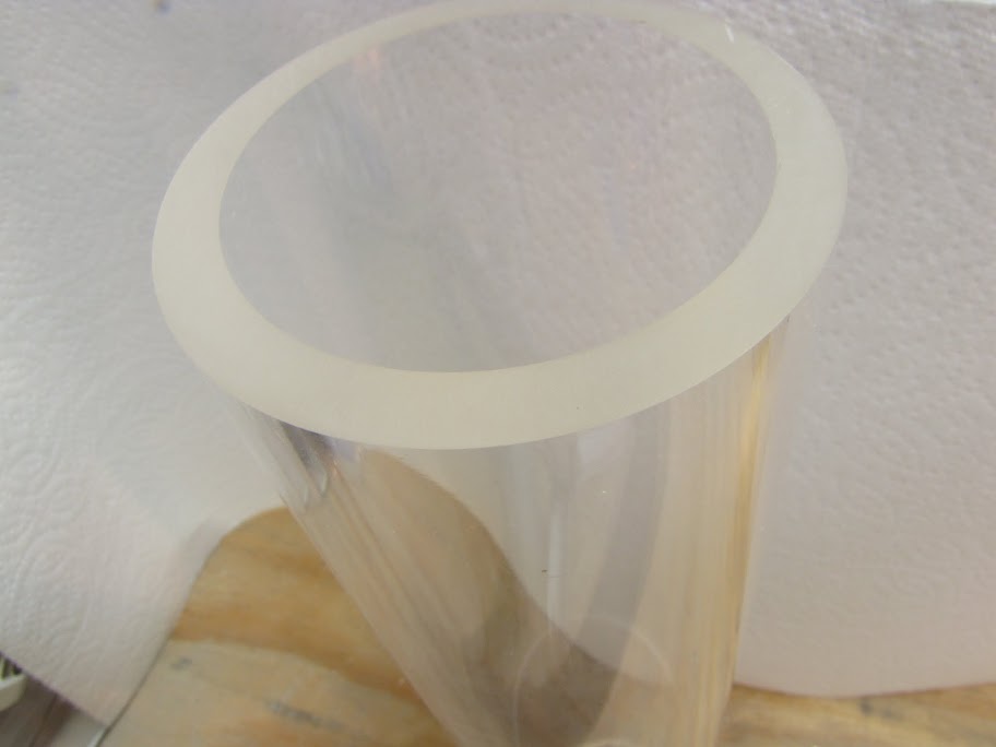
First, I had to cut my acrylic tube to the right length. I measured it all out (about six times... I was really nervous as this tube was actually fairly expensive to obtain...
Next, I broke out the miter saw with my finishing blade, and very slowly trimmed through layers of the tube at a time. I would make a 1" cut, turn the tube, make another, turn again, etc etc. Each time the cut would be a little deeper.
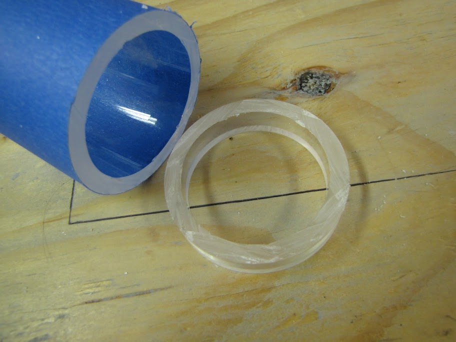
This helped make sure that I didn't heat the acrylic up so much that it melted and deformed. It also made sure the cut was that much more strait! After a few minutes of tiny cuts:
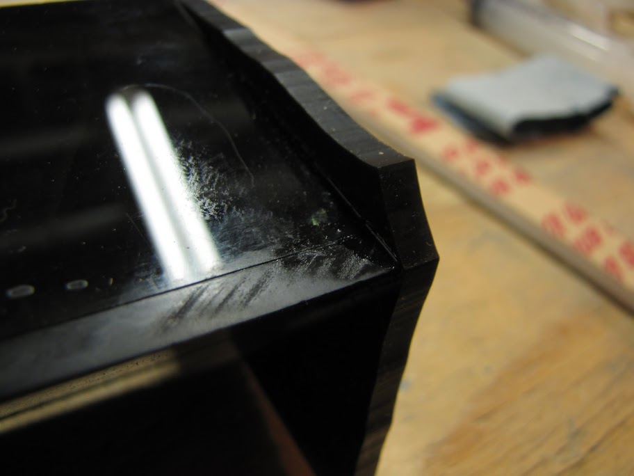
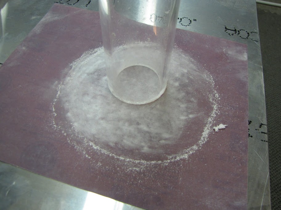
Now, I applied the same treatment with sandpaper to the bottom and top of the tube. I placed the sandpaper on a spare aluminum sheet this time, too, just to make sure the surface was perfectly flat:
Looks good!
Done with that... phew! I was nervous the whole time. It must be what it feels like to perform surgery. No room for mistakes! :p
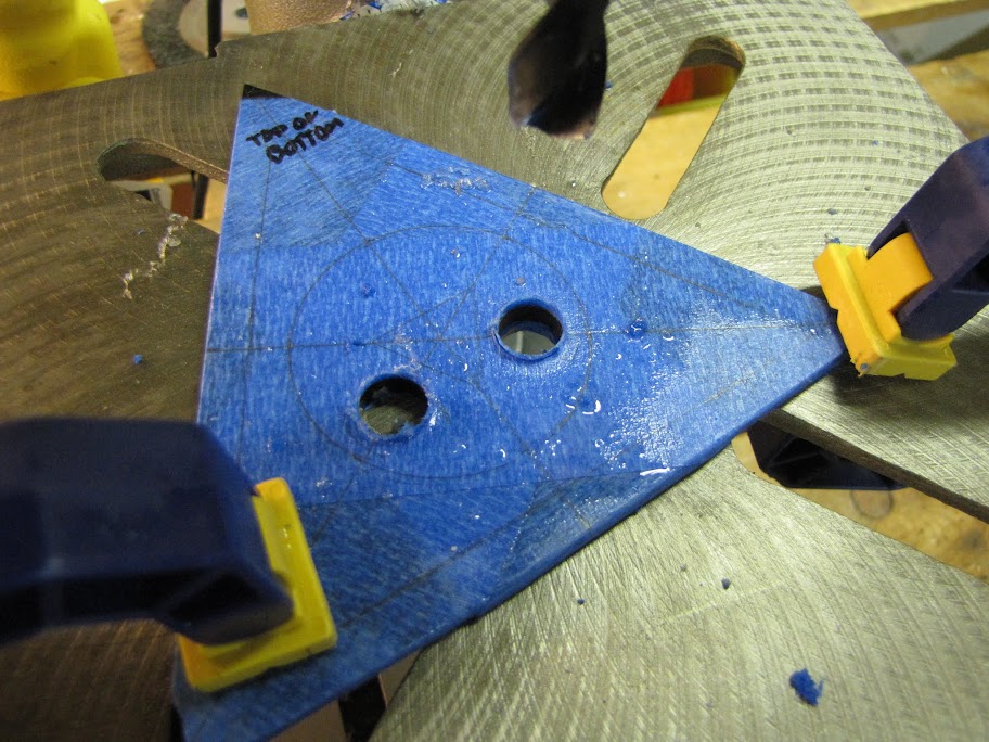
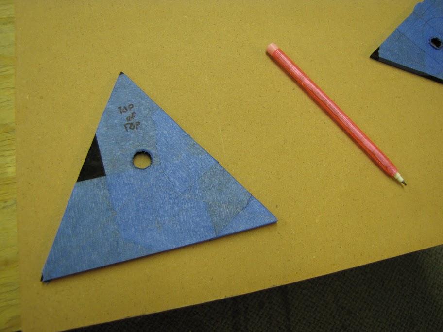
Now, I moved on to cutting and preparing the top and bottom of the reservoir. I covered the pieces in masking tape, marked up the areas with pencil, and bathed it in cutting oil to make sure I had a good clean cut:
After cutting, I tapped them using my handy tapping tool I created in my previous postings. Now I was ready to start putting the thing together when I realized... I'm obviously going to need to take the masking tape with all my measurements off before I can glue it.
Wait. I can totally make a template.
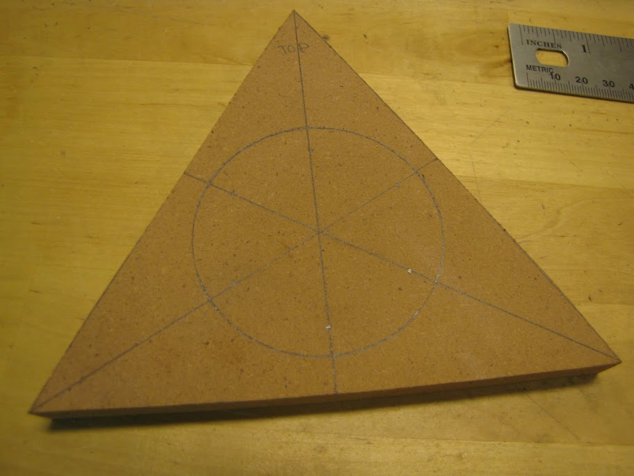
So, I broke out the MDF board I used to make my router template for my radiator housing earlier, and traced up a quick template.
A little handy work with the jigsaw and drum sander later:
Perfect fit! Now I can simply line the template up with the base triangle of acrylic, and the tube should be in exactly the right place for both the top and bottom triangles!
In my design, I thought it would be really cool to put an illuminated 'prism' of acrylic in the center of the reservoir. All I had to do was cut it out of some stock acrylic, glue it to the top and bottom just like the tube, and then drill into the ends. Simple, no? So I cut out the prism from some 1" thick clear acrylic I had left over. That's when I noticed a problem:
The prism isn't strait! But why... how?
Some research online showed an interesting property of cast acrylic that I was not aware of, called outgassing. Once exposed to air for a little while, the surfaces of the acryilc will start to vent a bit and actually shrink a tiny amount. It's not noticeable on small pieces or heavy flat pieces, but on long thin bars like this it becomes painfully apparent. That, mixed with internal stresses that are released after cutting cast acrylic, and you end up with a retarded prism.
Anyway, I figured the bend was minor enough that I could just correct it by gluing it dead-on strait to both ends of the reservoir... which would force it to 'stand up strait'. Boy was I wrong... but we'll get to that.
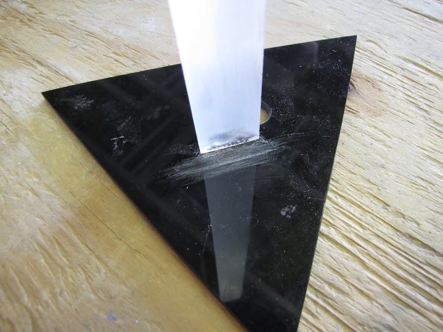
I proceeded to make a template much like the one for my tube, this time for the smaller inner prism.
I lined it up just to make sure things looked right... also to double check the process and order for gluing. Looks good so far...
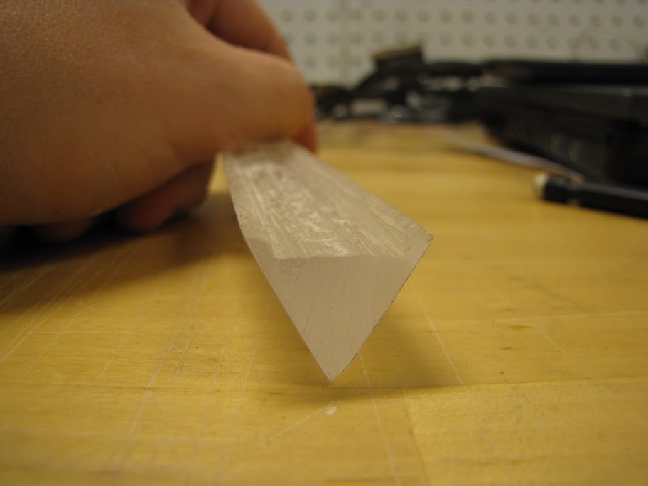
I then went on to use my flat-sanding process to prepare the prism. I ran all three sides across it for a good long while until all the imperfections were removed, giving me a nice frosted appearance which should diffuse light pretty well:
So, I clamped my template and bottom piece down and glued the prism into place. I just shot some glue where the prism needed to go (just a few drops into the center of the template), then pushed the prism in on top of it:
I thought I was good here... but the fluid dynamics I was counting on to spread the glue out evenly (capillary action) turned against me. The nearby MDF proved to be tempting enough to pull some of the glue out of the prism and under itself. I learned two things here:
1) Science never does you any favors.
2) Apparently MDF can weld to acrylic just like another piece of acrylic.
Long story short, the bottom was pretty badly marred by this. After a bit of careful scraping to remove the MDF bonded to the surface, I ended up with this:
Ouch. But all is not lost... for I now have a chance to practice my acrylic repair using all of that Novus stuff I bought a while back. It actually came out pretty well... barely noticeable now. Fortunately this is the underside of the top of the reservoir anyway, so you'll never be able to see it. It bothers me slightly, but not enough to warrant starting over!
Anyway, I went on to use my template again to glue the tube in place around the prism:
The mess on the surface next to the prism is actually just polish that I failed to clean up completely. It wasn't visible at first, but as it dried it turned white. It was a pain in the but to clean (considering it was down in the middle of a giant tube) but I managed with a dowel, some paper towels, and some patience.
Now, for another slight miscalculation, which was going to turn into a really neat feature, but which ultimately ended in complete defeat. :p
The template worked great for lining up the first piece... but now, how am I supposed to use it to line up the other side of the prism now that the tube is in the way? I obviously couldn't have lined it up first, as then I would be unable to put the tube on. I designed something that ended up being impossible to build. Go figure.
No matter! Where there is a will, there is a way, they say. And I came up with a neat idea... what if I cut out some circles that acted as a spacer between the inside of the tube and the outside of the prism? I could then put these spacers inside the reservoir at the top and bottom. This would not only ensure the prism was perfectly aligned since all the spacers would be identical, but I could use it to hide the attachment points of the prism, which weren't as perfect as I wanted. Double win, right?
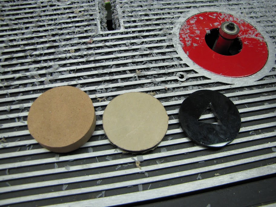
I cut out a circular template from MDF, much like the other pieces. I then used it, with my router, to make a few identical acrylic circles. I then carved out a triangle in the center which the prism would fit onto.
My plan was then to cut 5mm half circle edges off of the perimeter of the circle, so that water could flow through... but... as I was fitting the first circle onto the prism (which was glued into the reservoir if you will recall)...
Off it came!
Besides... I already had a better idea.
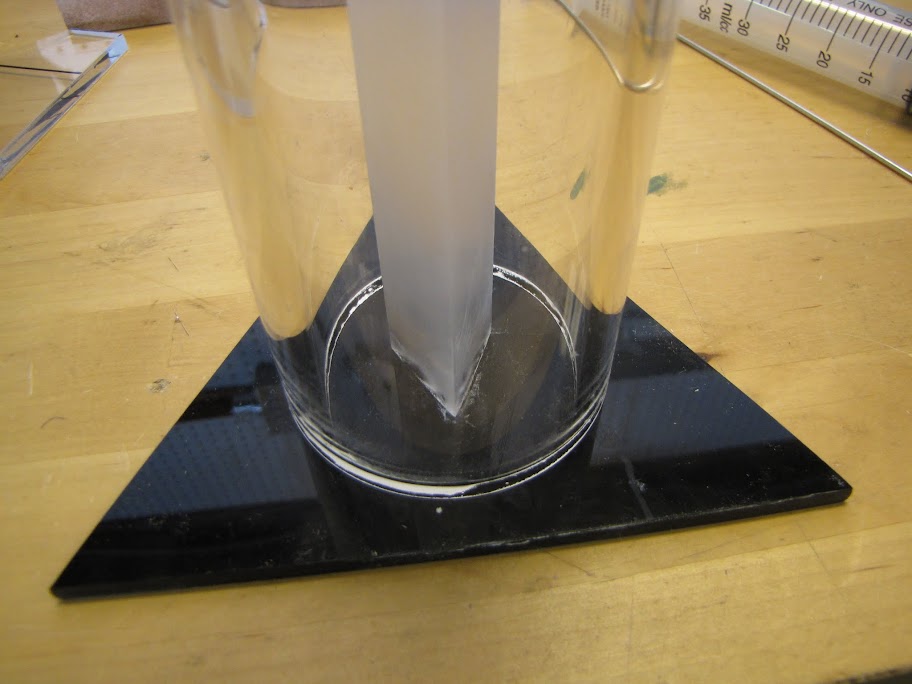
But first, I wanted to complete the reservoir "sans-prism". That was a quick task... just a shot of glue here and there... dry overnight... fill with water for testing... done!
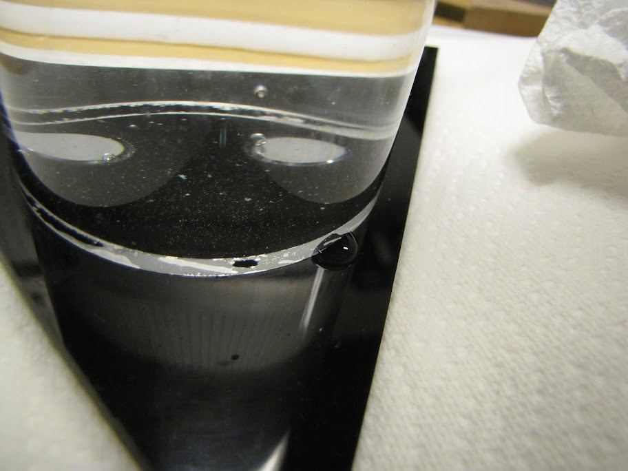
But what's this?
A tiny, stubborn leak. There's always one! No matter, I'll just drain it and give another shot of glue in that spot... that should do it!
Anyway... back to the better idea about the prism thing I mentioned earlier... I got to thinking: Why bother with putting the prism inside of the reservoir, when I could just as easily make it look like it was inside? The neat thing about bending light... is that it makes it really hard to tell what's going on behind the scenes. My ultimate goal was to fill the reservoir with light, so that it would illuminate the whole piece and allow me to display patterns and such. So... I simply laid the prism on top of the LED strip like so...
And with the reservoir in front of it...
Not good enough yet. You can clearly see dots, which isn't what I want. I tried sanding the prism a bit more, to get a coarser grain on the faces:
Hey, not half bad! It's not glued in, mind you, so it's a little off kilter right now. That, and the effect isn't quite there yet. It's too focused... too banded. I wanted a smooth effect. But how...
I played with various combinations of frosted, white, and prism shaped pieces of acrylic to try and achieve the effect. Here's one with a translucent piece of white acrylic that is supposed to be good at dispersing light. Getting closer... but now it's pretty dim. The acrylic almost blocks too much light.
After monkeying around, I got pretty close to what I wanted as far as appearance goes (again, it's not strait since the housing is in the way of the prism right now):
Almost a solid column of light! But... it takes quite a bit of material, and I'm not even sure it will fit in there correctly. I achieved this effect by putting the LED strip behind a 1" thick block of acrylic, and then putting a very thin strip of the diffusing acrylic on top, like so:
With this profile view, you can see why... see those angled beams of light coming out of each LED node? The dispersing white acrylic is far enough away from them (due to the 1" acrylic buffer) that those cones of light overlap. Now I just need to find a way to better disperse that light without requiring a full 1" gap.
So today, I went and picked up a few more different shapes of acrylic... hopefully they arrive soon, so I can keep testing! I can feel the answer is close... I'm excited! xD
Until next time!
EVGA z77 FTW -- 16GB of Samsung MV-3V4G3D/US -- Intel Core i7-3770k -- EVGA GTX680 -- Corsair AX850 PSU -- Lian-Li PC-v2000b -- 2x XSPC RX480 Rads -- EK-RES-250 -- EK-DDC Dual Top/pumps -- EK-FC680EN Full Cover block -- Swiftech Apogee HD Block
Hello!
Small update this time... well... small in content, but not small in effort nor small in 'size'!
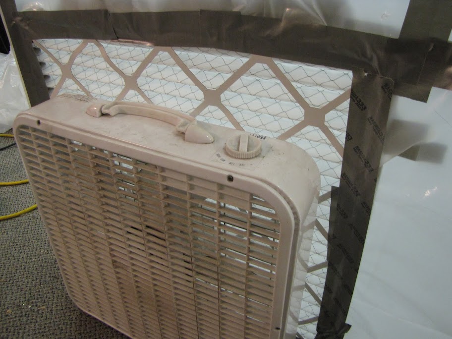
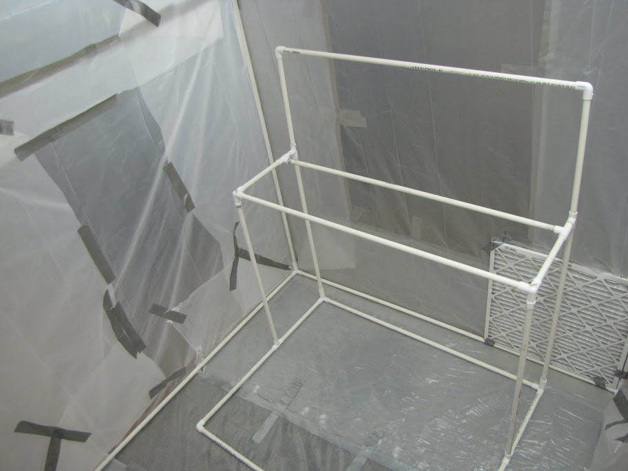
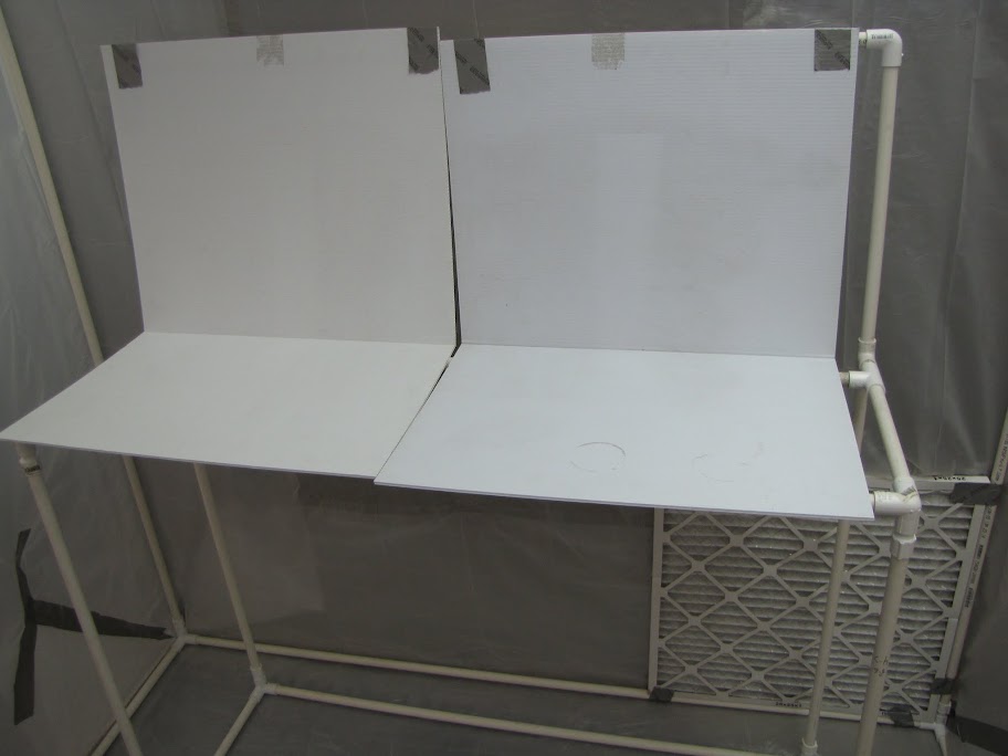
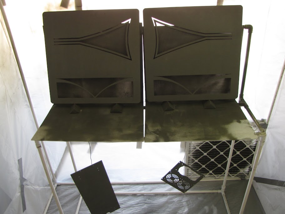
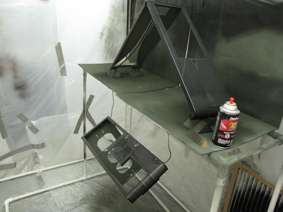
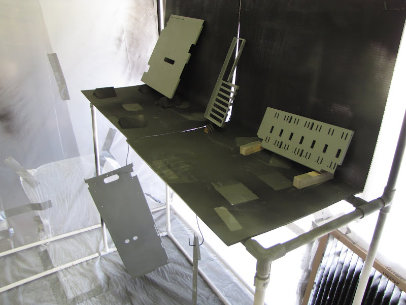
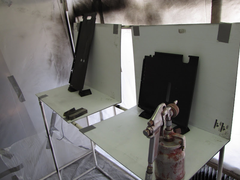
I only had bits and pieces of time due to a hefty workload with my day job... but I managed to put together my painting booth finally! It looks like something 'Dexter' would put together... :p
Now I don't have to worry about getting paint (or blood...) everywhere, and hopefully all that dust/hair/bug nonsense won't mess up my finish!
I also added some cutouts for ventilation, with air filters, so that I get some fresh air in there and cut down on the dust at the same time.
Inside, I have a simple 'bench' that I can hang pieces from, or set up as a shelf for small parts:
Anyway, now I just need some time to prepare all my parts and I can get to painting!
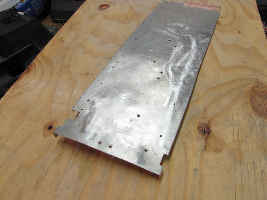
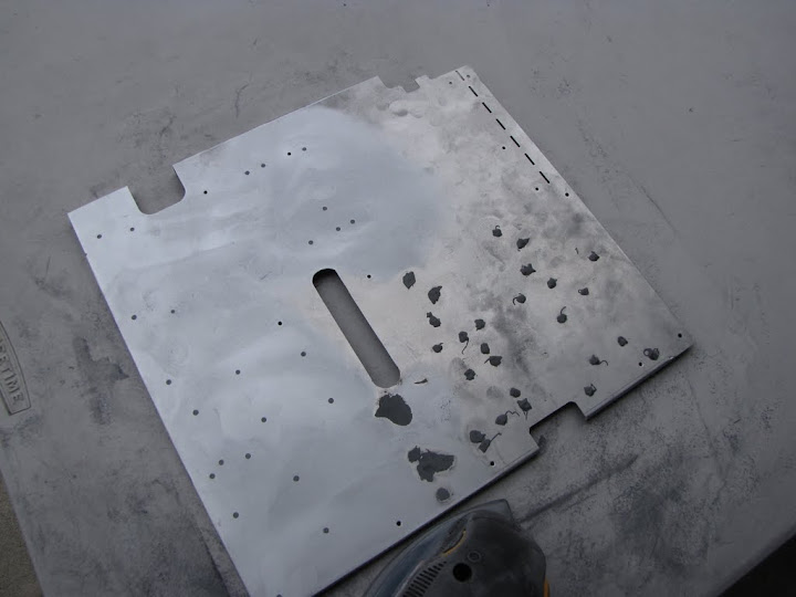
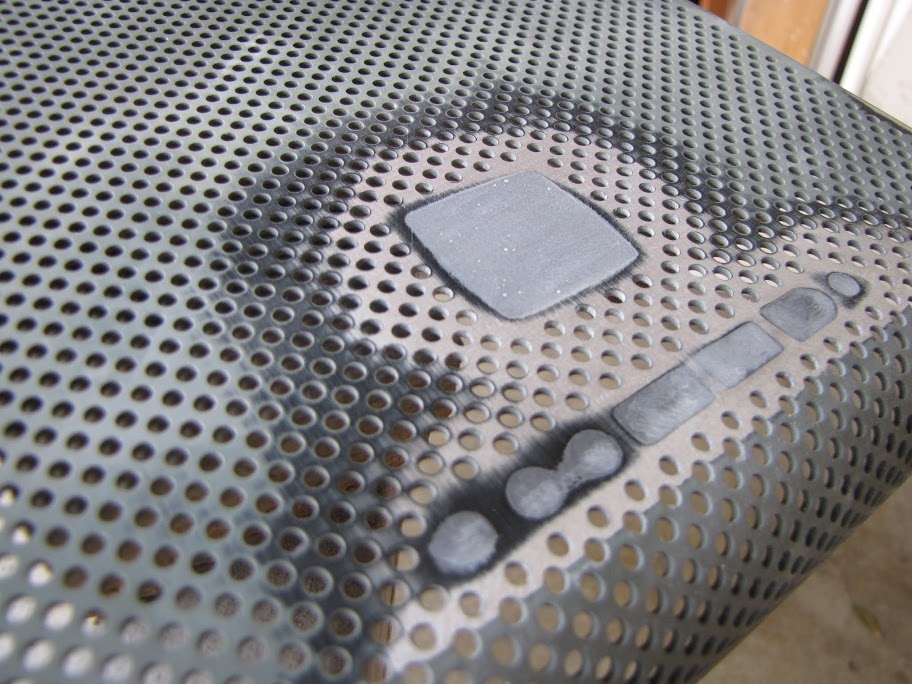
Also, I finally got my midplate back from the welding shop...
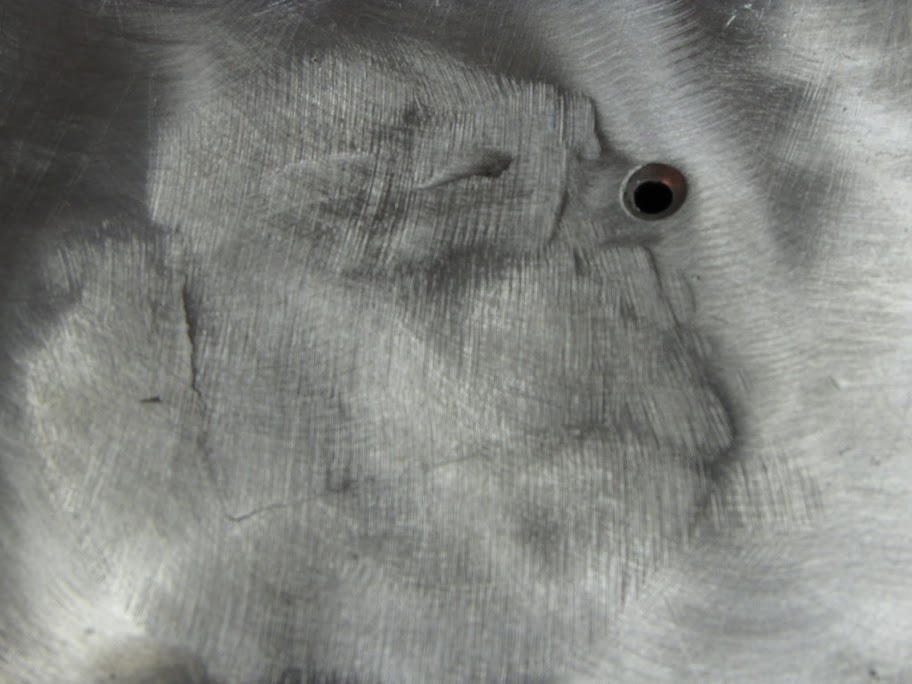
At first glance, it looks pretty good. The top was ground down pretty flat. The underside has some large ugly welds, but I think I can clean up those with a little elbow grease:
However... I started to notice a pretty significant problem:
The piece is warped. BAD.
I'm worried I won't be able to use this piece after all. It was expensive to have welded too... and I was too much of a nice guy to not pay them, since they are a small shop.
So... with nothing left to lose, I decided I would do what I could to try and 'flatten' it:
I didn't have a lot of luck with the rubber mallet. After beating the heck out of it for about a half hour, I had only made very minor progress. It was pretty evident this would never get the job done.
I also tried 'crushing' the bent areas in a vise:
That worked a little better. At this point the piece is 'relatively' flat. I'm still thinking I am going to have to recreate the piece from scratch... but I'm going to go with it for now until it proves too warped to use. If I can see that it is warped after assembling the case, I'll redo it. No compromise, eh?
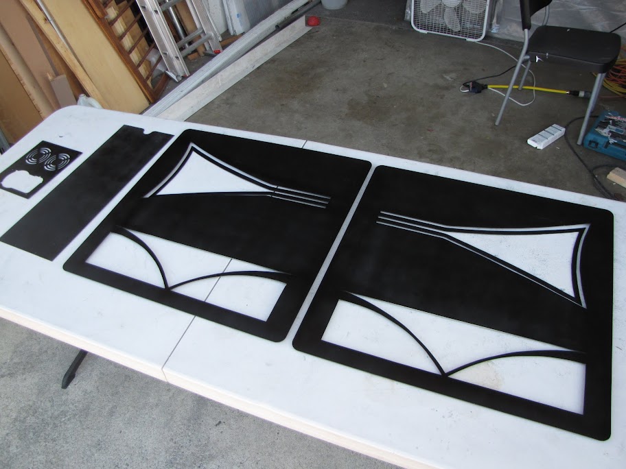
Speaking of reassembling the case, I wanted to put everything that has been made together briefly, just so I could get a feel for how things are looking. I quickly put it together using some painters tape just to hold pieces in the right places:
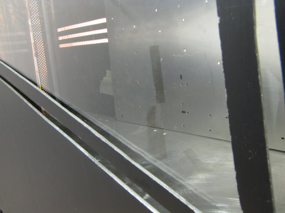
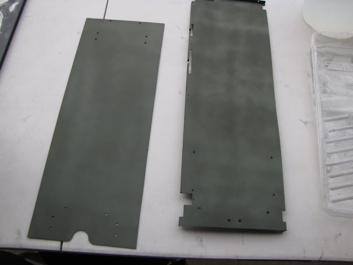
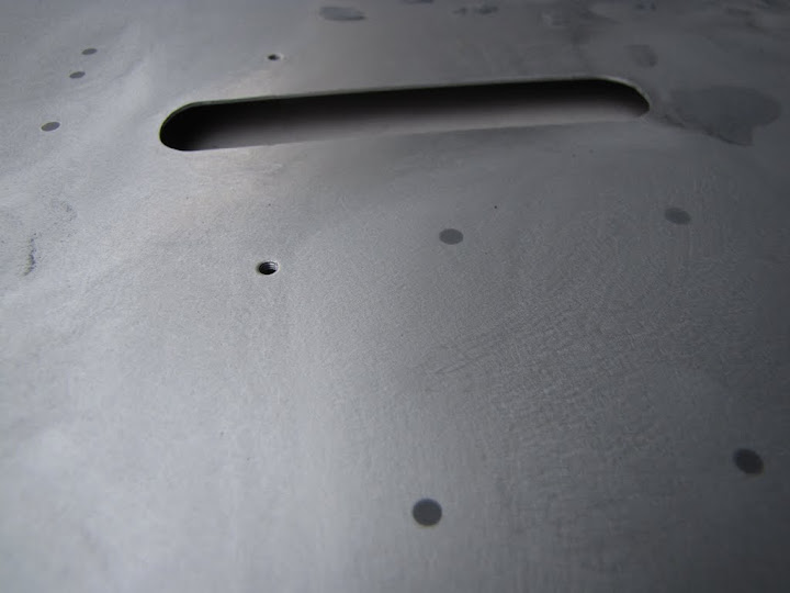
Considering the relatively small window size, you don't actually get a very good look at the mid-plate... even when looking right in the window:
Here's a shot from the "IO shield" area... also not too bad looking.
Can't really tell that it is only slightly warped at all. I'll go with it... for now...
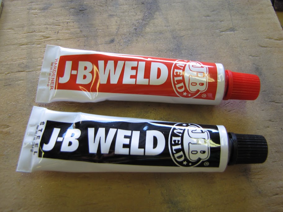
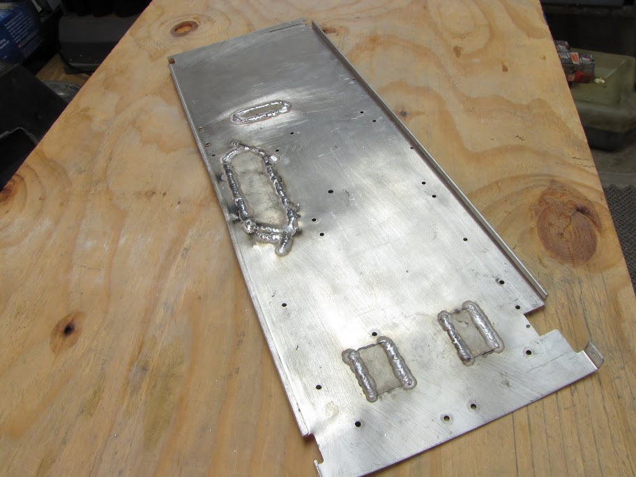
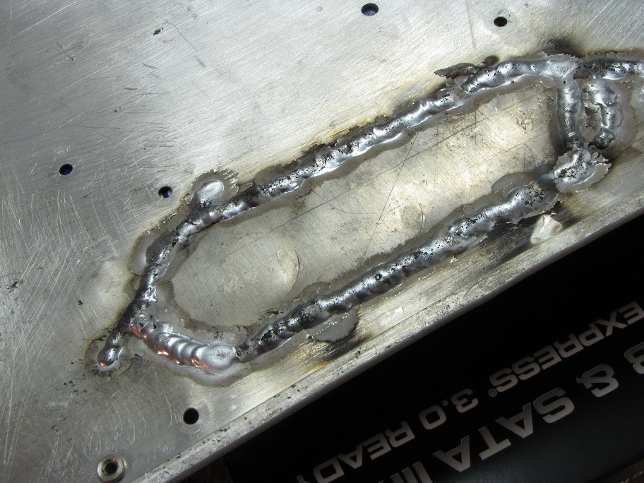
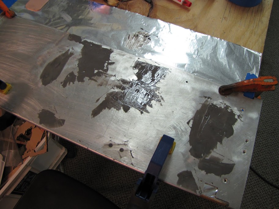
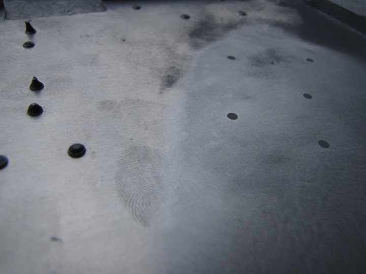
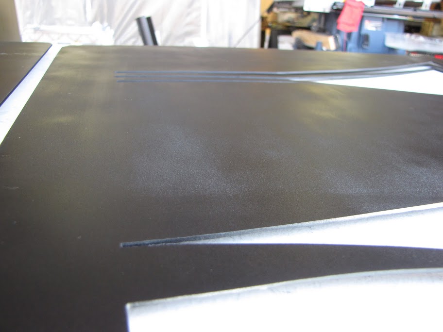
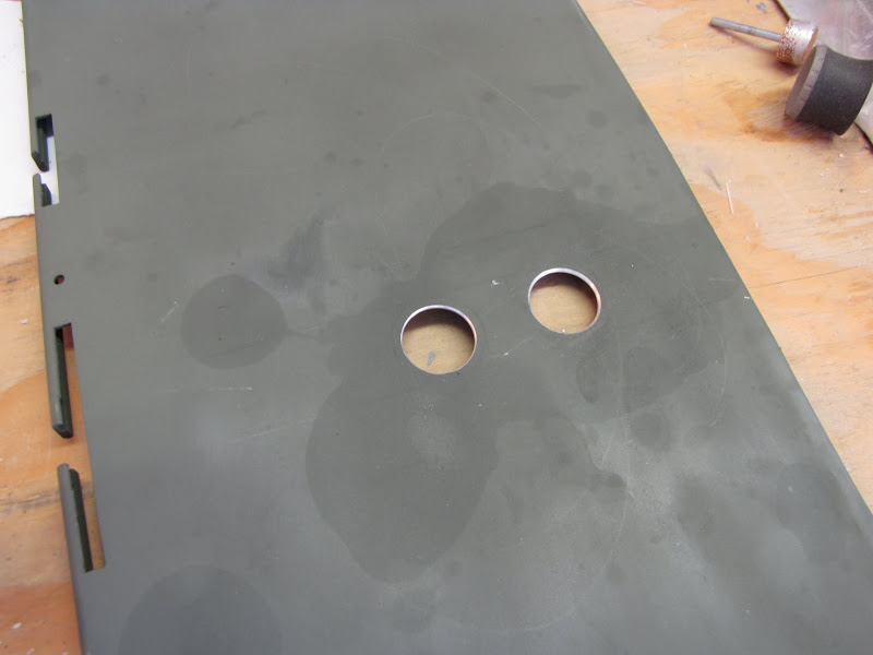
So, I set to work cleaning up some of the smaller imperfections. There are many rivet holes in the piece that will no longer be used as a result of the modifications I made to the case (such as removing the hard drive cages) which I needed to fill. To fill it, I'm using some JB Weld, which hopefully will work much better than the Bondo. After the first coat...
And then a second coat to smooth out the remaining dimples:
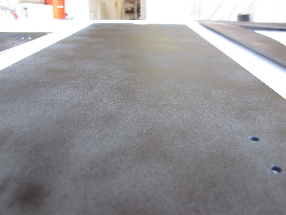
I'll likely do one more coat tonight on the underside if necessary, then sand it flat for painting.
Anyway, I hope to have a bunch of free time this weekend as the wife is working all Saturday and Sunday... leaving me with nothing to do... but paint!
EVGA z77 FTW -- 16GB of Samsung MV-3V4G3D/US -- Intel Core i7-3770k -- EVGA GTX680 -- Corsair AX850 PSU -- Lian-Li PC-v2000b -- 2x XSPC RX480 Rads -- EK-RES-250 -- EK-DDC Dual Top/pumps -- EK-FC680EN Full Cover block -- Swiftech Apogee HD Block
So... I didn't do nearly as much this weekend as I wanted to.
First of all, I continued work on the reservoir a bit. I received some various bits and pieces of acrylic to try different shapes and sizes and see what I could do to diffuse light better. Unfortunately, none had the effect I was looking for. I tried rods, half-rods, spheres, semi-spheres, cutting long grooves into the back side of the prism... not much seemed to make a difference in how diffused the light was. Here are some experiments I did, with descriptions of what you are looking at attached to each video:
Test 1
Test 2
Test 3
Test 4
I did many other tests, but most of them proved to be a detriment (they actually focused the beam, or scattered the light into a rainbow) rather than help. I think when it comes down to it, the LED lights on my strip are too far apart, and the acrylic I am trying to light is too thin, to accomplish the look I want. Naturally, I started poking around online for a solution... and come to find the same company that manufactured my current LED strip made a Version 2 recently that is double density! I snapped up a couple of meters, and we'll see how it looks!
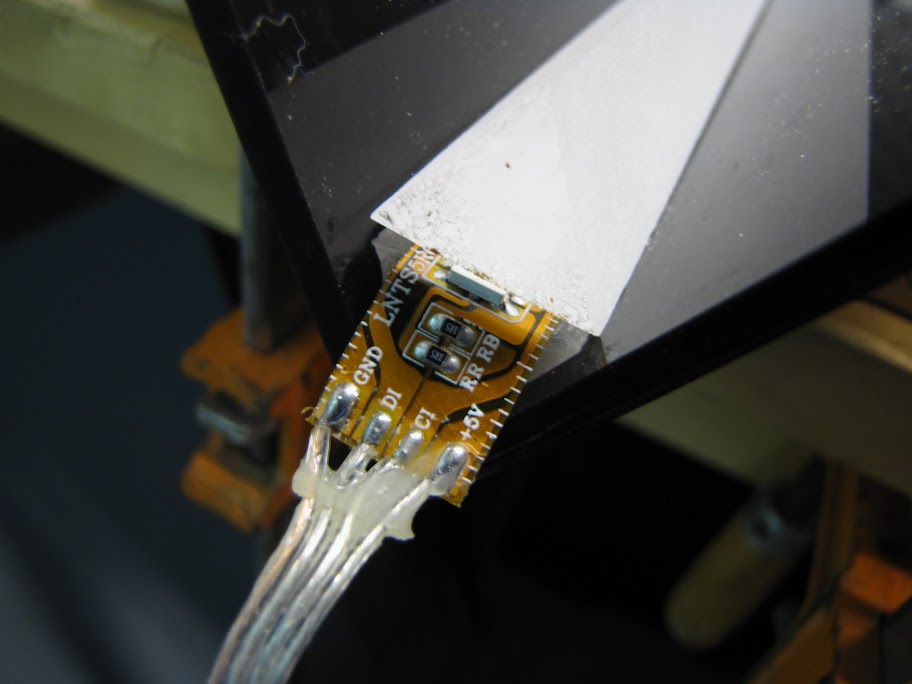
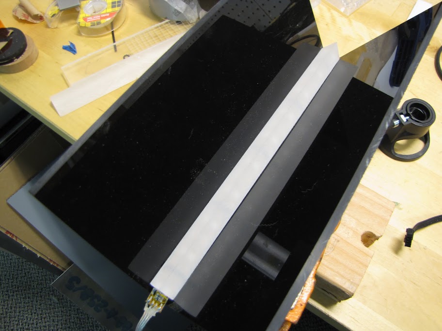
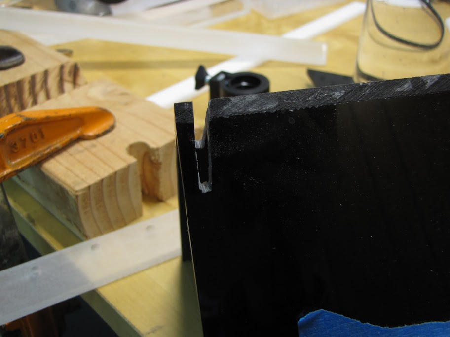
Anyway, in the meantime, since I still needed something to do this weekend, I went ahead and prepared the prism housing with the anticipation that the double-density strips will absolve the problems with light distribution I am having. First, I cut a channel into the bottom of one of my prisms approximately the width and depth of the LED strip:
Next, I laid the strip in the channel to make sure it fit. There is a slight overlap at either end with this kind of strip that I am hoping I won't have with version 2, but there's a distinct possibility it will. Also, there are contacts at either end of the strip that I will likely want to wire up so that I can chain this on to another location instead of running another lead from my Arduino... so I need some way to reach those contacts. I trimmed the prism with the channel slightly, so that when the top prism sits on top of it, there is a slight gap on either side, like so:
When laid into the housing, it still overhangs slightly, and there's still the matter of what to do with the wiring. When I glue the tube reservoir into the housing, the bottom area shown here will be completely sealed and set against the bottom of the midplate.
A simple solution came to mind... cut a port in the back of the housing like so:
Now, I can glue the bottom in place and the wires won't be in the way. Additionally, this port will be completely invisible as the prism will be covering it from the front, and I'll have 'other stuff' obscuring the back of the housing (more on that much later...
Just for the heck of it, I lit up the current light strip with the unit all built. It's not glued together yet, since I will be replacing the Version 1 strip with a new Version 2 soon... but I couldn't let all of my work go without immediate reward!
Also, a brief video, so that I can compare it to what version 2 will look like when I get it!
Anyway, enough of that for now... on to something else! I did a little shopping at the local hardware store in preparation for painting, even though it wasn't shaping up like I would be able to paint this weekend:
I also started figuring out what I wanted to do with cable routing from my power supply. As you can see from this shot, my space is very limited in this case:
I'll need to make cuts in the midplate somewhere in order to pass the ATX cables from below the midplate up to the motherboard and peripherals... but I'd like to do it in a very 'stealthy' way. Also... there's the little matter of ventilation for the power supply. There's only a few millimeters above and below the power supply. In the current installed configuration, the fan is butting up against the midplate. I'm not sure if that's enough room for ventilation... but then again, this power supply only activates its fan when it is hot... and it's rarely on if ever... so...
I played with the idea of cutting a hole in the midplate about like so:
I don't think I like it though... so I am tempted just to see how it goes with limited ventilation.
I also played the location for CPU power cables to come up through the midplate... and I think what I will actually do is cut out a section of the motherboard tray and feed the cables under the motherboard. It's a little hard to explain, but here's where I am thinking of routing the cables (I just stuck a spare cable I had under there to make sure it fit, and to illustrate my idea. The final cables will obviously be sleeved:
To fit the cable there, I'll cut a section out of the back side of the midplate, as well as a bit of the motherboard tray just above the markings shown here:
I plan on doing something similar with the ATX power, and the PCI-E power cables too. I'll cut a similar section like above, route the cables along the back of the motherboard tray, through an opening that will be hidden behind the motherboard, out from under the motherboard, and into the power ports. Clear as mud? :p
Anyway, next time I'll keep going with the cable routing preparation. I also hope to get the new LED strips this week. See you next time!
EVGA z77 FTW -- 16GB of Samsung MV-3V4G3D/US -- Intel Core i7-3770k -- EVGA GTX680 -- Corsair AX850 PSU -- Lian-Li PC-v2000b -- 2x XSPC RX480 Rads -- EK-RES-250 -- EK-DDC Dual Top/pumps -- EK-FC680EN Full Cover block -- Swiftech Apogee HD Block
Hello!
Been a little while since a full update, but I've certainly been busy! Lots of little things here and there, but bit by bit I'm getting closer to putting everything together!
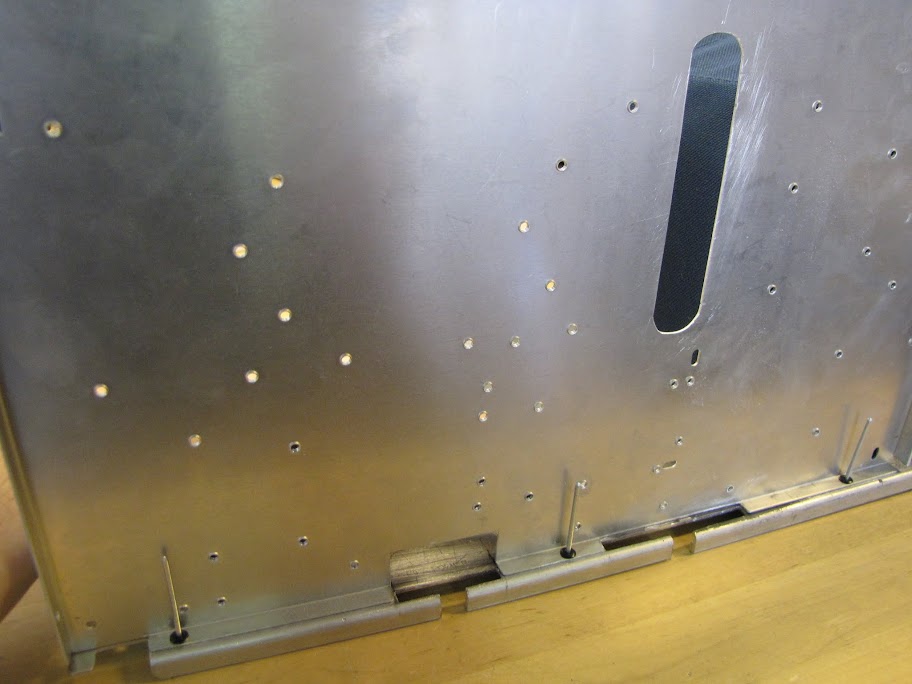
First, I worked out how I want to handle my cable routing. You'll recall that I pluged all the cable pass-throughs on my midplate, leaving no place for cables to reach the motherboard... One of my personal goals is to keep the cabling completely hidden wherever possible. This includes fan wires, motherboard power, sata cables, etc etc. To do so with the Lian Li PC-v2000 is a tricky thing... this case was made back before case windows were a big thing... and people didn't care about cable placement. None of those fancy cable management systems here... so, time to make some!
There's a very small gap behind my motherboard plate and the left hand case wall... no more than 10mm. That should be enough to accomplish what I am thinking, though! I marked off a few areas that I'll be passing cables from the bottom compartment (you can see the PSU there) along the back of the motherboard plate and up to the top compartment. An hour or two with the Dremel, a little bit of sanding, and...
... there we go! Cable pass through ports along with built in cable retention arms!
Next, I cut out a few matching holes in the motherboard tray, along with a few passthrough ports that will be hidden behind the motherboard when it's mounted on the tray:
Put the two together, and...
There we go! Now, when the motherboard is mounted on the tray, these passthrough ports will be completely invisible.
The back area will be hidden as well, as this area is out of sight of the window on this side of the case. I'll route the CPU power cables and fan RPM monitor cables up through the left port, which will come out underneath the bottom of the motherboard. The cables will make a sharp u-turn and plug into the motherboard. With some careful cable stitching and placement, it should end up looking very clean. The ATX power and GPU power cables will go through the right port, be tacked flat along the back of the motherboard plate, pass through the large oval, come out under the motherboard, make a sharp U-turn and plug into the motherboard power ports etc (which are conveniently turned 90 degrees on the EVGA z77 FTW motherboard).
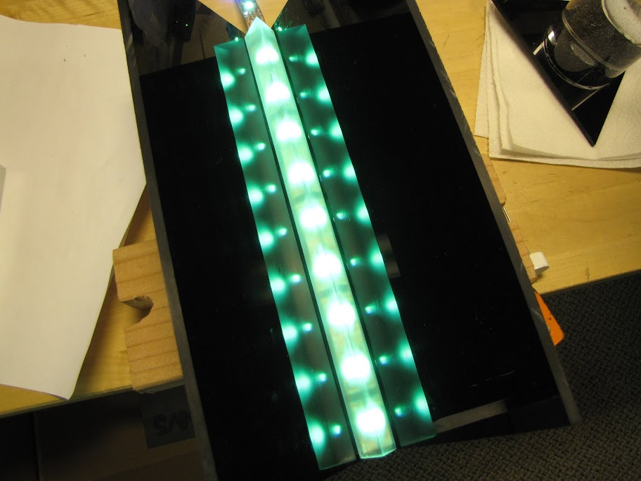
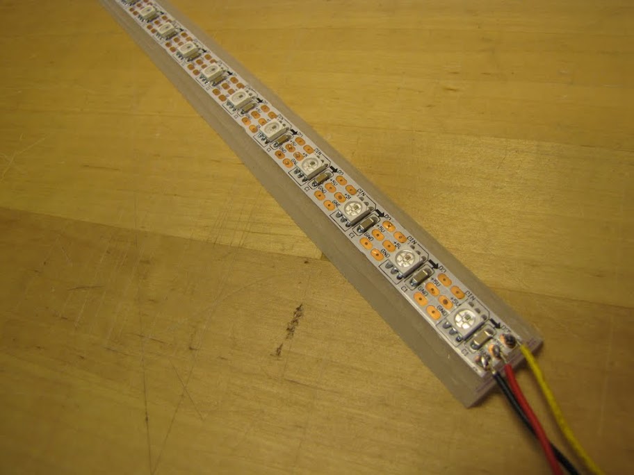
Anyway, back to something more... colorful! :p I picked up some higher-density LED strips from the same manufacturer as my old strip, Adafruit. Lots of good improvements here... no black CPU chip (it's actually that microscopic black dot on each LED now!), the strip is a much more unobtrusive white instead of copper, and of course there are now 60 LED's per meter instead of 32.
As such, I pretty much started over at square one with all of my LED/Acrylic testing. Here's a few shots of various layouts I tried. All of them still show banding or individual LED's, which I am trying to avoid... the goal is a smooth transition of color where the individual lights are indistinguishable.
Trial 1, with the LED facing up into the prism:
Trial 2, with a sanded groove and extra piece of acrylic between the LED strip and the prism:
A little closer on that second one, but not quite there.
Trial 3, LED strip upside down, facing into a second prism underneath the top one (so an acrylic diamond with the LED strip in the middle):
The light is much better in this one... almost perfect, but as you can see in these dark shots, the LED strip is visible through the prism as a black bar... which kinda ruins the effect.
Trial 4, I also tried putting the LED strip sideways shining into the bottom of the acrylic 'diamond', hoping that the light would reflect a bit and hide the source... but you can still faintly make out the individual lights:
Putting other materials, hot glue, paper, and other materials also had no effect on dispersing the light any better:
So, I slept on it a bit. The problem I was having was that the light coming out of the LED's was still to focused... they formed small cones of light that hadn't completely merged by the time they exited the prism, no matter which way I faced them. What I needed was for the light to travel a greater distance, allowing it to scatter more. The downward facing strip worked pretty close, but it was a bit too dim and you could see the strip. What combination of materials and shapes will increase the travel distance of the light, face the strip downward, AND keep the strip hidden? Smoke and mirrors! Or more specifically, cloudy acrylic and mirrors!
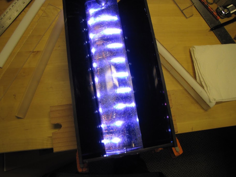
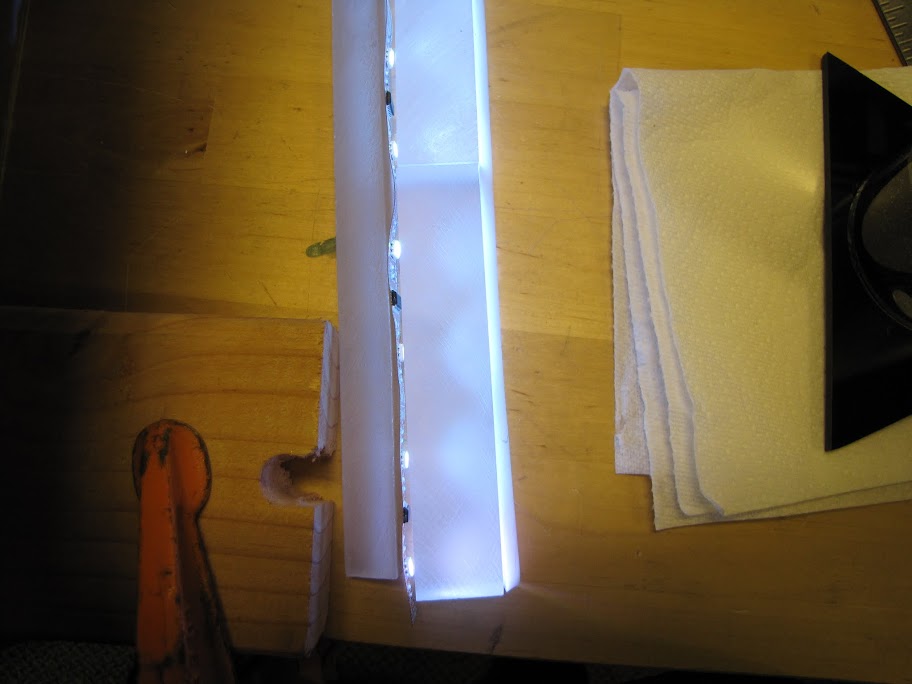
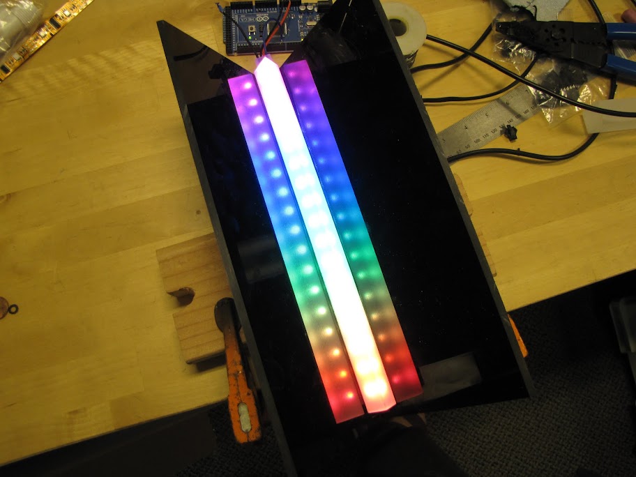
First, I made a "V" shape out of some 2mm clear mirrored acrylic. This will act as a 'basin' to face the LED strip into, reflecting all of that light back up. I glued that V into the bottom of my reservoir housing:
I then glued the LED strip to a trapezoid of acrylic that I passed through my drum sander a few times, clouding up all the edges to obscure the LED strip.
I glued the LED strip face down into the mirrored V...
Powered it up, and voila!
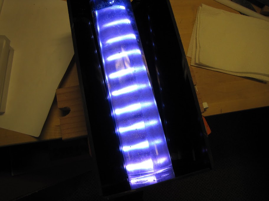
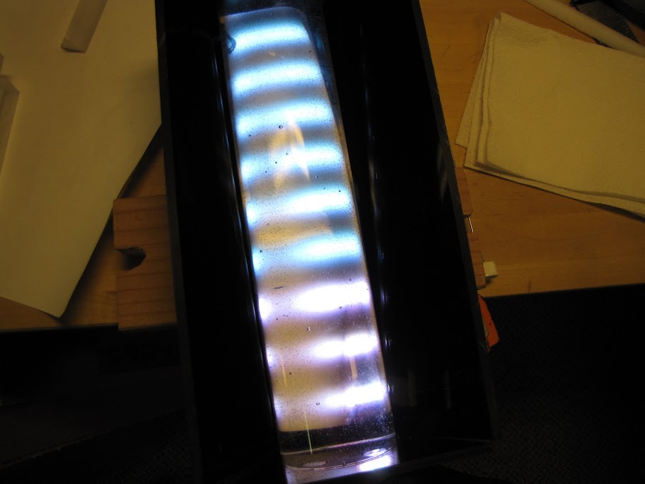
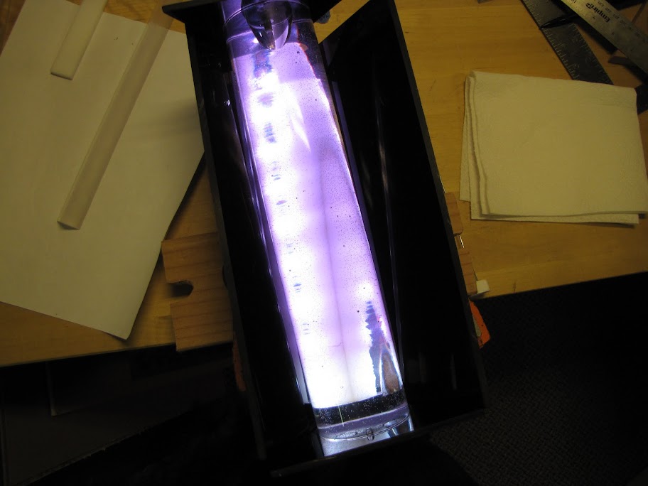
And with the lights off and the tube reservoir in place (albeit empty...)
Perfect!
Sooo good to have this piece finally done. It's been bothering me forever! Now on to the next task... finishing up some of the repairs on my mid-plate. Until next time!
EVGA z77 FTW -- 16GB of Samsung MV-3V4G3D/US -- Intel Core i7-3770k -- EVGA GTX680 -- Corsair AX850 PSU -- Lian-Li PC-v2000b -- 2x XSPC RX480 Rads -- EK-RES-250 -- EK-DDC Dual Top/pumps -- EK-FC680EN Full Cover block -- Swiftech Apogee HD Block
Hello!
The dogs agree!
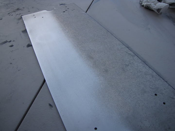
First, I prepared some of my parts with wet sanding to get rid of all the oxidization, giving a nice clean surface for the primer to bond to. Some pieces were worse off than others... my bottom plate was made out of scrap aluminum that seems like it had been sitting in the desert for a few years... but after a bit of elbow grease (and P400 wet sandpaper) it was looking good as new (you can see the cleaned half on the left, the unclean on the right):
I also continued preparation on my mid-plate. If you'll recall, I set about to clean up some of the welding spots on the bottom. I tried grinding it down with a Dremel stone, but that proved only to coat my stone in aluminum... not so much grinding action happened there. :p I then went and picked up some Bondo body repair aluminum bonding filler. That stuff was scary! The warnings and such on the side basically said to go to the hospital no matter what. Touches your skin? Go to the hospital. Breathe it in? Hospital trip.
I'll spare you the in-depth process I went through after that to get it ready for painting... trust me, it took forever and was not very exciting/pretty to look at. Instead, I'll summarize: After letting that stuff dry for a few days, I went at it with my new mouse sander and ground it smooth. After that, I used some regular bondo to fill in the smaller crevices and such, and sanded it once more. After that, I wet-sanded it to get a nice smooth surface using some P400, washed it off with some water, washed it again with some denatured alcohol to remove any oil, and I was finally ready to primer it!
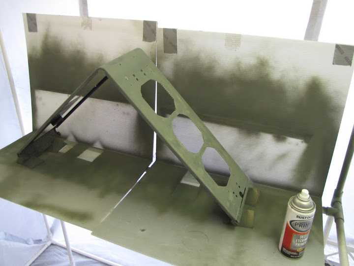
Here you can see it all propped up on some quick 'painting feet' I cut out of a spare 2x4, sitting in my painting booth, ready to roll. The results after the first coat, just lightly dusting horizontally, making sure to continue spraying all the way off the edge before stopping:
Two minutes later, the second coat, same process but vertical passes this time:
And finally the third coat, all primed up. I let this one dry for about 30 minutes before taking it out to wet sand it:
I wet sanded with P1500 using a sanding block, tap water, and just a dab of dish soap to break any surface tension in the water. I'd say I made about 10 passes over every location, letting the block glide and not pushing down hardly at all... enough to get rid of some of the overspray and 'noise' but not so much as to clear primer off back to the base layer. Now they're hanging in my super expensive drying rack in my garage. Also known as a nail with a piece of coat hanger wrapped around it.
In the meantime, I followed the procedure with other pieces:
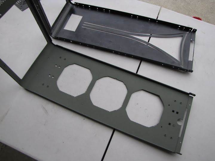
Here's the bottom half of the case all primed and ready. For comparison you can see the top half next to it that is about to be primed as well:
I actually managed to get everything all primed and wet sanded in one day! It was a lot of slow deliberate work... 7 pieces in all, coated three times, wet sanded and curing. It took about 4 cans of primer, which I don't think was too bad considering how much surface area I had to cover. :p
While those pieces were on the rack drying, I moved on to some other preparation work. I filled all of the extra holes in my motherboard tray with some bondo, then sanded it down using the mouse sander. This way, when painted, it should be nice and clean. I know no one will be able to see most of it... but I'll know it's there.
I also set about to sand down the backside of the motherboard tray. While the hole fillings were drying, the bondo actually formed small stalactites (or are they stalagmites?
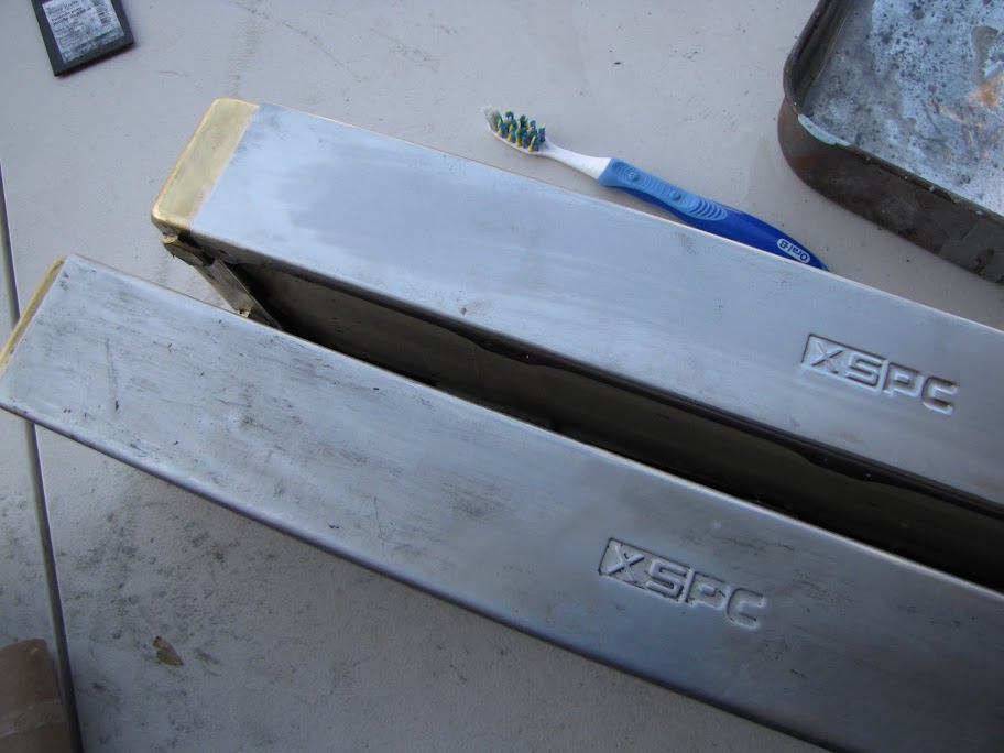
I wet-sanded and cleaned this piece, and primed it as well. After that, I did one last thing with my day, and that was to take apart my radiator core and prepare the radiators for painting!
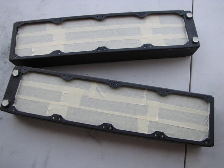
I carefully put masking tape on the fins to protect them from damage and paint, and I also cut out some covers for the threads to keep any debris from getting inside the radiators. You may have seen in some of the other photos, but the paint on these was really cheap, or really poorly done... it scraped and chipped off with barely any effort. I figured it would be a piece of cake to remove it if that were the case, no? I could not be more wrong.
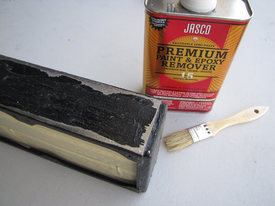
The picture below is after an hour or two of effort. The left one was sanded down using my mouse sander and about 3 P120 grit sanding pads (which aren't cheap, by the way!). The one on the right was done using some mineral spirits and a scraping knife. Both took a ton of effort and are nowhere near done. I have a feeling I went about this all wrong... so I went down to the local hardware store and picked up some paint remover meant specifically for aluminum, along with some brushes and scrapers. I haven't tackled this again yet, but I have a feeling it will work much better this time...
Anyway, that's all for now! I'm still in the midst of painting and such, and will post some pictures when I get something presentable! See you then!
Last edited by Noblesoft; 03-30-2013 at 09:50 PM.
EVGA z77 FTW -- 16GB of Samsung MV-3V4G3D/US -- Intel Core i7-3770k -- EVGA GTX680 -- Corsair AX850 PSU -- Lian-Li PC-v2000b -- 2x XSPC RX480 Rads -- EK-RES-250 -- EK-DDC Dual Top/pumps -- EK-FC680EN Full Cover block -- Swiftech Apogee HD Block
![Send a message via AIM to [XC] moddolicous](images/misc/im_aim.gif)
Awesome project log! I'm really interested in the Arduino coding / timing LED stuff. Either way, keep up the awesome work!
Hello!
Painting... takes a long time! At least the way I'm doing it (which is very obsessive compulsive...)
Anyway, I thought I should update on my progress since it's been a while, even if I'm not done yet. I've been doing quite a bit these past few weekends, but due to the nature of the painting process I'm developing, work is rather slow and has to be spread out over several days. Fortunately, I had lots of other little side projects that I could fit in between coats of paint and such.
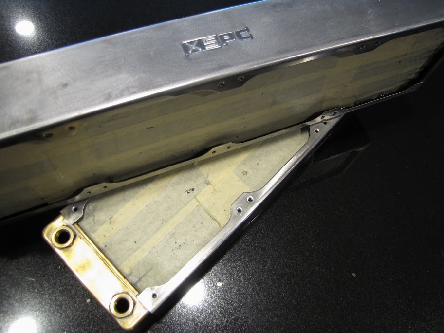
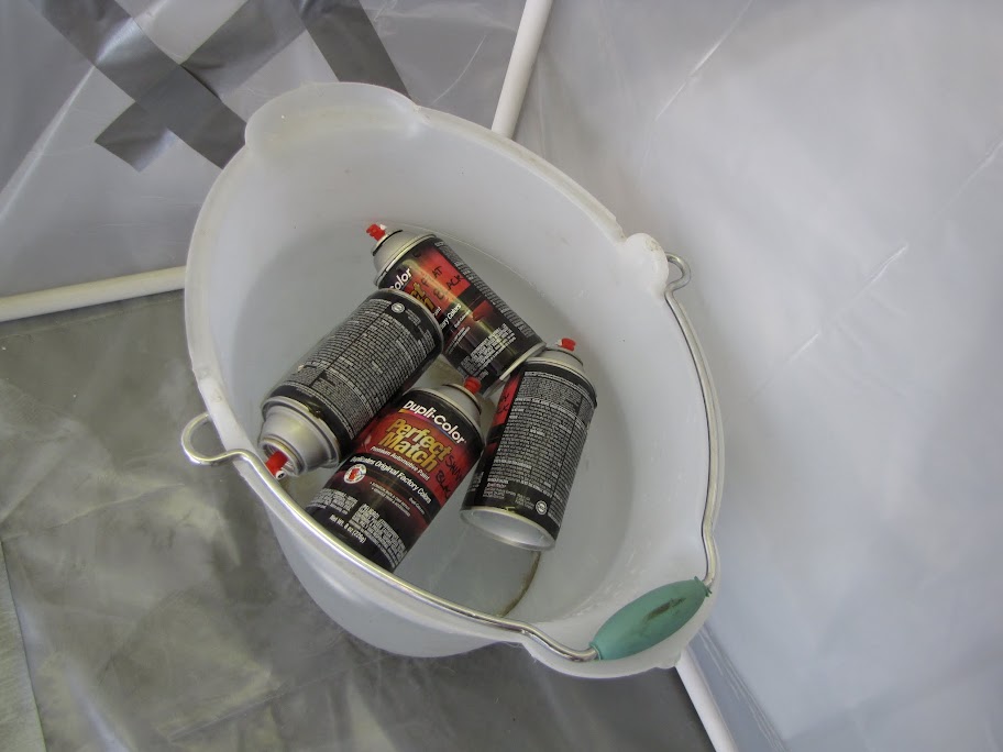
As mentioned previously, I was working on taking the paint off of my XSPC radiators... my first few attempts proved to be far too much effort for what should seemingly be pretty simple. After checking with some paint experts at the local hardware store, they recommended this stuff to me:
It is the weirdest material ever... kinda thick and goopy, like slime almost. According to the can, you lay it on thick and just wait... let the remover do all the work, then just come back later and lightly scrape it off:
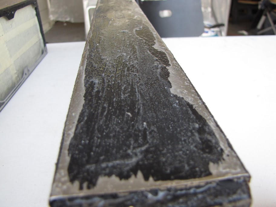
The painting people were right, though... this stuff is magic!
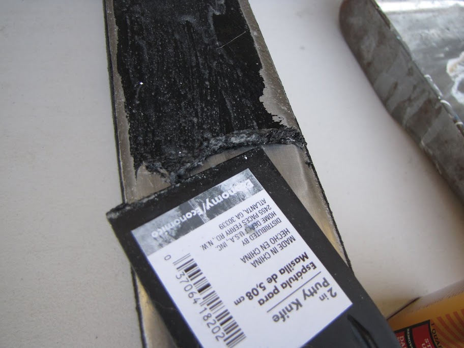
The remover and scraper got most if it... and I took care of the rest with some regular old thinner and an old toothbrush:
Voila!
So pretty... almost a shame I'm just going to paint them black again!
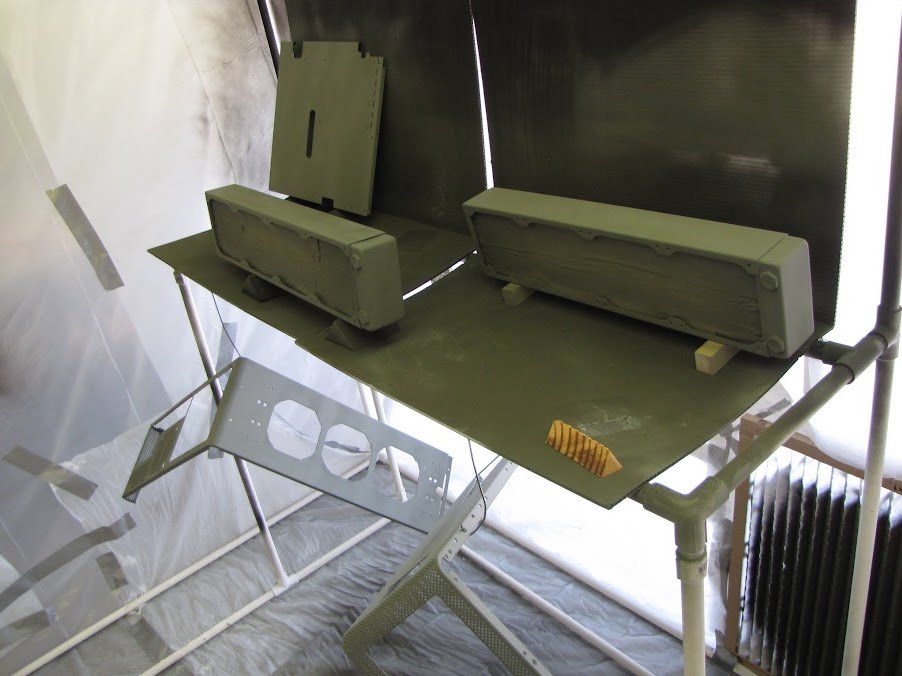
Back in the painting booth, I set up the two case walls, the bottom plate, and the PSU plate for their first coats of paint.
Using some tips I've seen around here and there, I soaked the paint in hot water... it's supposed to help the paint apply more evenly. My tests agree.
As mentioned, I used a pretty lengthy process for painting. I'll post my process from beginning to end after everything is through and it comes out well, but I am essentially laying down a north/south coat, waiting 15 minutes, then an east/west coat, waiting 15 minutes, another north/south, 15 minutes, and a final east/west, followed by drying for at least 24 hours. Once dried, I took the pieces out of the booth, wet sanded them down with P1500 sandpaper, let them dry, tacked them clean, and repeated the whole process one more time. Yea... it took a while.
Here's a sneak peek of the first coat drying in the booth:
Between coats of these four pieces, I continued to work on other small things. One thing that bothered me was how the front of the case came out after priming. I was hoping the primer layers would do a better job of hiding the front ports and the old area where the Lian-Li badge was... but it didn't. So, I went about sanding the face down with my mouse sander to get rid of the layers of primer:
Next, I filled the area with a coat of JB Weld (which has been working decidedly better than any of the other materials like Steelstick and Bondo) and let it dry for 24 hours:
The next day, I sanded it smooth with my mouse sander again:
Much more flat. Should be nice and smooth this time!
The following weekend (after letting the four parts dry in the booth for an entire week... not so much out of necessity, more because I just don't have time during the week to mod...) I laid out the four pieces from the previous weekend and prepared to give them the wet sanding with P1500 I mentioned above:
You can see the slight irregularities with overspray and such that make some areas look shinier or whiter than surrounding areas:
All in all, not bad for a first coat though. I went through and sanded all of it (maybe about 5-10 strokes over every surface... just enough to get rid of some of the 'noise' in the paint), then hung it up to dry off for an hour:
The paint is looking smoother already:
That's all for now... I still have to lay down my second coat of paint on these pieces, re-primer the front of the case as well as the radiators, and I haven't even gotten started on painting the internals for the case yet! Man... so much painting! :p
See you next time!
EVGA z77 FTW -- 16GB of Samsung MV-3V4G3D/US -- Intel Core i7-3770k -- EVGA GTX680 -- Corsair AX850 PSU -- Lian-Li PC-v2000b -- 2x XSPC RX480 Rads -- EK-RES-250 -- EK-DDC Dual Top/pumps -- EK-FC680EN Full Cover block -- Swiftech Apogee HD Block
Point of etiquette, is it too early to butt in and post demanding more progress? I keep coming back hoping to see an update and and keep getting disappointed.
Also, hi there California buddy.
Check back in about 8 hours...
EVGA z77 FTW -- 16GB of Samsung MV-3V4G3D/US -- Intel Core i7-3770k -- EVGA GTX680 -- Corsair AX850 PSU -- Lian-Li PC-v2000b -- 2x XSPC RX480 Rads -- EK-RES-250 -- EK-DDC Dual Top/pumps -- EK-FC680EN Full Cover block -- Swiftech Apogee HD Block
So I got a little distracted with my other project (Gemini, the HTPC build), but I finally have some progress to post!
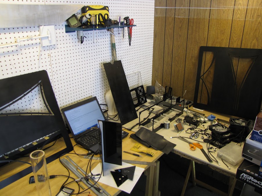
First of all, my workshop had fallen into a bit of disrepair since I started the other project... too many home projects like installing new lights in my house and replacing my water heater... gotta clean it up, so I can focus on my work! :p
With that out of the way, time to recap where I left off! Last time, I had finished putting a coat or two of paint on the case walls and PSU/bottom plates. I went over the finish with some 2000 grit sandpaper (wet, of course) one more time to clean off some of the dust that had accumulated and re-evaluate the paint job. I found a few spots that I wasn't quite satisfied with yet, so I put them back in the booth and gave them one more coat. 24 hours of drying in the booth later...
Some of the pieces came out looking great, like the PSU plate:
Others look a bit 'blotchy' around the edges, which I am not quite sure how fix just yet... perhaps more aggressive sanding?
Anyway, I put those aside for now to keep working on all the other pieces... back to the workbench! :p
As for the other pieces, I put some coats of primer on my radiators, the case housing, and the motherboard tray (really packing the paint booth to make some headway!
Afterward, I wet sanded the pieces with P1500, flushed them with clean water, toweled them off, and hung them out to dry:
One thing I forgot to do before priming the midplate was cut the holes for the reservoir and pass-through ports from the motherboard to the lower chamber where the radiators/pump will be. I started off by using the bottom piece of my reservoir to measure out where the holes would be :
As you may notice... the bottom of the reservoir is no longer attached to the reservoir. In fact, the reservoir got completely disassembled thanks to my clumsiness.
Anyway, back to the midplate... I made some crude markings to get a rough location, then drew a more exact box around it to give myself some slack.
My thought is that I am going to fit the reservoir in place, then screw the fittings into it from the bottom of the midplate, so they will essentially hang through the midplate without actually screwing on to it. This greatly simplifies the design I was originally considering, which I'm all for.
The box ended up being 25mm, which was almost exactly right for using a quarter to round off the edges... so that's what I did.
A little bit of work with the Dremmel later, and I had my rough cut:
Now, I just need to work on it a bit with the files to clean it up... but I'll save that for another day.
Next, I took some measurements on the midplate for the PSU, cabling, and through ports, and marked off the area where I would drill the ports. In case it isn't clear, these ports will allow the water to flow from the bottom chamber with the radiators and pumps up to the top chamber where the motherboard and blocks will be, and then back down into the reservoir:
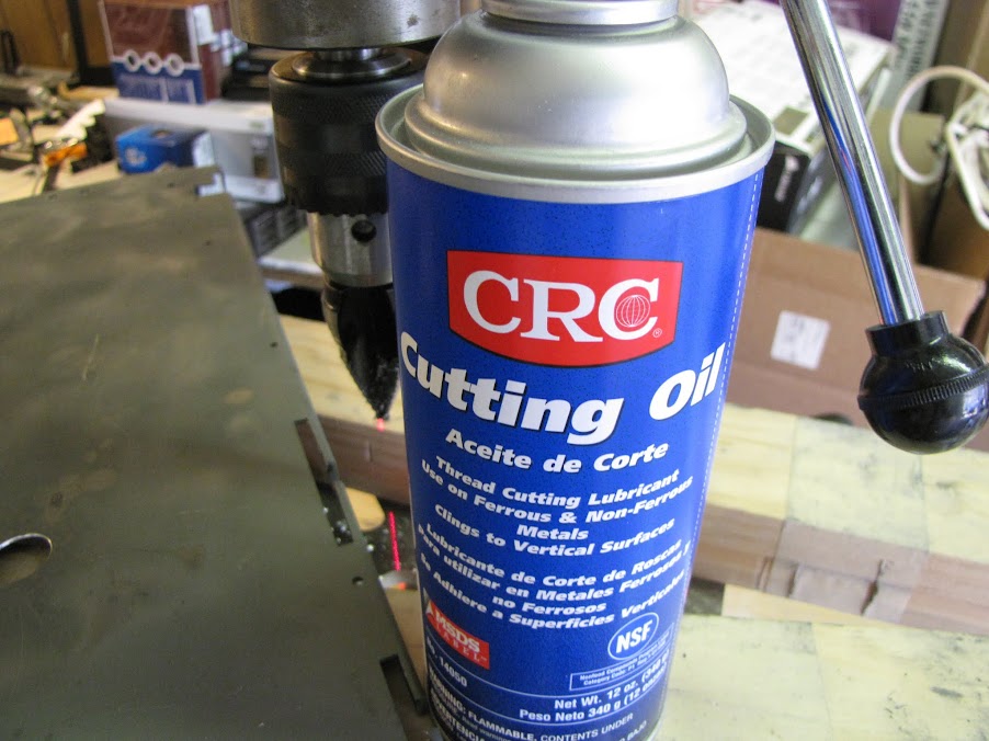
To make these cuts, I decided to go with my drill press and the handy Unibit. I also got a hold of some new cutting oil that is technically for cutting threads, but also supposedly works well for machine bits.
I expected this stuff to be pretty much like WD-40... but eww... it's weird. It's like a slug made of foam!
The fortunate part of this weird lubricant foam was that it stuck to the sides of the bit perfectly, making it super easy to apply without over-applying (like the last time I used cutting oil to cut the holes in my reservoir...
Now this piece is ready to clean, re-prime, and paint I think!
Speaking of paint...
I put the first few coats on the case shell, and it's drying for 24 hours now. I still have to do the 'inside' of each piece, wet sand it, put down a second set of coats, wet sand it, and see if it needs a third or not. Painting takes a long time! :p
Anyway, that's all for now! Good to be back!
EVGA z77 FTW -- 16GB of Samsung MV-3V4G3D/US -- Intel Core i7-3770k -- EVGA GTX680 -- Corsair AX850 PSU -- Lian-Li PC-v2000b -- 2x XSPC RX480 Rads -- EK-RES-250 -- EK-DDC Dual Top/pumps -- EK-FC680EN Full Cover block -- Swiftech Apogee HD Block
Progress report time!
I spent a day or two this past week focused on painting, and was able to make some nice headway! I started by cleaning up the holes that I cut in the midplate from last time, which will allow the reservoir and pass-through fittings to go between the top area of the case and the bottom area. I just used some fine metal files, followed by some 600 grit sandpaper to smooth the edges:
Next, I wet-sanded down the midplate to clear up some of the cutting oil residue and whatnot, in preparation for giving it a re-coat of primer:
Double checked the cuts with the fittings to make sure they lined up the way I intended (you're looking at the underside of the midplate at the moment):
... and back in the booth for some more priming!
While waiting for that coat of primer to dry, I went on to re-evaluate the coat on my case walls. There are some strange effects going on that are hard to capture... I think part of it is that the brushed aluminum pattern from the case wall is showing through the primer and paint, giving it a striped appearance that you can kind of see in the center of the picture here:
I re-sanded the pieces to try and get rid of some of the blotchy-ness from the first few coats that I think was ultimately due to being too stingy with the top coat, and I will be laying down another few layers of paint on these pieces to try and clean that up.
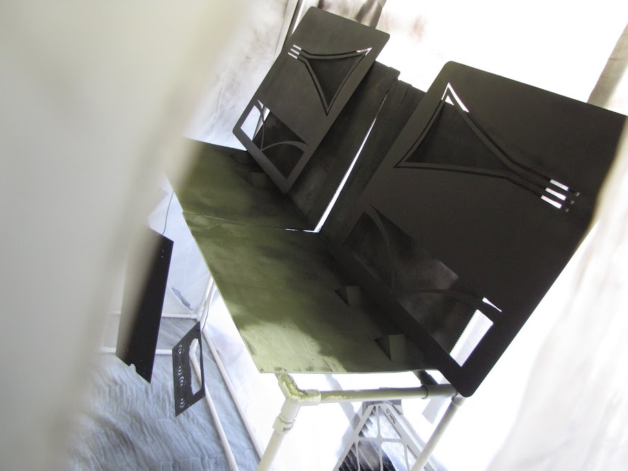
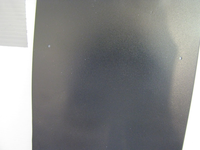
In the meantime, the primer coats on the internal pieces completed drying, and I moved on to painting them as well. These pieces are what I refer to as "internal" parts, in that they are not visible from the outside of the case (for the most part) when it is completely assembled. For these pieces, I decided to paint them with a "flat black" paint from Duplicolor that ends up drying to look just barely not black... almost a really dark grey. Darker grey than MDPC Shade 19. The look is subtle, and I probably won't have the photography skills to capture the difference adequately... but it looks nice. :p
Here's the radiators in the booth, getting their top coats:
The process I followed was to first put down a light dusting... just enough to cover the primer, but you can still see the primer through it. After 10-15 minutes, I would put down another coat moving in the opposite direction (so up/down if the last coat was left/right), this time with a bit more paint. Finally, I would lay down a third coat, this time with much more paint ensuring full coverage, but not so much that it pooled or ran or anything... just overlapping about 50% of the previous line to get a nice continuous coat. After the top coat dried (I gave these pieces over an hour, which is all the directions on the can recommended) I looked over the coats to make sure there weren't any defects, lightly clean off any dust that settled with a tack cloth, the put it back in the booth for the clear coat.
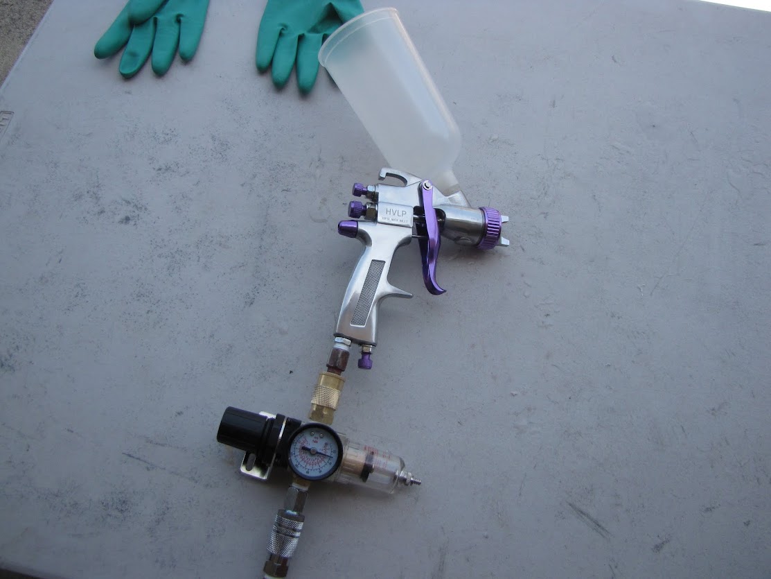
To clear coat, instead of using spray cans, I ended up using a compressor and a spray gun. The primary reason being, I wanted to use a matte clear coat for these pieces to keep the matte appearance, and I couldn't find any good matte spray cans for Duplicolor paints. Fortunately, my dad had both a spray gun and a compressor to borrow... but the gun is old school, and I'm considering getting my own:
I also have my own compressor, but it's smaller and has a hard time keeping up with extended spray sessions, so I borrowed his (which is massive.) Only issue with this one is that the lowest pressure setting is 40 PSI, which is the maximum rated for the clear coat I'm using.
For putting on the clear coat, I used 3 passes, much like the paint; the first coat was light, the second medium, and the third heavier with a 50% overlap.
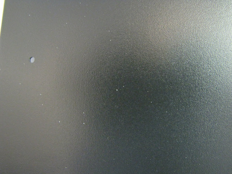
I noticed a little ways into laying down the first coat that for some reason, I was getting a lot of little white specks on the clear coat... it looked like residue from the gun or something. I cleaned the gun out well with water and dried it / ran it empty before putting in clear coat... my only thought was that maybe the pressure given by the compressor was too high:
I went ahead and switched it out for my compressor, but it didn't seem to make a lot of difference:
I wonder what's wrong?
The only way I found to counter it really was to lightly rub it down with a tack cloth after waiting 10 minutes for each coat to dry... which got rid of most of the white dots, but a few still remained. I'm probably going to have to lightly wet-sand these coats to try and get rid of the dots, and see where I am from there. If I need to put another coat on, I will probably get my own HVLP air guns and try again. If it ends up looking good after a light wet-sanding though, I may just call it good.
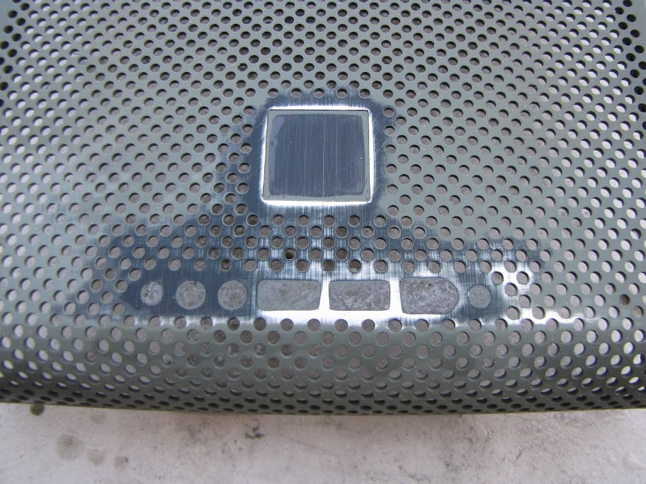
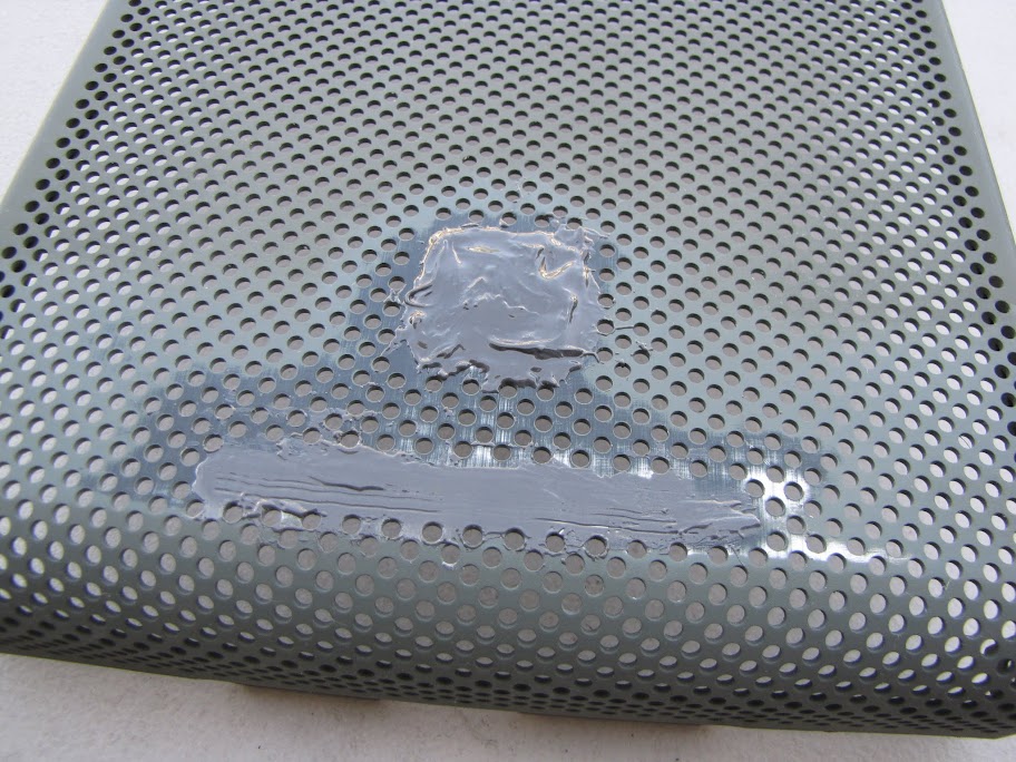
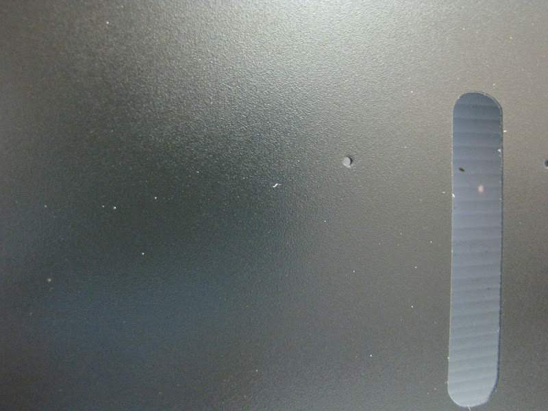
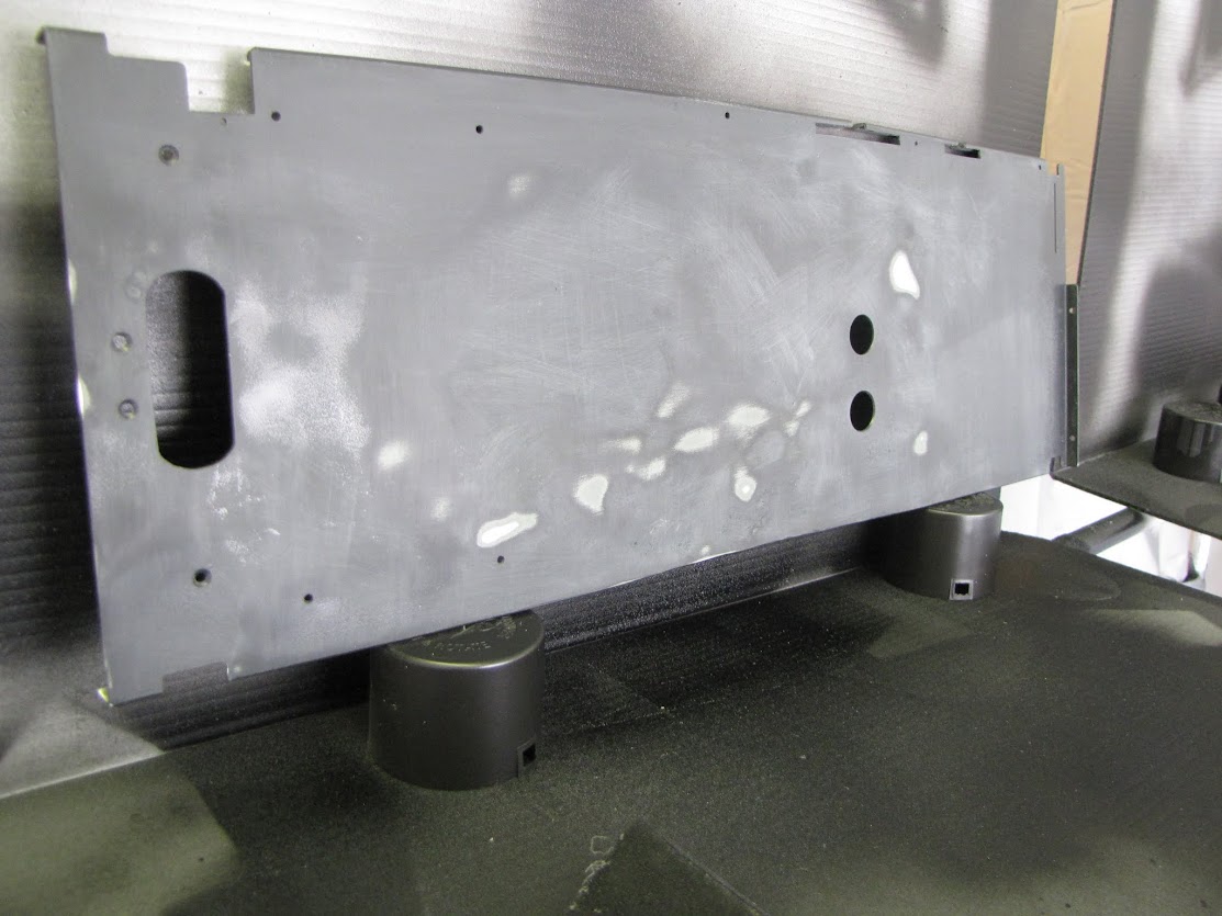
Anyway, some of the pieces came out actually looking pretty good... others (like the motherboard tray and midplate) have a lot of white dots and will need to be redone I think. I took some pictures, regardless.
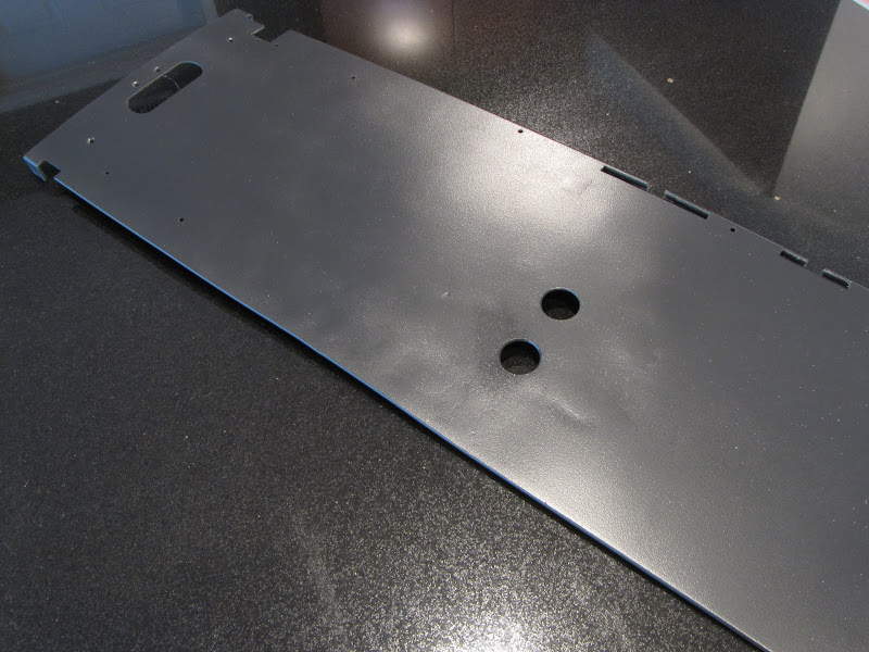
Here's the midplate... you can see a few of the white specks. Granted, a motherboard will be obscuring the entire plate from corner to corner... so you wouldn't see it... but I'll probably still redo this one. I'm obsessive like that.
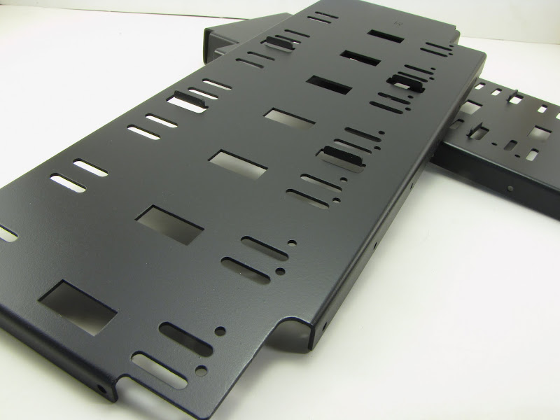
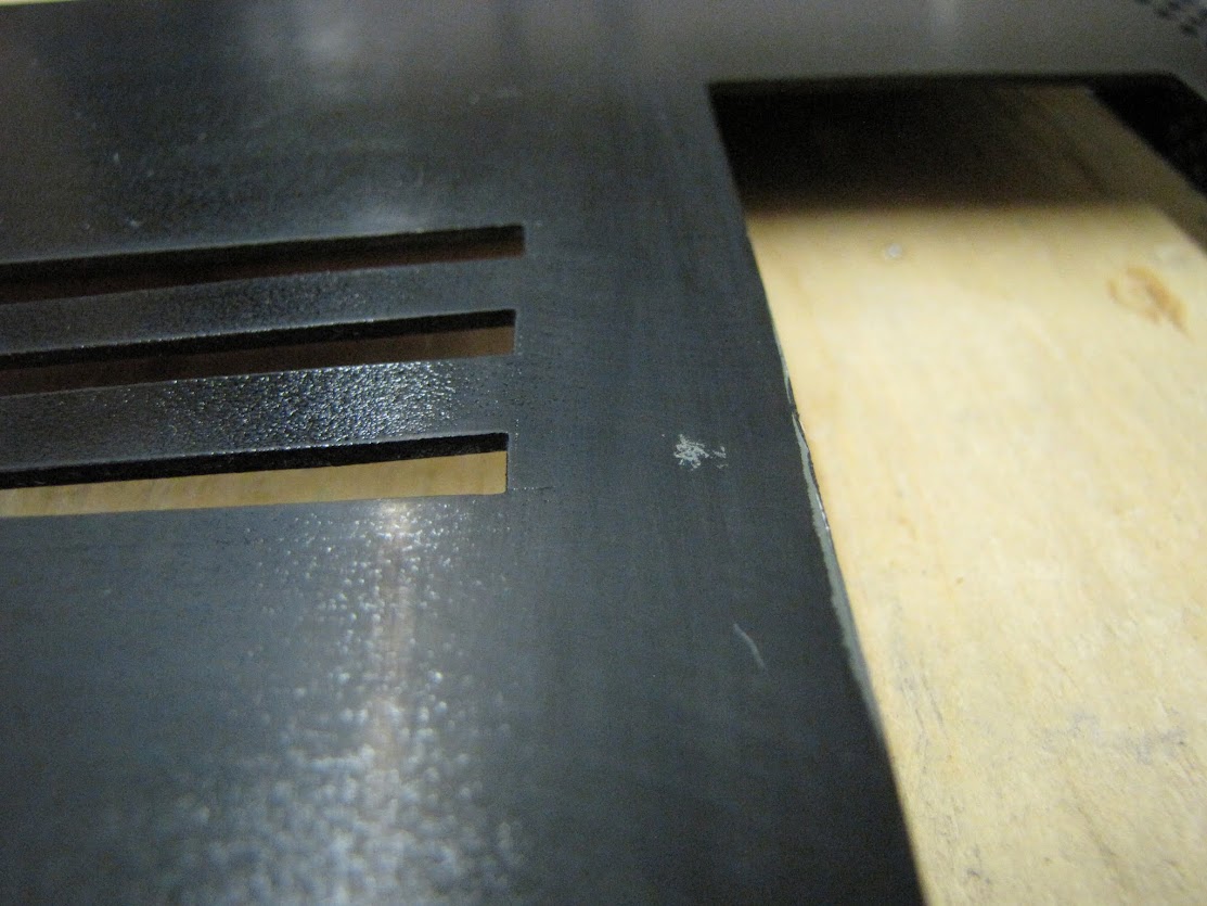
Here's the hard drive holders... which really aren't hard drive holders anymore, as the whole area will be taken up by the reservoir. They're more of "structural integrity" pieces now. I managed to clean up the white dots on them pretty well, so I think these are keepers.
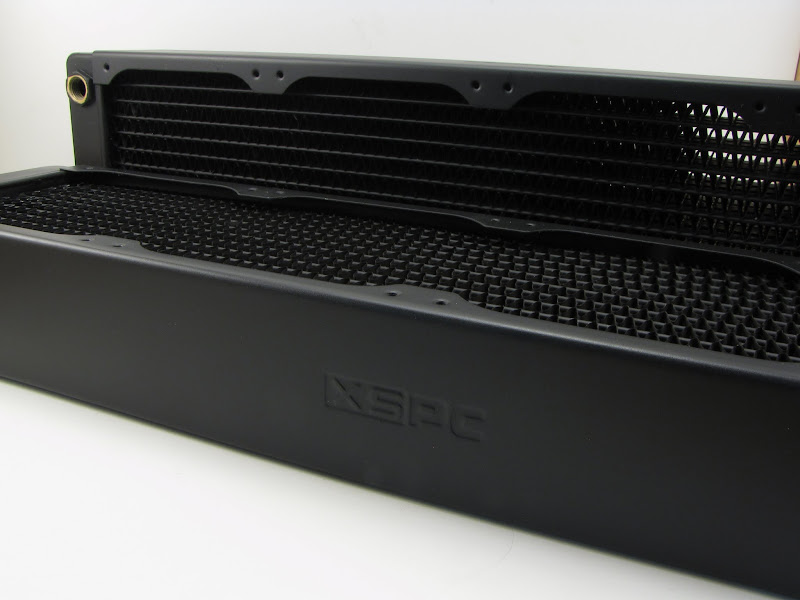
The radiators came out fairly nicely as well, so fortunately I won't have to redo them. They also will be mostly obscured by the radiator housing I built earlier on... all but the top edge, that shows "XSPC". Why did I go to all the trouble of painting them? Because!
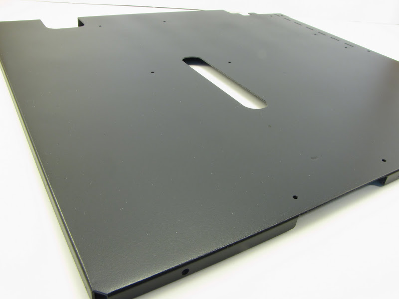
And finally, the midplate... which is too large for my ghetto little photo booth... so it gets a 'kitchen counter' picture instead. :p
Next up... cleaning up the white speck issue somehow on these pieces, a few additional coats on the "exterior" pieces of the case, clear coats for them, and re-assembly! Until next time!
EVGA z77 FTW -- 16GB of Samsung MV-3V4G3D/US -- Intel Core i7-3770k -- EVGA GTX680 -- Corsair AX850 PSU -- Lian-Li PC-v2000b -- 2x XSPC RX480 Rads -- EK-RES-250 -- EK-DDC Dual Top/pumps -- EK-FC680EN Full Cover block -- Swiftech Apogee HD Block
Hello Hello!
It's been far too long since my last post... unfortunately work has gotten crazy the last month or two, and it's leaving very little time for hobby fun. Alas, sometimes you must do what you have to in order to do what you want to... which is modding!
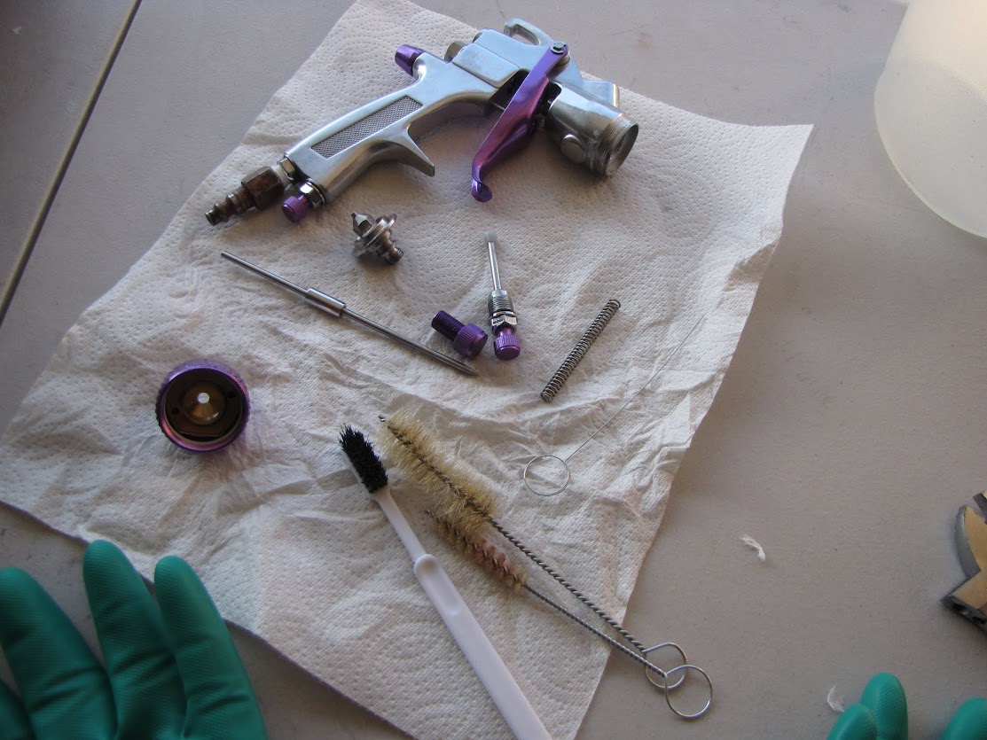
So, when we last left off, I had put down some matte clear coat on my matte black "inside pieces", and I had a weird issue with white specks being embedded in the surface. After some searching around online, I ultimately concluded that it had everything to do with my cleaning process... which was to follow some very poor advice online and just spray thinner through the gun and call it a day.
It's not an overly expensive setup, but it's better than the old unknown spraygun that my grandfather originally purchased to spray his farm equipment with.
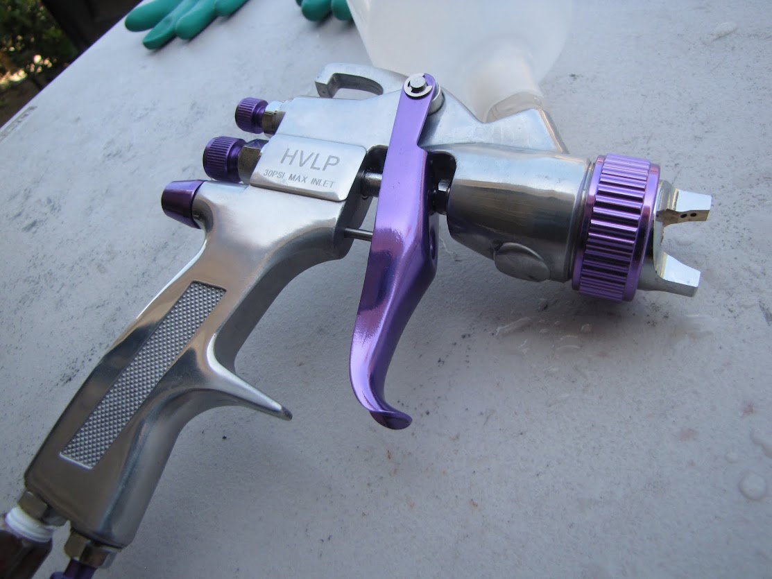
The spray gun kit came with two such guns... one small HVLP version for doing finishing work and small stuff, and one large HVLP version for doing higher volume stuff. It also came with many "nice to have" items like a cleaning kit, some disposable paint cups, and multiple nozzle sizes from 1.2 up to 1.8. It was a real steal at the local hardware store, too. I researched the gun a bit online first, and it appears to be a very popular one commonly referred to as "the purple gun" which is cheap and medium-low quality by default... but with a bit of customization and TLC ends up being a great gun!
Most of the modifications included replacing the plastic washers (or in many cases, non-existent washers) with some nice new nitrile washers, and replacing a lot of the spray-on thread goop with some nice quality teflon tape. $5 in spare parts with a little labor to turn a chump into a champ? Absolutely! :p
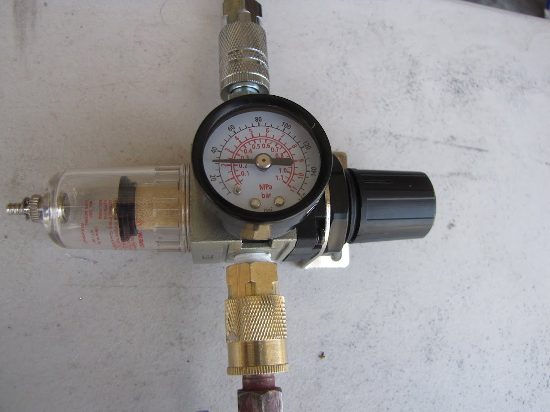
The other piece I bought for this outfit was a pressure regulator and air filter / water remover kit... which greatly improves the quality of the job by tightly regulating air flow and removing any contaminants and moisture in the air supply.
This stuff probably cost me no more than $20 at the local hardware store, too. Well worth it! Anyway, more on this gun later.
The other issue I was having last post was that I could see some 'patterns' in the shiny black pieces that gave the finish an odd effect... one that certainly wouldn't work out well for the mirror finish I wanted to achieve on my case exterior! I ultimately determined that the issue with these patterns showing up was that I was a bit too stingy on the amount of paint I was using. Everyone says to put only multiple light coats on... but I think perhaps my version of "light" was closer to "transparent".
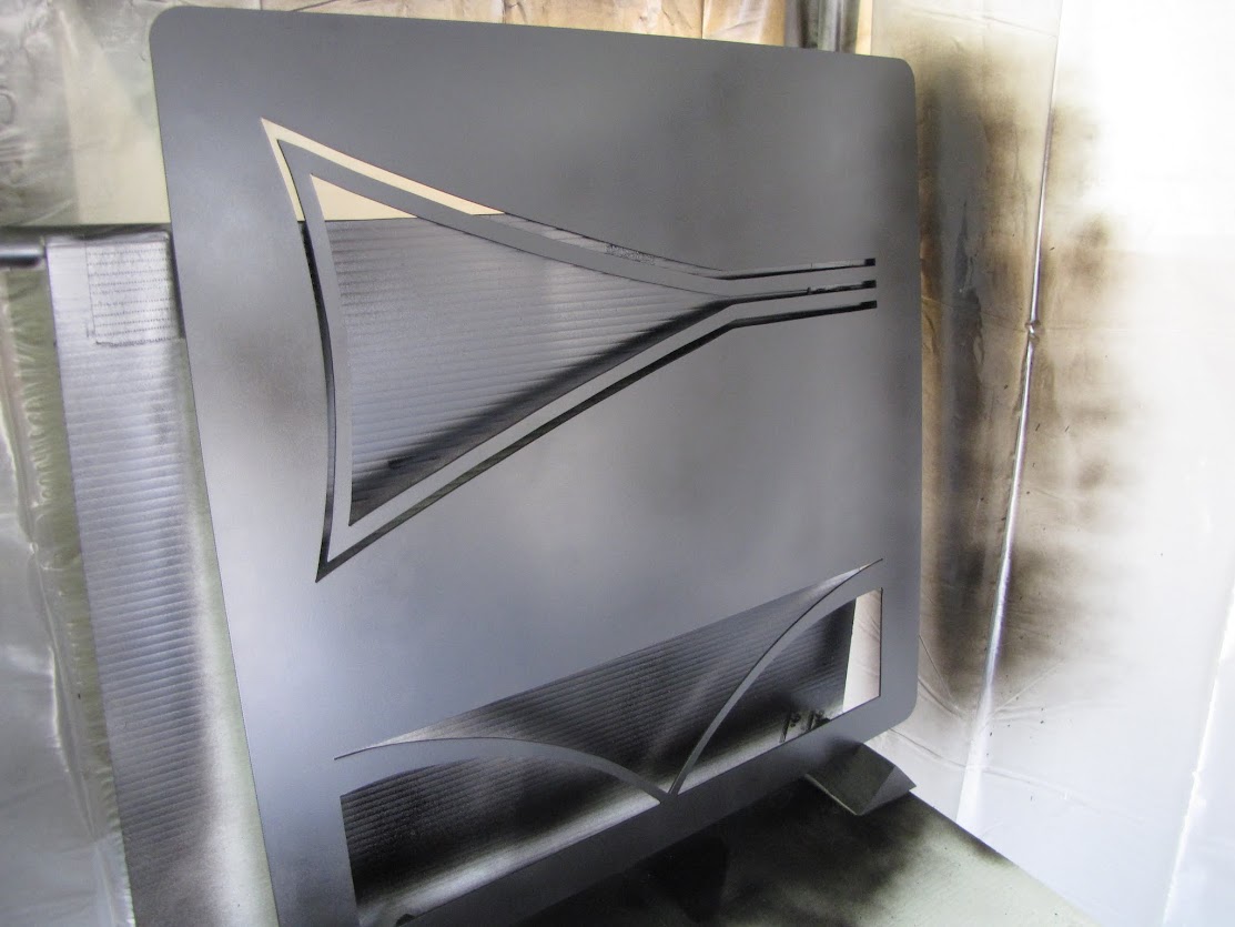
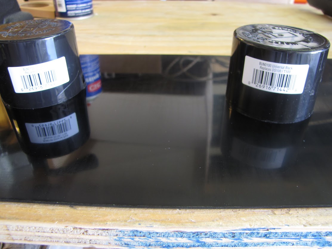
Almost no more lines, and a much healthier "shiny-er" black. This was just the first pass, and I did two more passes of similar weight switching from up/down to left/right each time. I let that business dry in the paint booth for about 30 minutes before moving on to the next step... clear coat!
Here's the first couple coats of gloss clear drying on the case doors:
Of course, a few specks of dust settled on the surface despite my booth and all the precautions I took... but these easily came off with a wipe of a rag after I let the parts dry for 24 hours, so no big deal. I let the parts dry for about an hour or so in the booth until they were no longer tacky, then lightly took them out and set them on the bench to dry for a day or two.
My camera skills don't really reveal, but the spray gun so far has done an excellent job of laying down a nice smooth finish. There is orange peel, of course, but I've come to understand that orange peel is just a reality of painting.
I went on to lay down paint and clear on the remaining pieces, and stood them up around my garage wherever I had room:
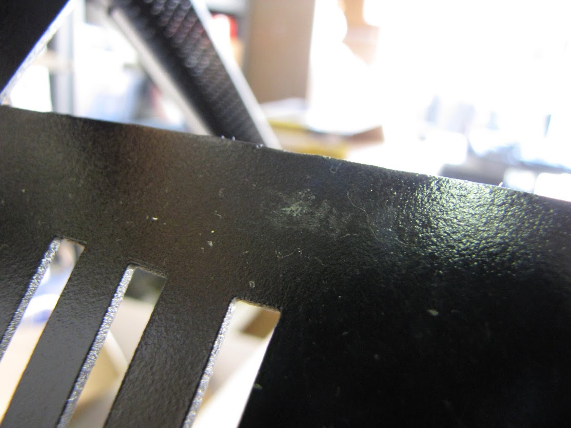
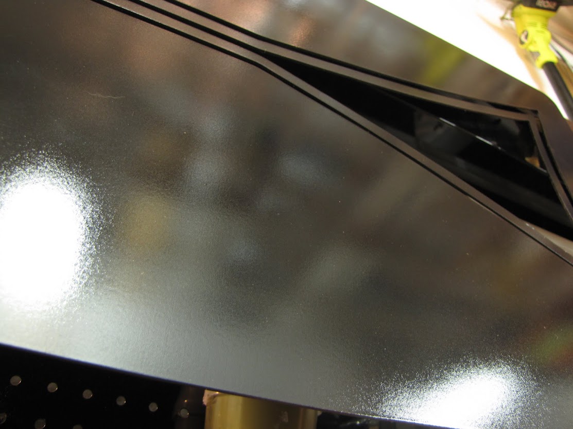
Things were going so well... but of course, the very last piece had an issue. I saw it happen in slow motion... spraying a sweep of clear over the last (and of course, most important/visible) part of the case, a lonely strand of hair floated between the piece and the spray gun, and it was adhered to the surface deep under a layer of clear. I couldn't leave it there, or it would dry between the clear and color coat... giving very little chance of rescuing the finish. I didn't want to have to re-do the whole piece, so I did my best to pull the hair out of the clear... but unfortunately, it messed up the color coat anyway:
It's always the last piece!
Of course, I spent the time breaking down and properly cleaning my gun in preparation for another long day to come!
The next day, I sanded the affected area down to flat using some P600 wet sand paper, trying to avoid going all the way back to bare metal, which would require me to start over with the primer coat again.
I then went on to lay down another triple-set of color coat, followed by a set of clear coat. Fortunately, it completed safely this time without any stray hairs. In addition to this marred piece, I decided to redo my midplate as it had too much of that white speckled stuff to save. I sanded it back down to bare metal and re-primed it.
I briefly checked on the other pieces to see how they were drying... partly to remind myself that the extra effort makes it worth it. Drying nicely...
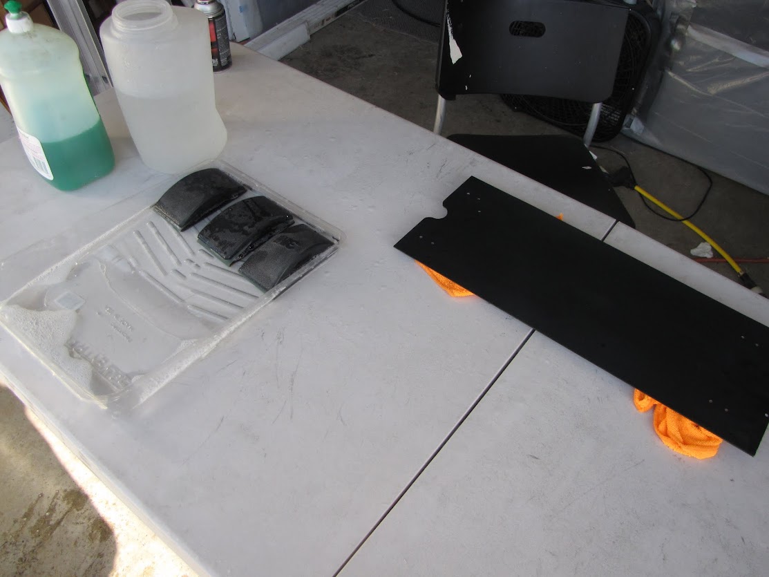
The following weekend, I decided to work on sanding down the orange peel in preparation for that long sought-after mirror finish. I set up my sanding table and blocks for what I hoped to be a short day:
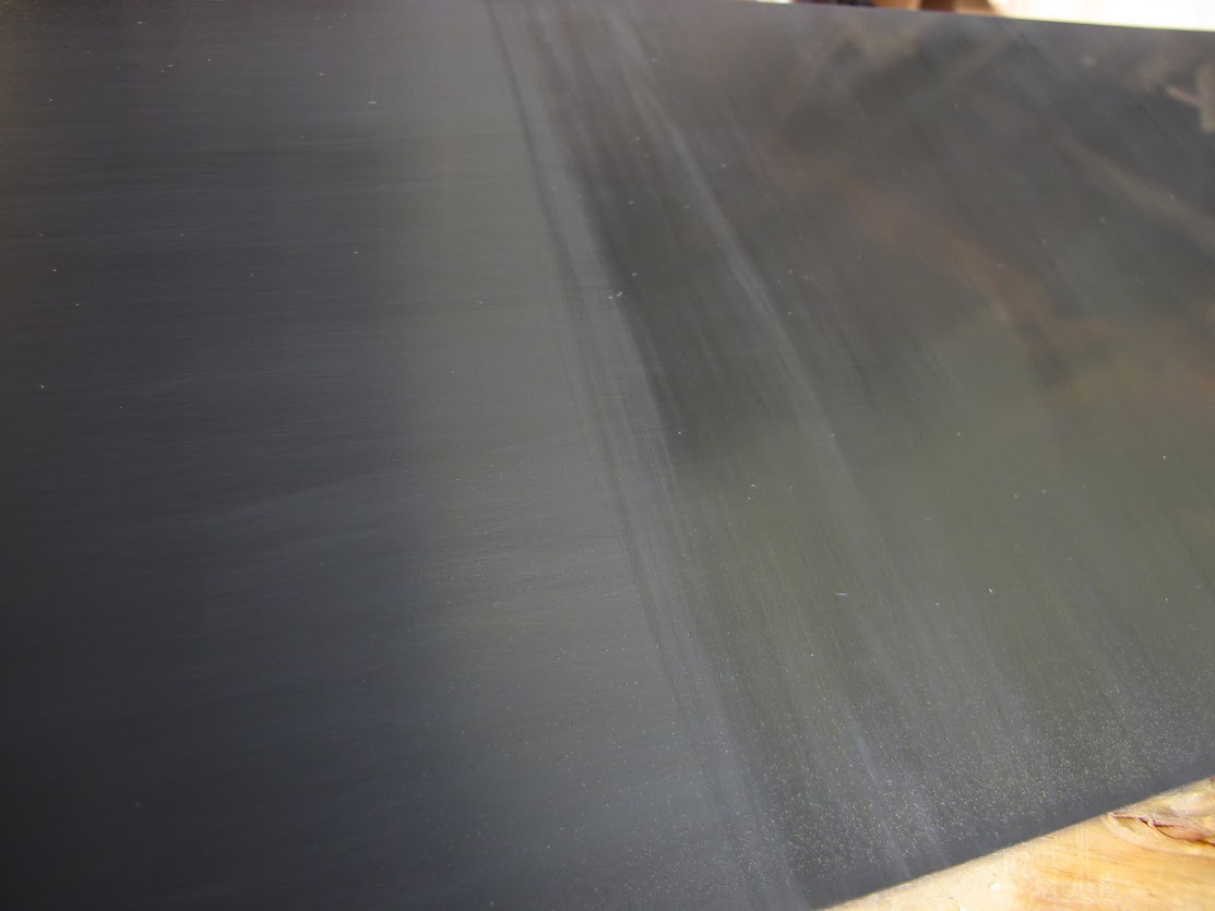
I started out with some 2000 grit sandpaper, water, and a dab of soap for 15-20 passes lightly... barely any pressure, more letting the block slide than anything:
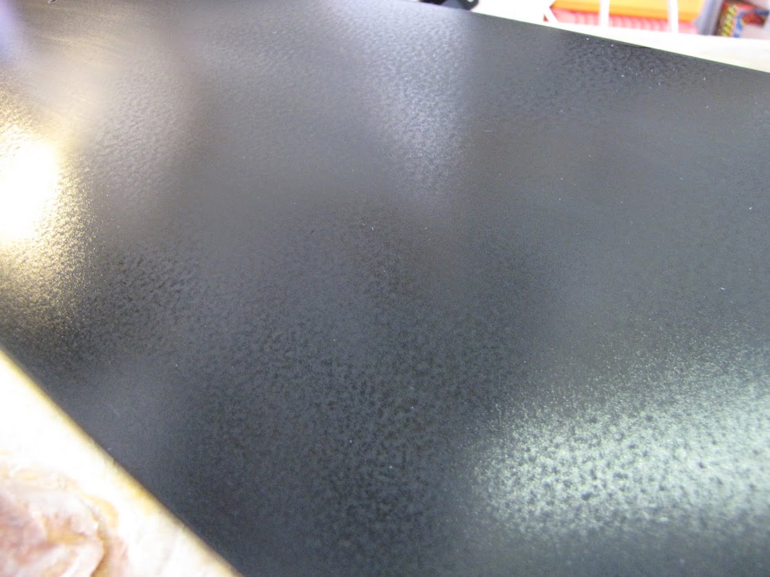
Only enough to scratch the surface.All the shiny spots are pits that need to be sanded down. And this is only one small piece of the case. I have a looooong day ahead of me.
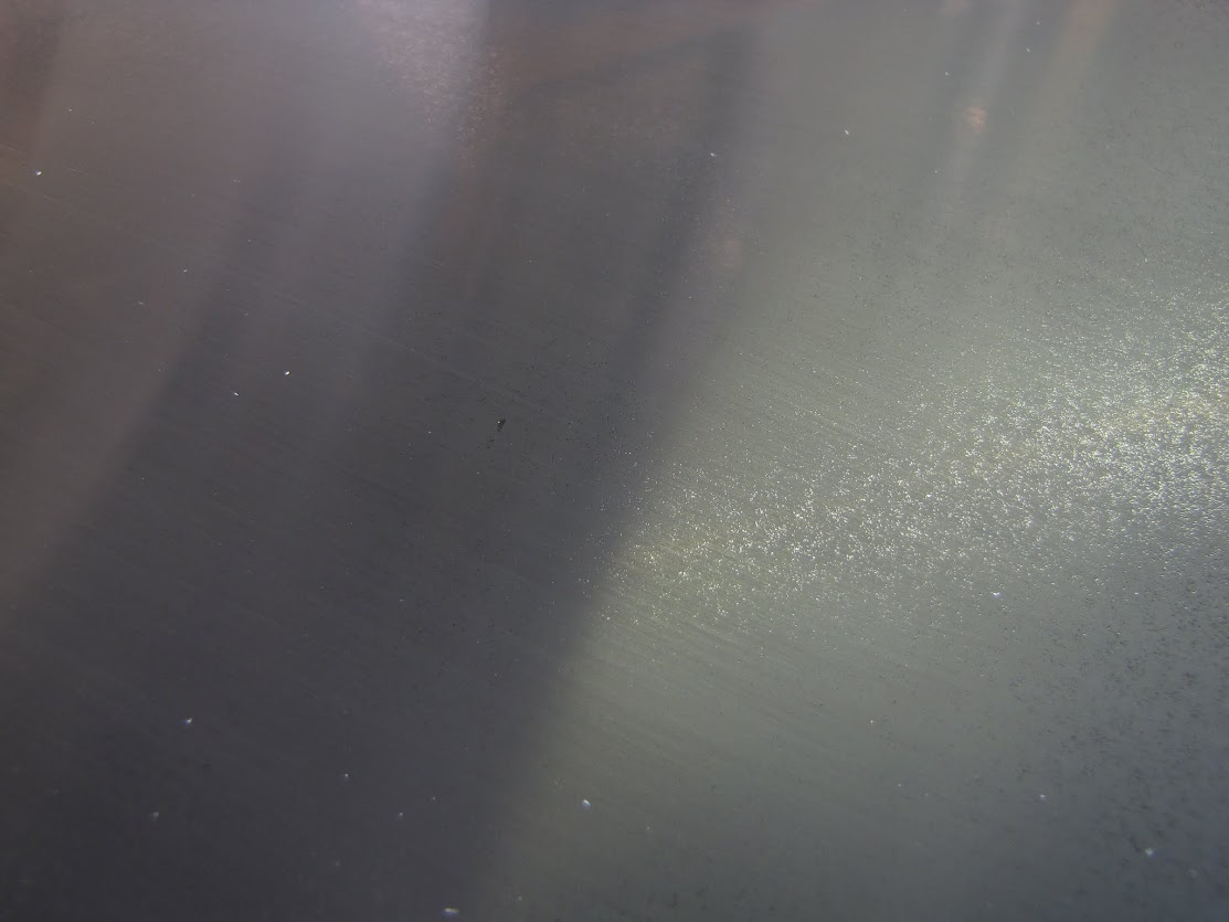
Some spots are there... but still tons of tiny speckles. After a lot more careful sanding at 1500 to get rid of all the pits, I switched to 2000 and changed directions as well:
Note, I left the orange peel along the edges for now. In this shot, I was just focusing on the center and making sure my process was going to work right. You can see that the right side that has been done by 2000 grit is starting to get a little shiny, where the left that was done by 1500 only is just hazy. I sanded a bunch more with 2000 grit until I could no longer see the horizontal lines from the 1500, then went to work with a microfiber cloth and some polishing compound meant for cars:
Getting there!
Needless to say, I have a lot of sanding and polishing to do. Until next time!
EVGA z77 FTW -- 16GB of Samsung MV-3V4G3D/US -- Intel Core i7-3770k -- EVGA GTX680 -- Corsair AX850 PSU -- Lian-Li PC-v2000b -- 2x XSPC RX480 Rads -- EK-RES-250 -- EK-DDC Dual Top/pumps -- EK-FC680EN Full Cover block -- Swiftech Apogee HD Block
A little off topic... but Bitspower notified me that they are releasing a new DDC top that's clear/frosted acrylic with a tube reservoir built into the top. Check it out here. I got notified early via my sponsorship, so I figured I would share the news.
I've always thought about picking up something like this for a HTPC project or smaller case, where there really isn't much room to be putting in a reservoir or something. I take something like this, mount it to a desk or more visible surface, and run tubes back to the case (which rarely moves anyway) where it would hook into some quick-disconnect thru-ports or something...
I really should stop thinking about more mod projects while I still have so much left to do on this one... :p
Last edited by Noblesoft; 06-30-2013 at 02:51 PM.
EVGA z77 FTW -- 16GB of Samsung MV-3V4G3D/US -- Intel Core i7-3770k -- EVGA GTX680 -- Corsair AX850 PSU -- Lian-Li PC-v2000b -- 2x XSPC RX480 Rads -- EK-RES-250 -- EK-DDC Dual Top/pumps -- EK-FC680EN Full Cover block -- Swiftech Apogee HD Block
 Posting Permissions


 Reply With Quote


Bookmarks