Page 3 of 6 FirstFirst 123456 LastLast
Results 51 to 75 of 134

Thread: Project Prism - A Lian-Li PC-v2000 Worklog

  1. #51
    Registered User
    Join Date
    May 2012
    Location
    California
    Posts
    96
    Allll righty! Time for some pictures! I'll spare you the dialog and jump right into it, commenting as I go and letting the pictures do most of the talking.

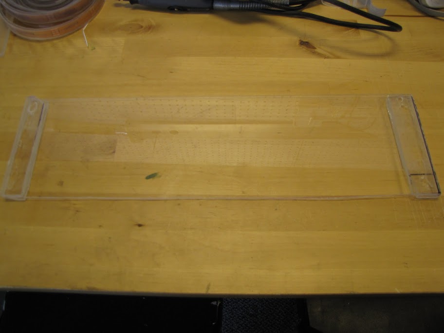
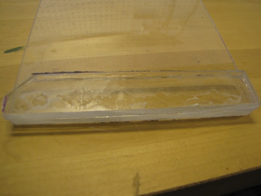
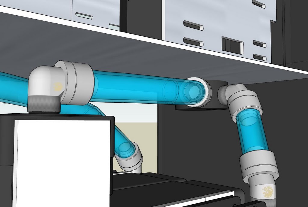
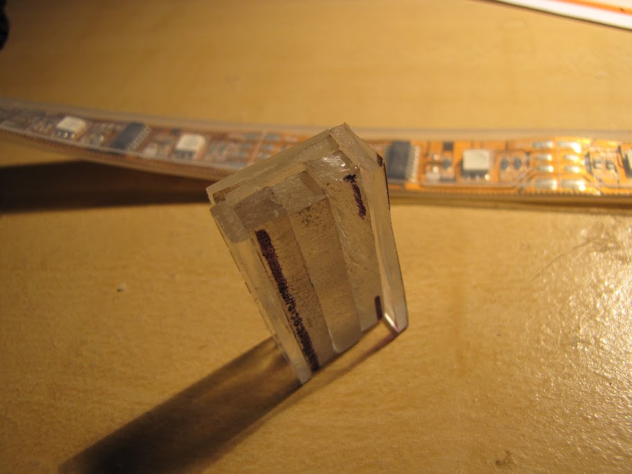
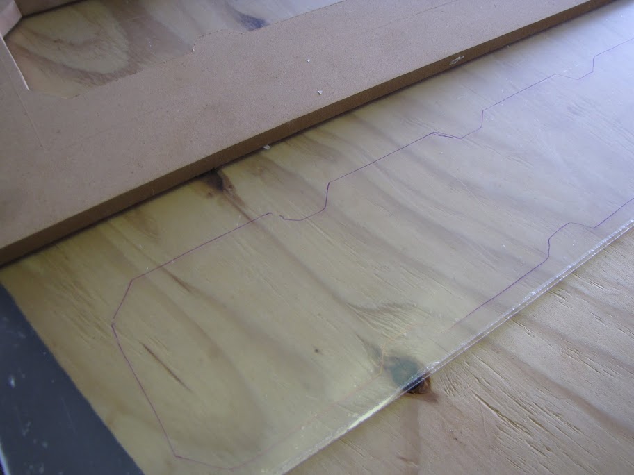
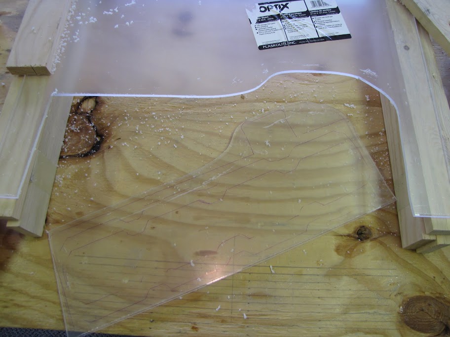
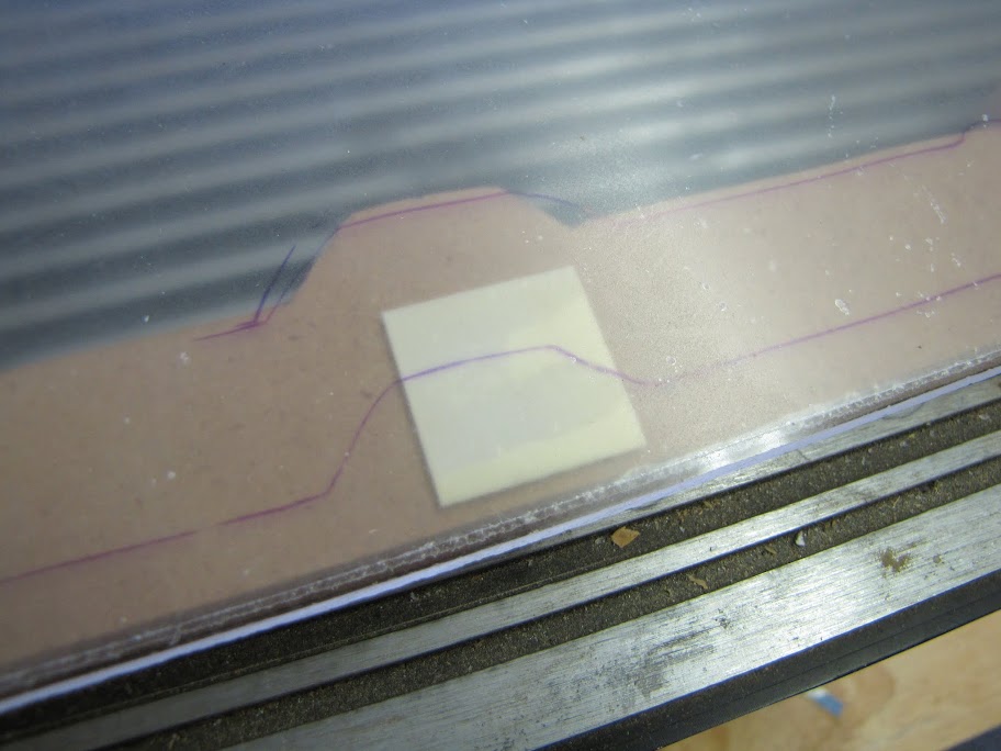
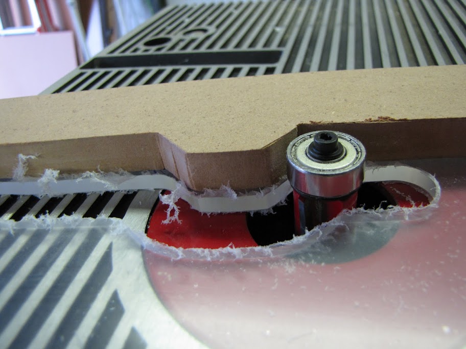
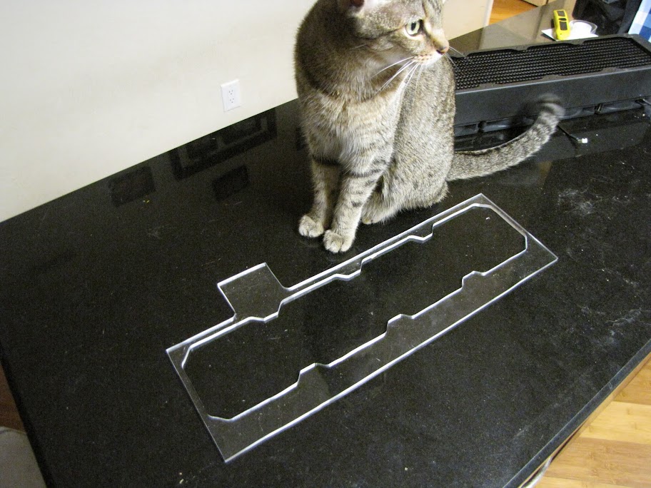
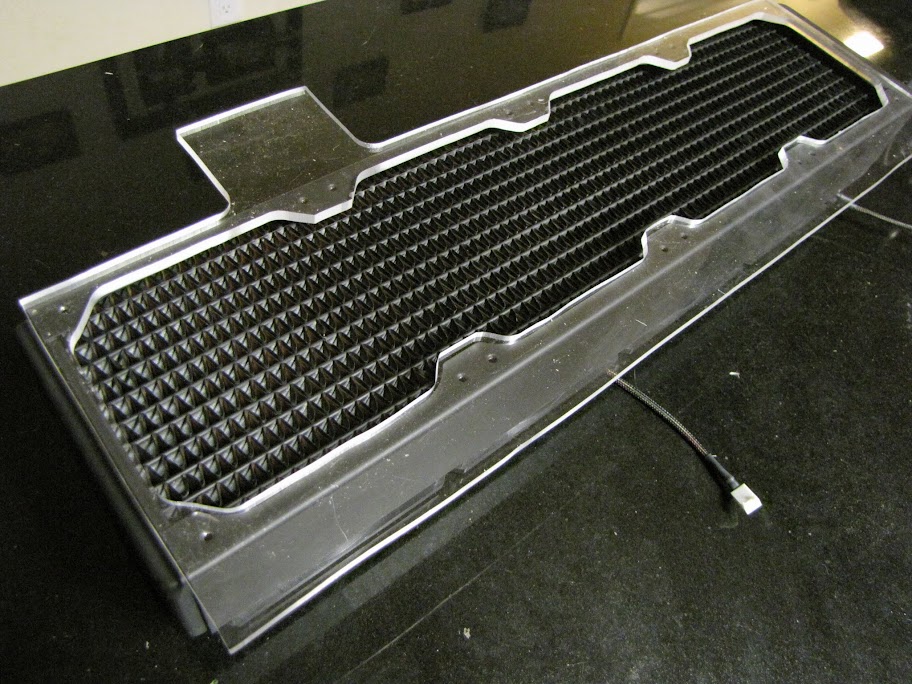
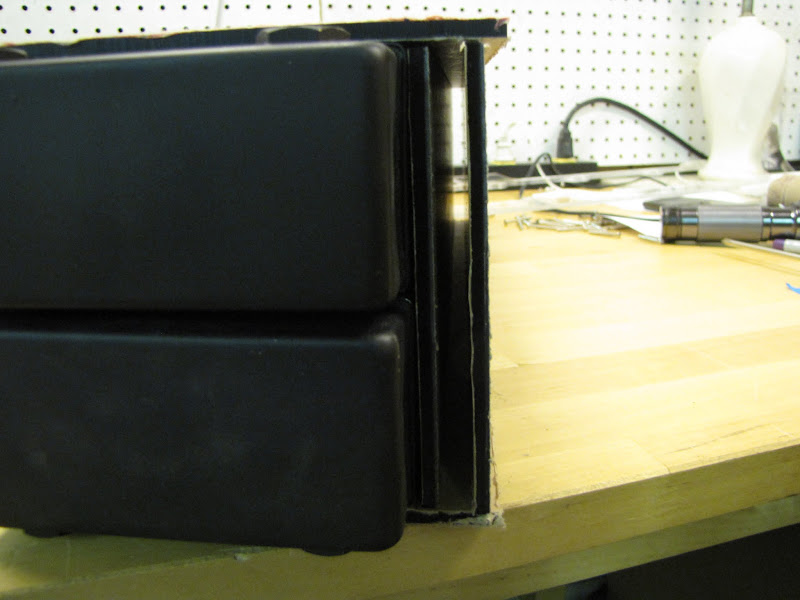
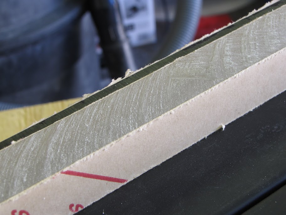
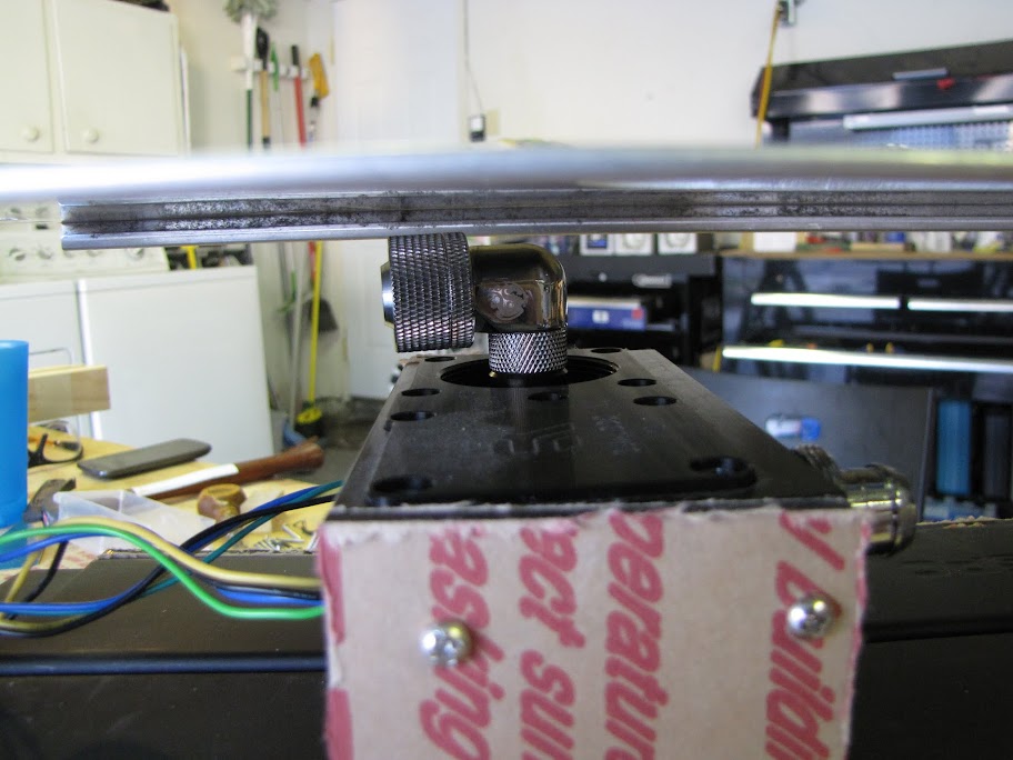
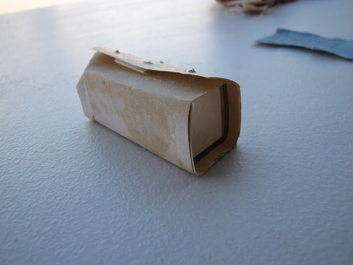
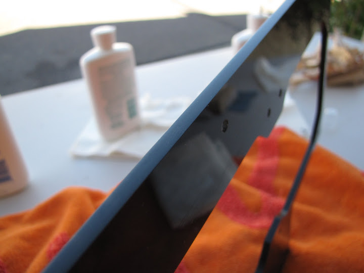
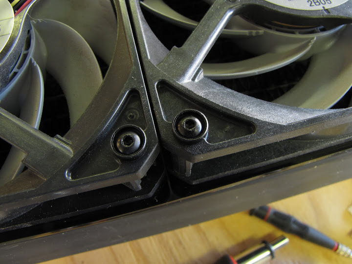
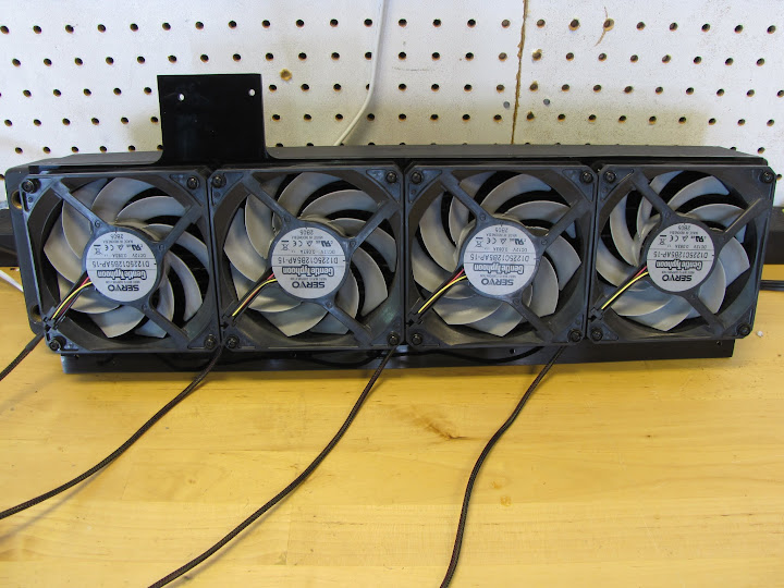
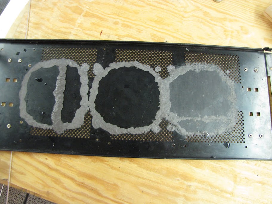
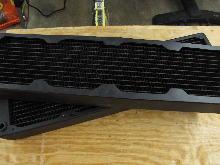
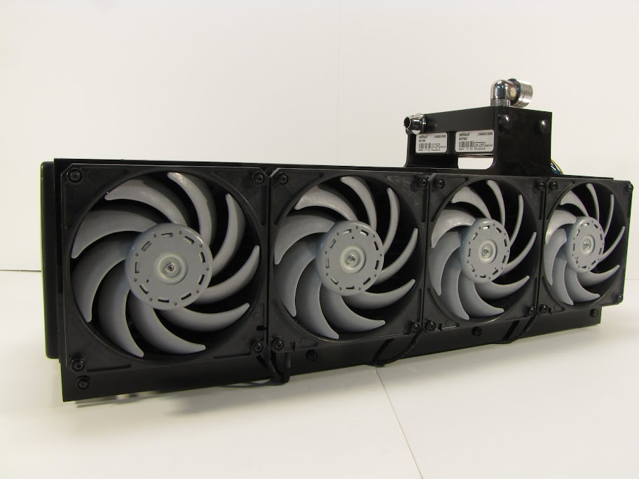
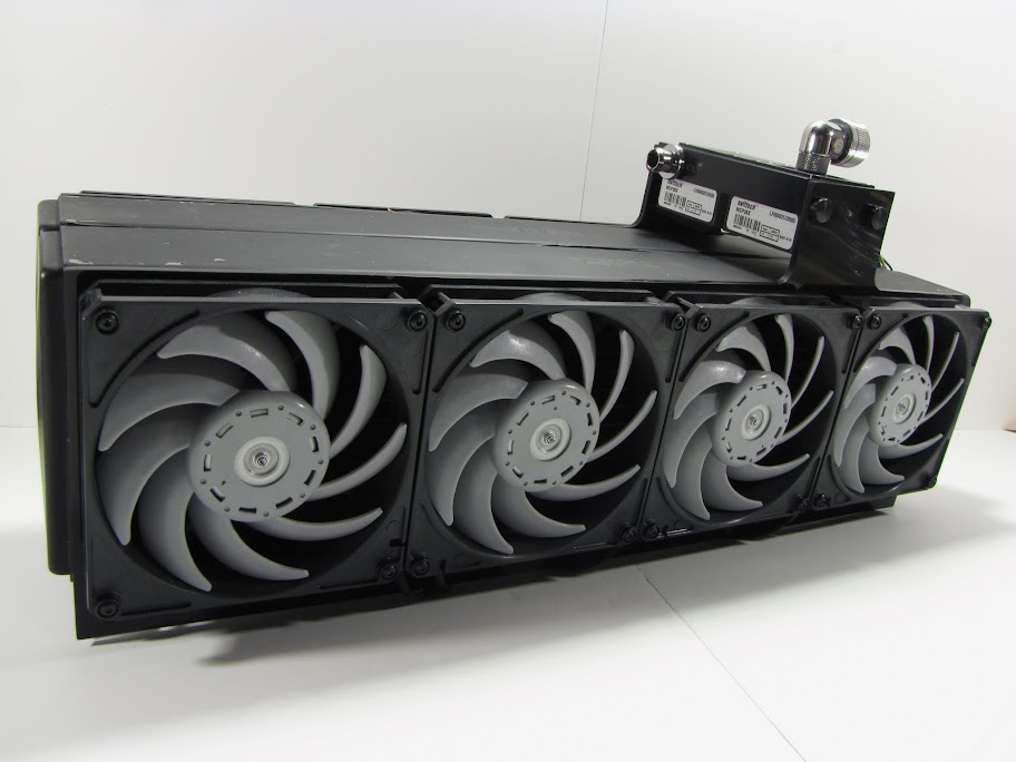
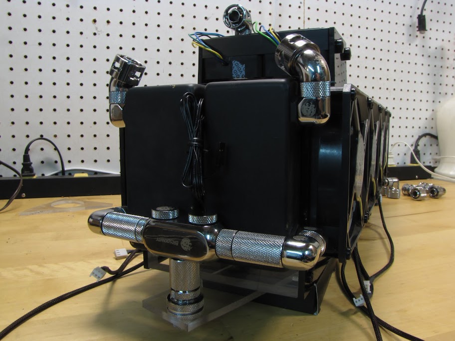
    First of all, here was that picture I promised of the crude acrylic barrier I made for the radiator testing:


    It also served to show just how ugly an acrylic weld with superglue can be!


    Anyway... on to the case cutting process!

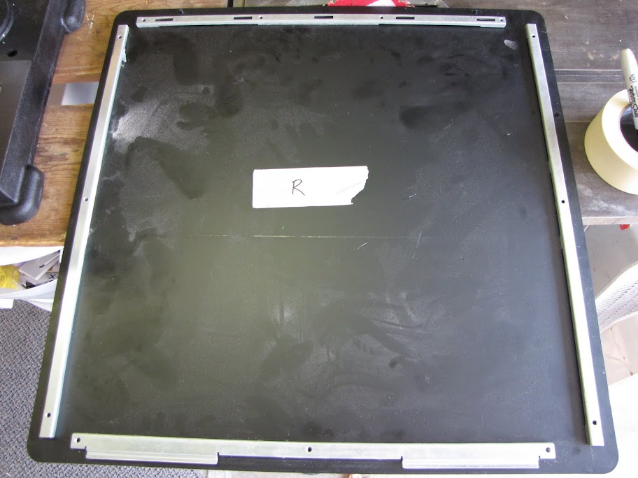
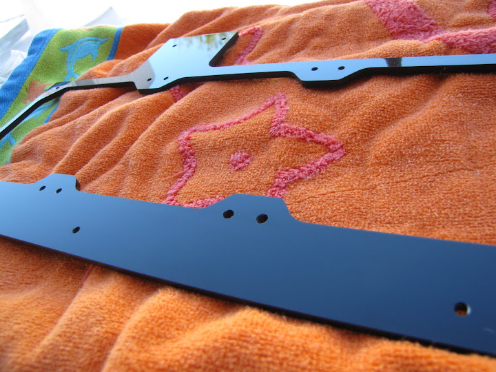
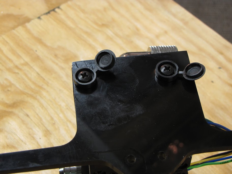
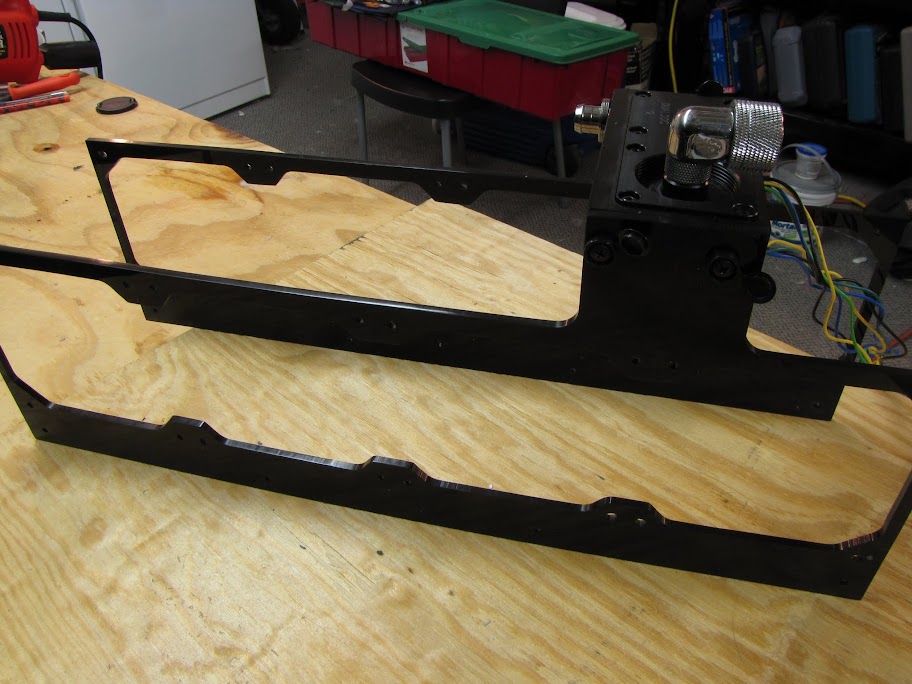
    Step 1. I took off the brackets and labeled the case walls, so I would remember which side is which... and not nearly cut the wrong pattern in the wrong side of the case like I almost did. :o


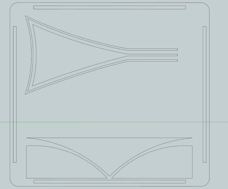
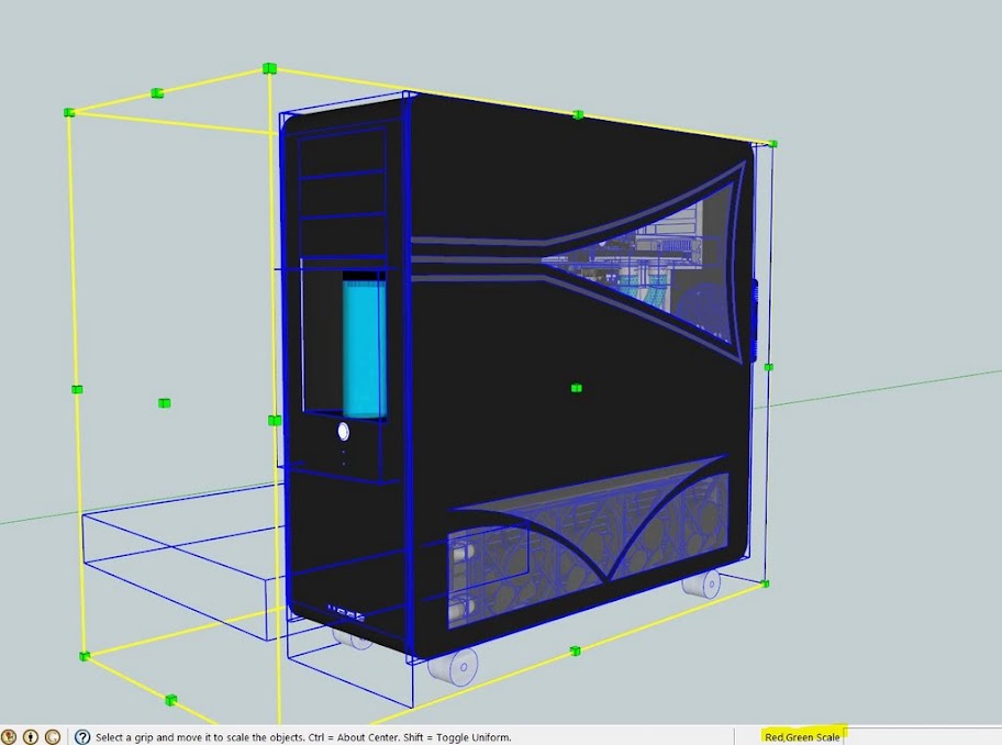
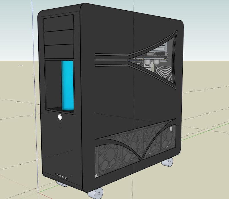
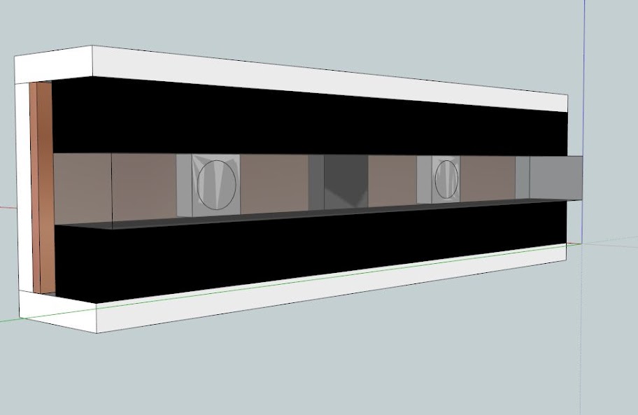
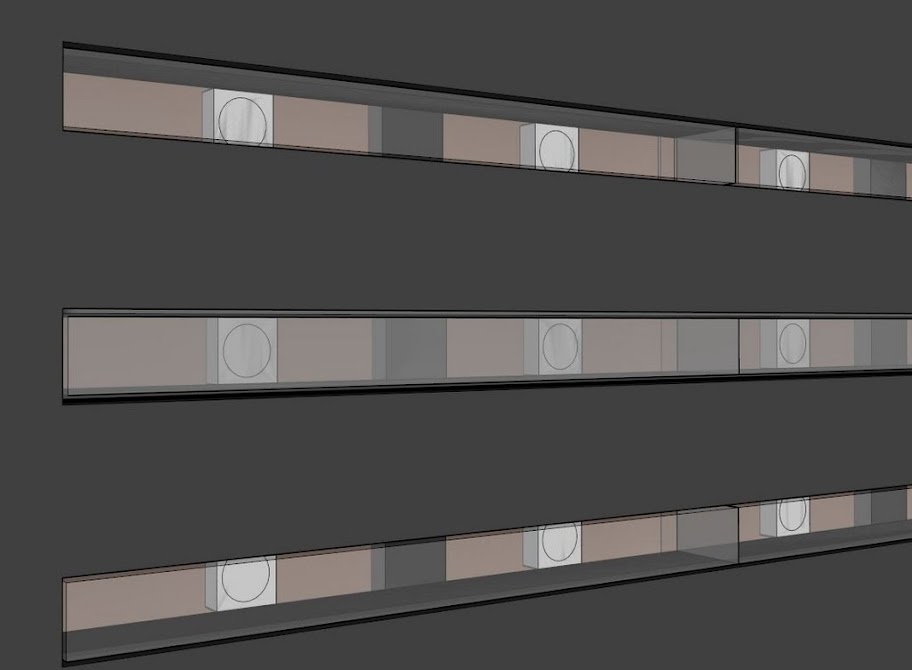
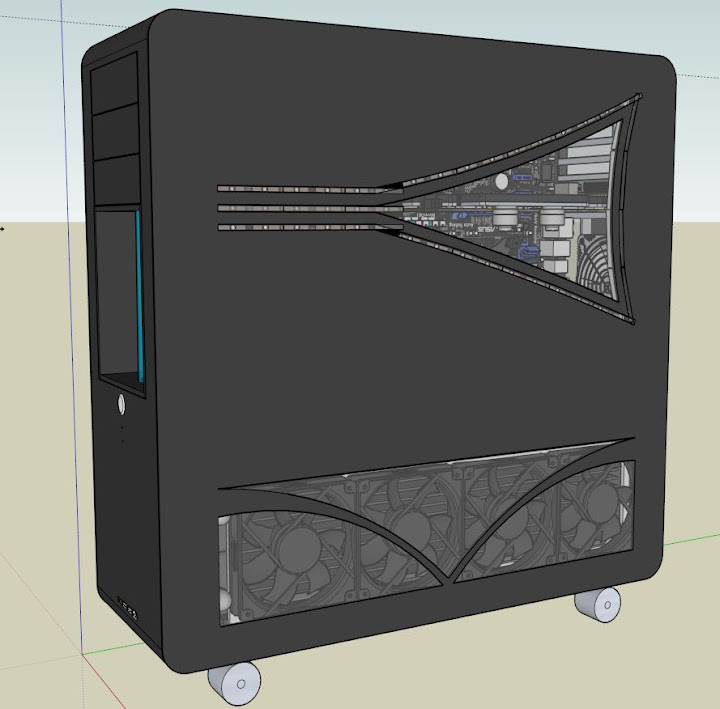
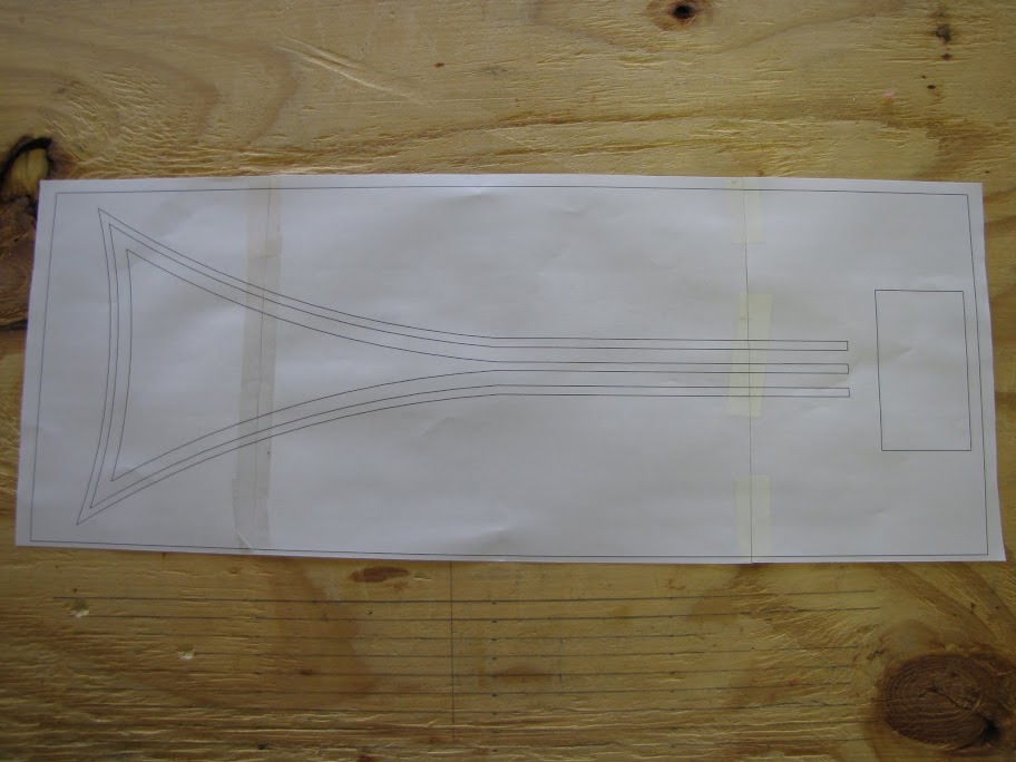
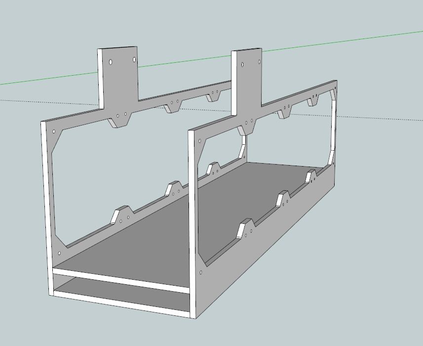
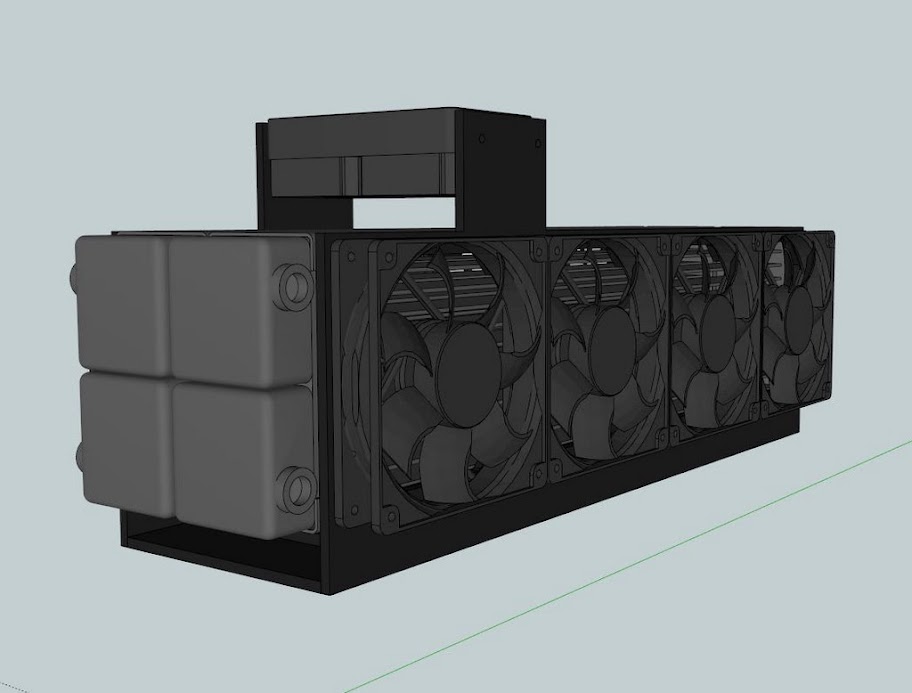
    Step 2. I isolated the first case wall that I wanted to cut in sketchup, turned it BACKWARD (reasoning explained later) and switched the face style to 'wireframe' so that I could see the cuts I wanted to make "through" the design, and turned the perspective off so that I would get strait lines. Then, I set the camera view to "RIGHT" for this particular view and printed the design out.


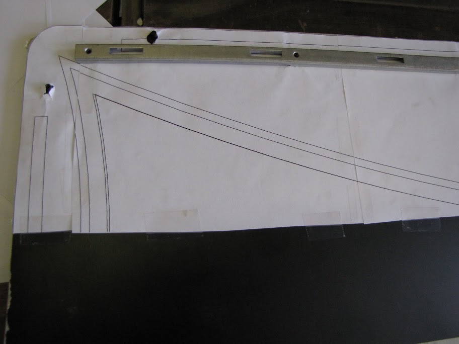
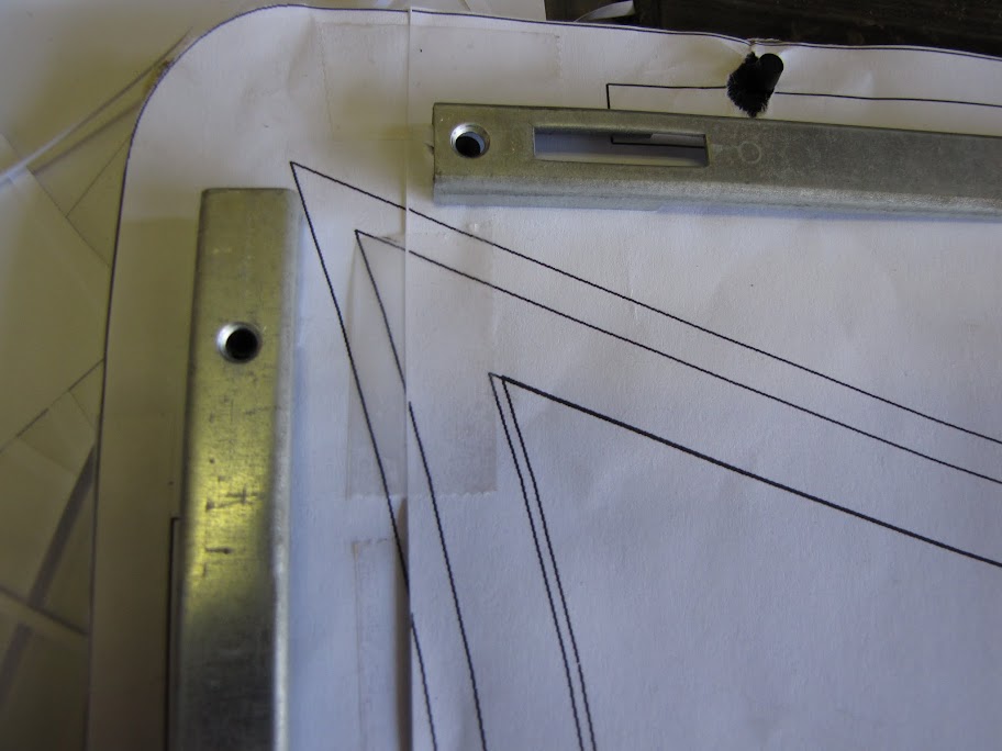
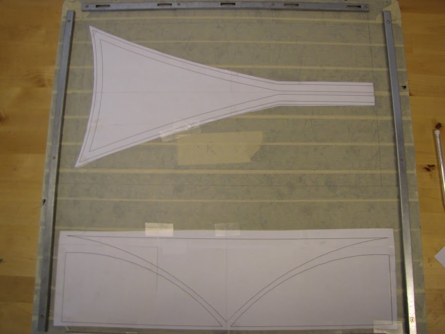
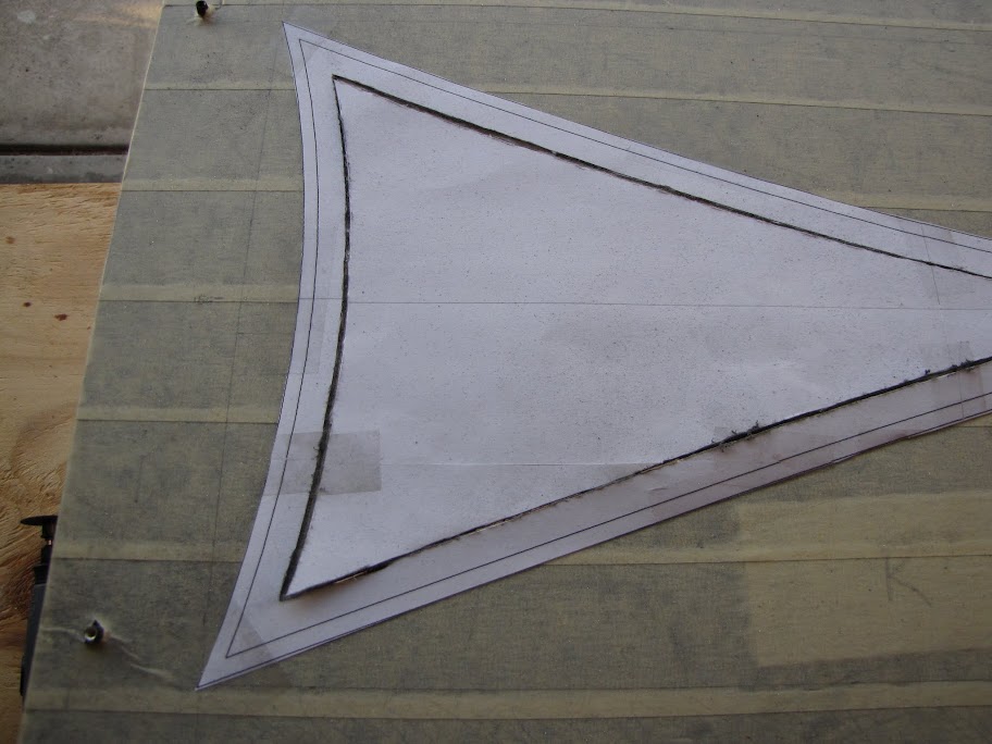
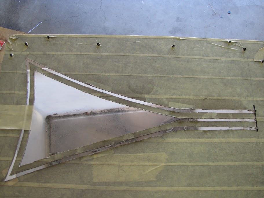
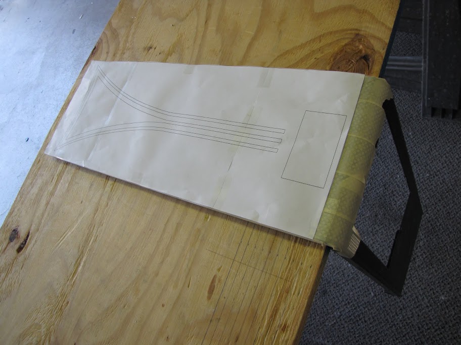
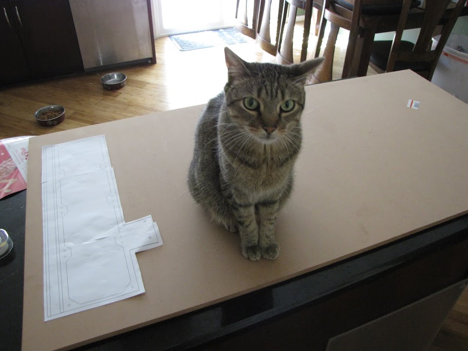
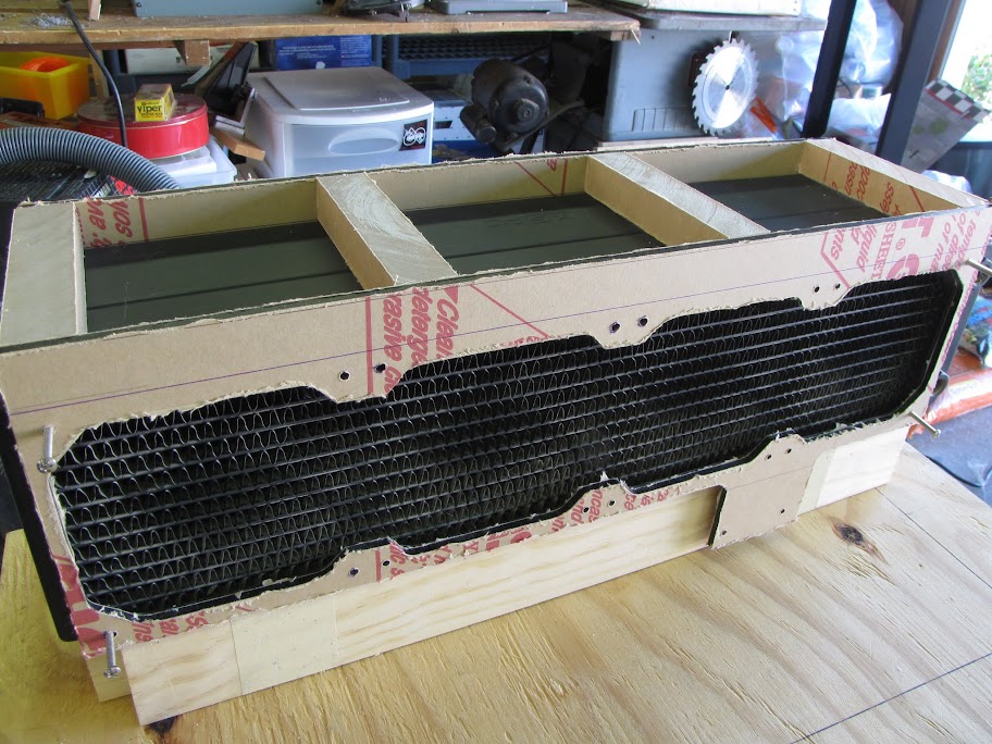
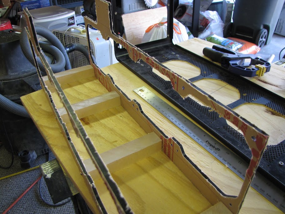
    Step 3. With the design printed out to scale, it of course spanned multiple pages... so I had to do a bit of "arts and crafts" and cut up all the pages / tape them together. As I went, I taped them to the inside part of the case wall. This would serve as my template, showing me where to cut.


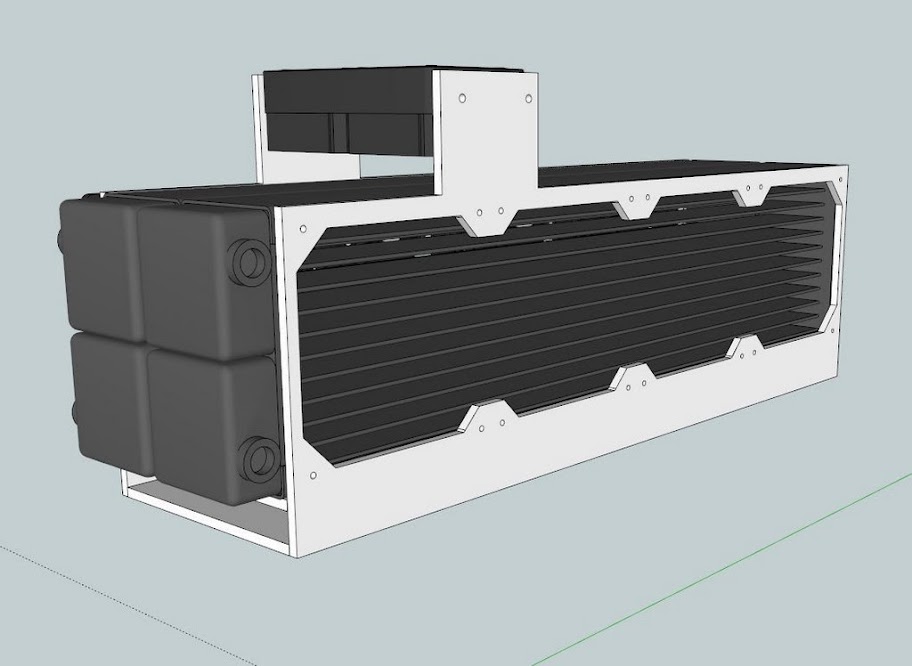
    As I went along taping, I became acutely aware of a problem. The sketchup dimensions were not quite lining up with my case wall! This caused the design to fall behind the supporting braces, which I cannot interfere with...


    A bit of re-measuring confirmed that indeed my sketchup file was not to scale which made me temporarily very sad. Then, I realized it was just a matter of calculating the difference in each dimension as a decimal, and scaling the dimensions of the sketchup to a factor of that calculated dimension. Not too bad!


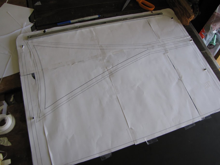
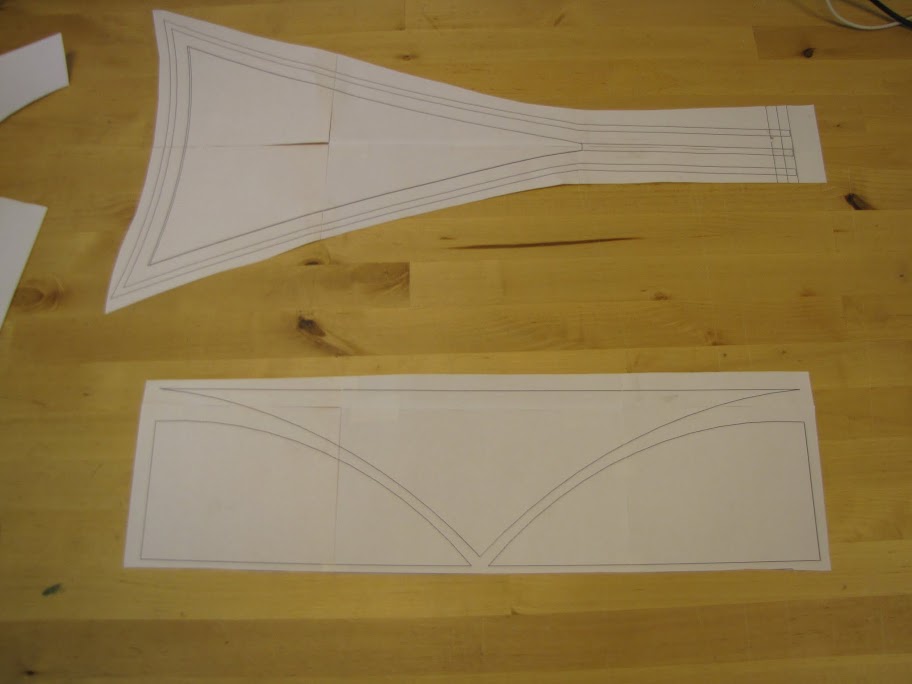
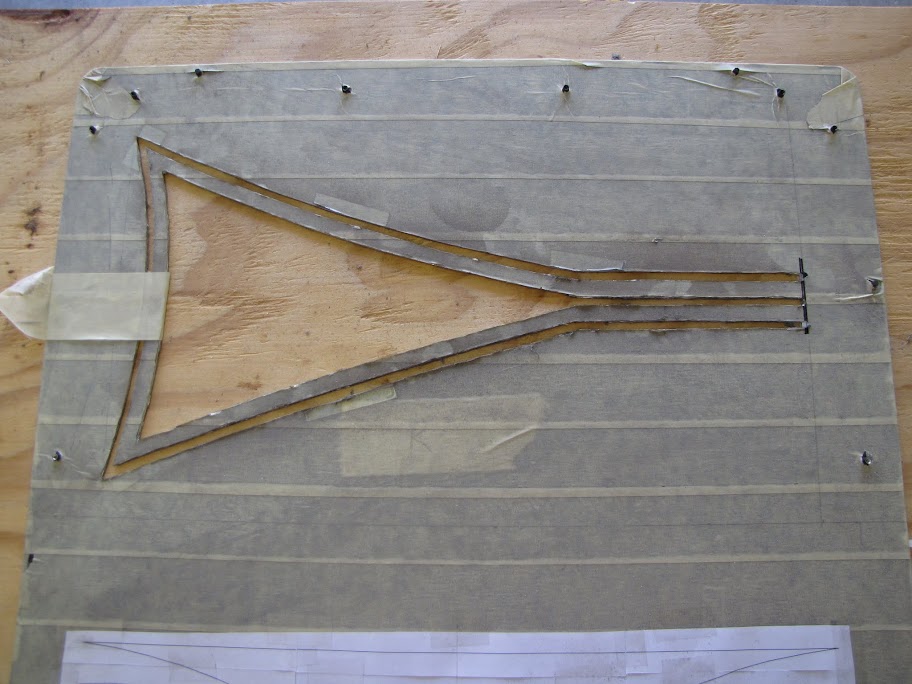
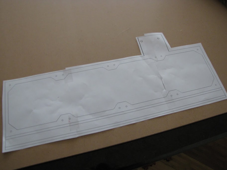
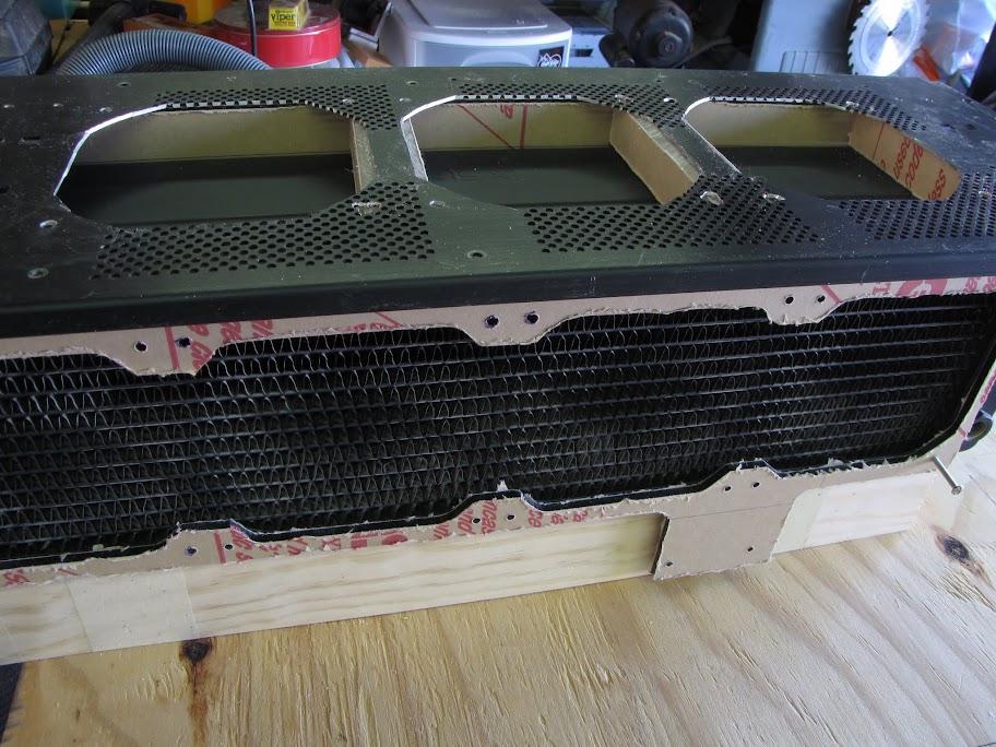
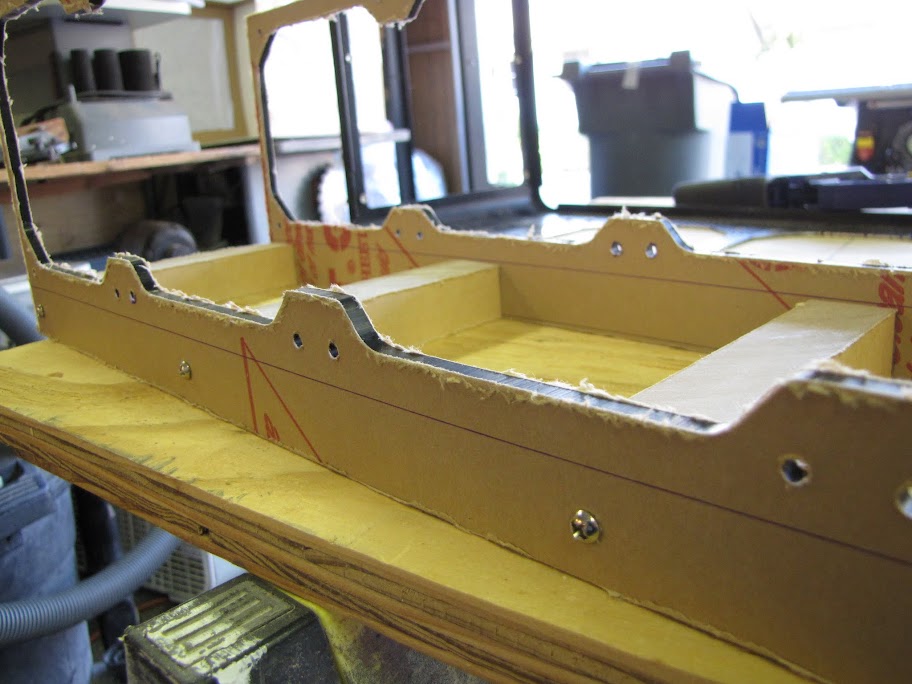
    I noticed that when I selected a grip to resize, I could just type the percentage of size I wanted for each scale, and it would just resize it automatically to that size. Handy! With the sketchup now 'to scale' I re-printed the case wall and went through taping it together again. I lined it up on the case and made some small marks, then cut the pieces out.


    Much better! Things actually... well... fit!

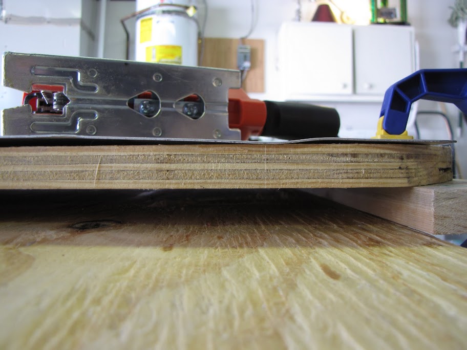
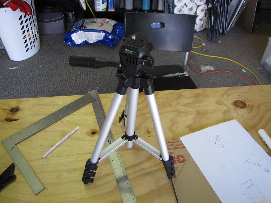
    Step 4. With the design all taped down, it was time to break out the Dremel and start some cutting! I used an old two post server rack I had to serve as a hanging mount for the Dremel and power... I have that nifty cable that extends the Dremel into a much smaller and workable hand tool, so this kept the actual Dremel motor suspended in air where it could stay cool and out of the way.


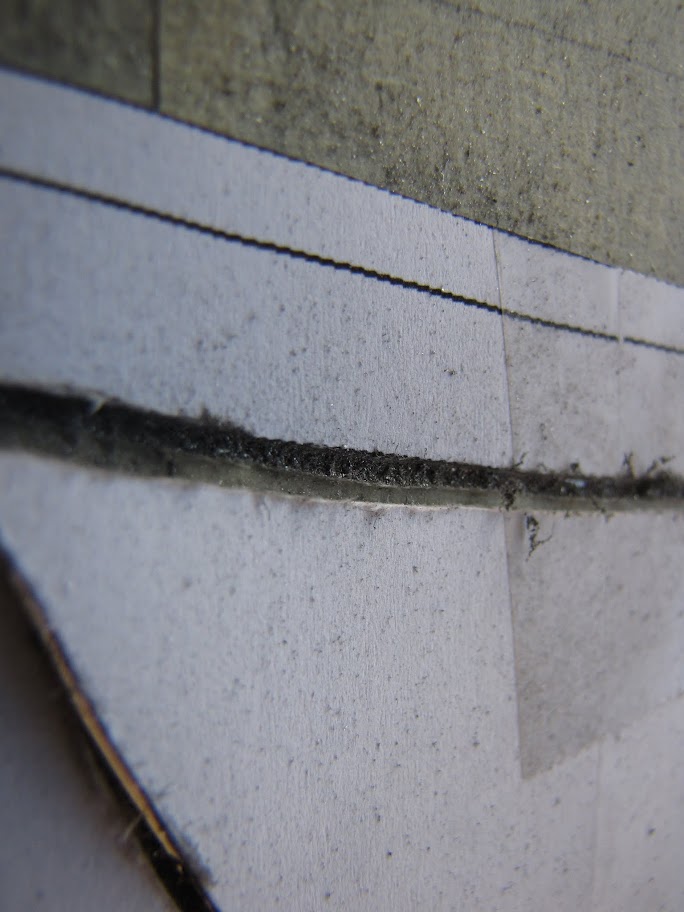
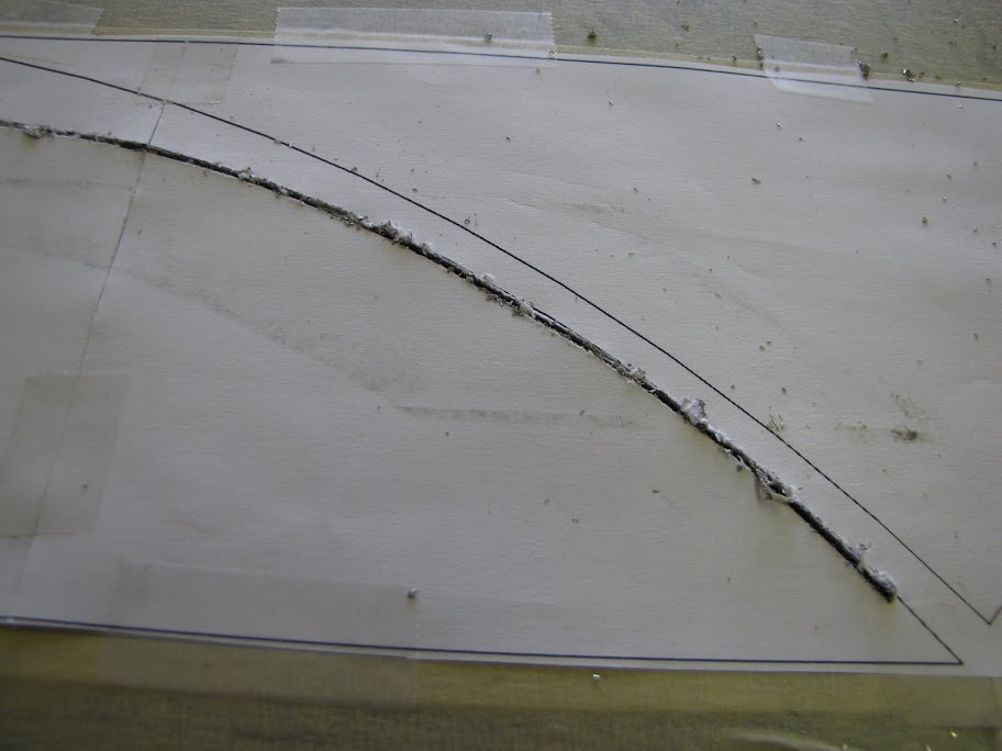
    Much like painting with spray cans, Dremels work best in multiple thin passes. I started with a quick pass... just enough to cut the paper and score the surface, giving a small groove in the case wall to serve as a guide for future passes.


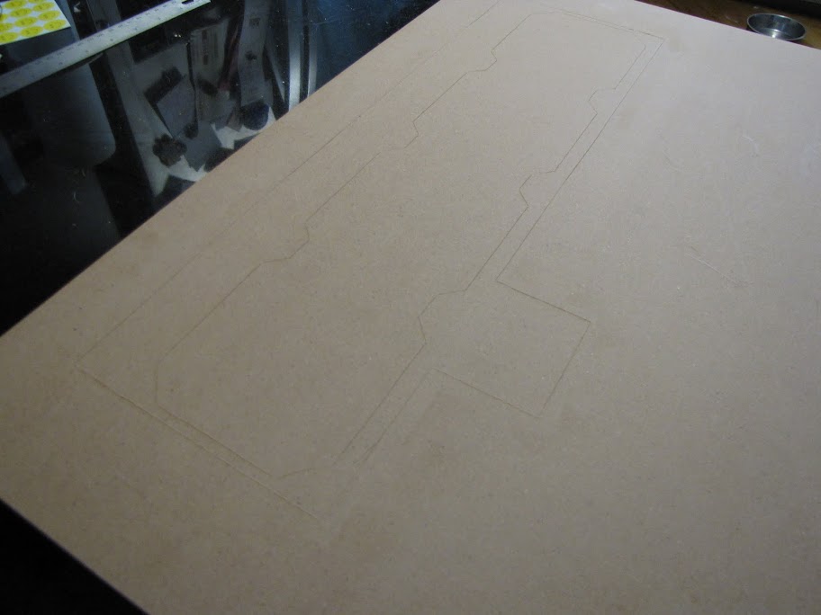
    Step 5. All traced, paper removed. Now for some more serious cutting!


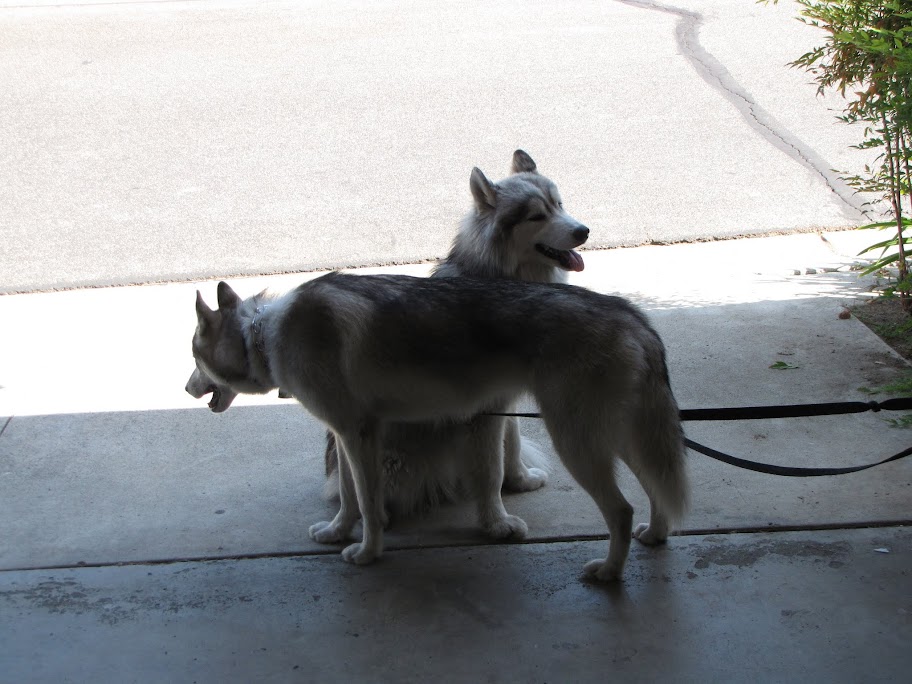
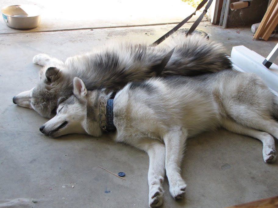
    My support team didn't particularly enjoy the sound of the Dremel... but they were happier out here with me than they were alone in the house, despite the fact that I was right on the other side of the door... so they got to sit in my garage and watch/listen.


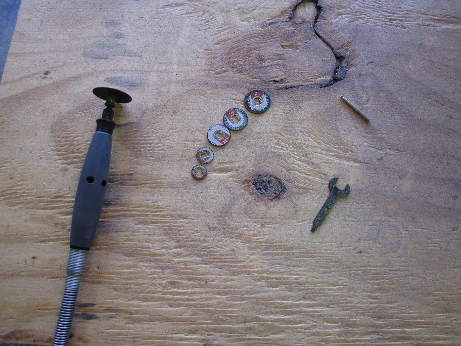
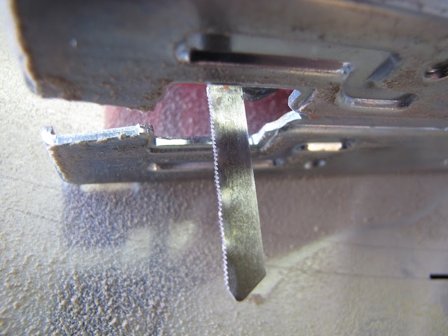
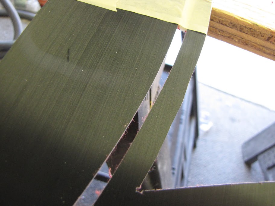
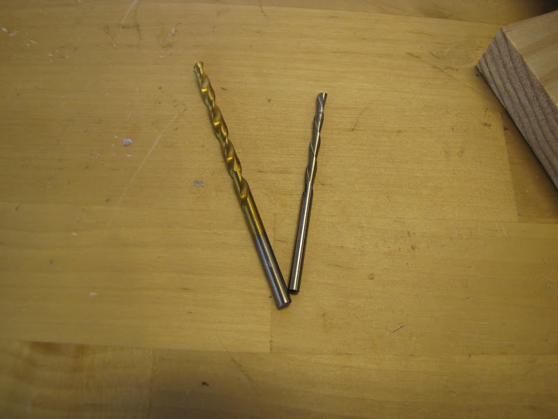
    First pass down... and I was out of disks. The kit only came with one 'regular' metal cutting disk, and all the store had at the time was 'thin cut' metal disks... which worked GREAT for cutting small clean lines as they were only half the thickness of a regular disk... but only lasted like 1/5 as long. I could SEE the disk getting smaller as I used it. I think part of the reason they got chewed up so fast was because my case walls are actually rather thick... about 3mm of solid aluminum. Much thicker than your standard steel case wall anyway.

    The regular disk is the biggest one, the rest were thin cuts... anyway, I tried a different department store and picked up another pack of 5 thin cuts, as well as 5 regular cut disks.


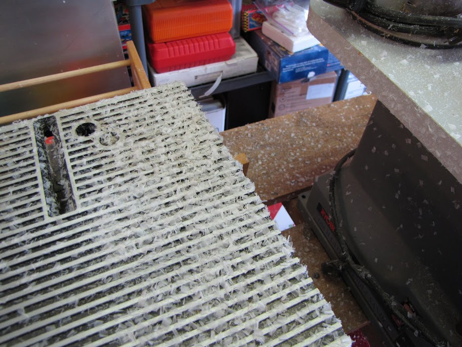
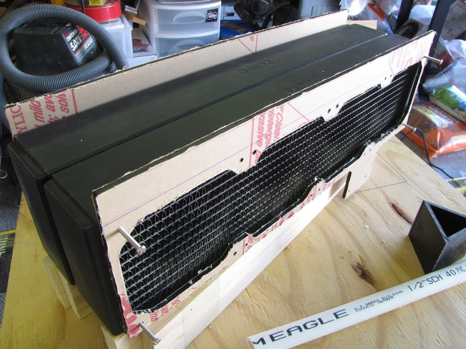
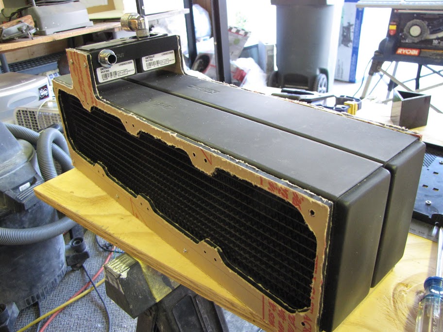
    Anyway... more cutting... and more cutting... finally! All cut out:


    You'll notice I was cutting it over a large bin. That was to keep from damaging the surface I was working on... it also helped the case wall disperse heat a lot better, as it was getting rather hot with all the cutting I was doing. It also helped get the surface up higher, so that I could work while standing comfortably. Important, seeing as it took me like 6 hours of cutting to get this far. :p


    The cuts are obviously still a little rough, too. There is only so much accuracy you can achieve with a rotary tool screaming along at 30k RPM.


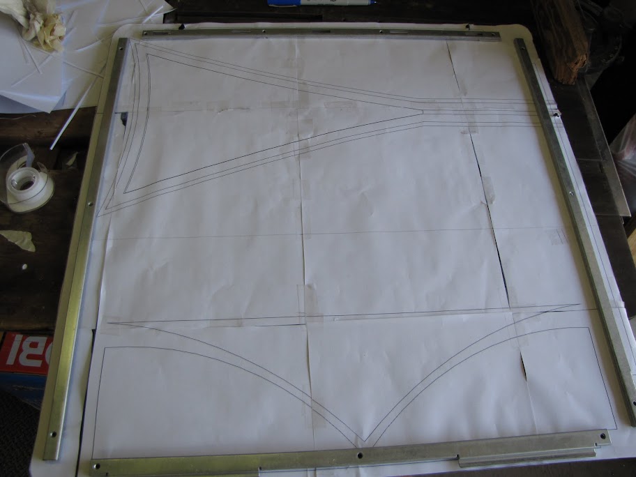
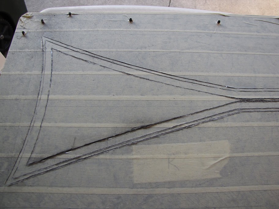
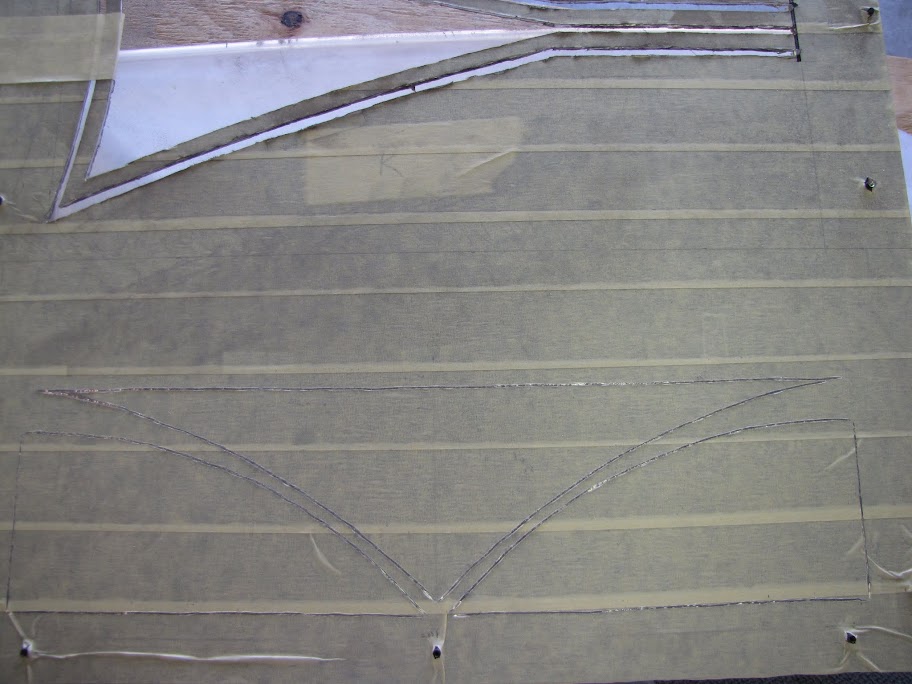
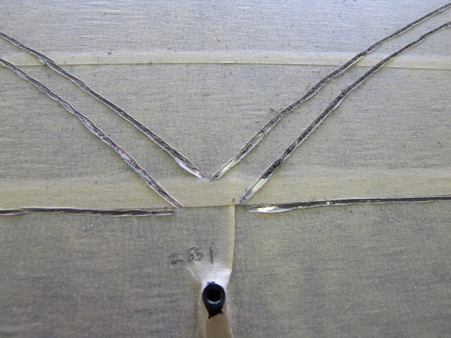
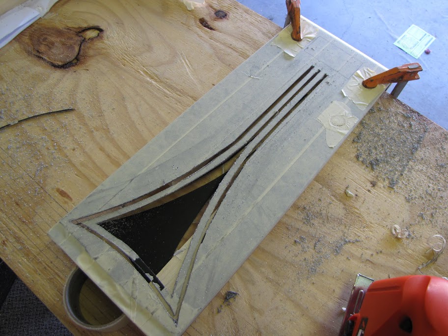
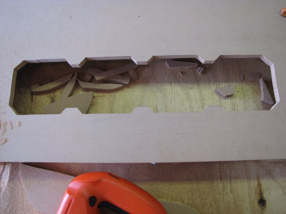
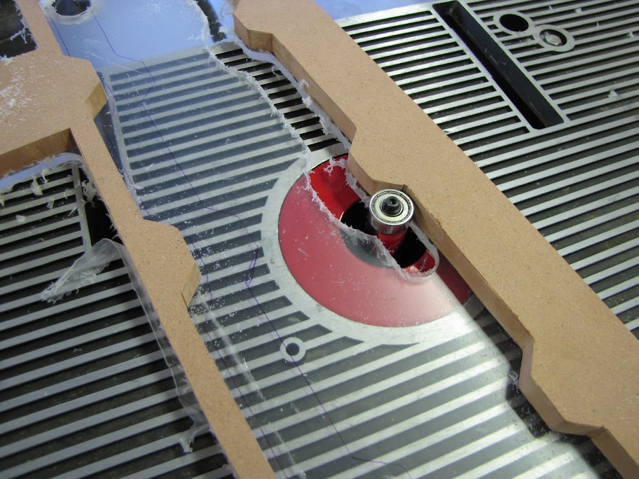
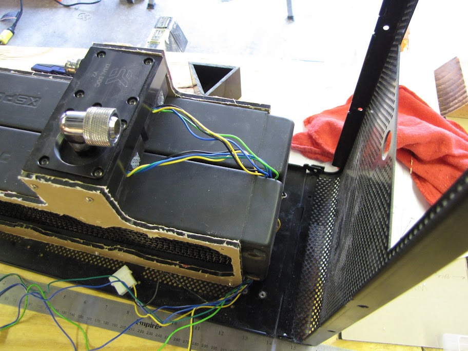
    On to tracing the bottom part, and starting all over! At least this part had only four intricate cuts (the curved lines) so it went quite a bit faster.


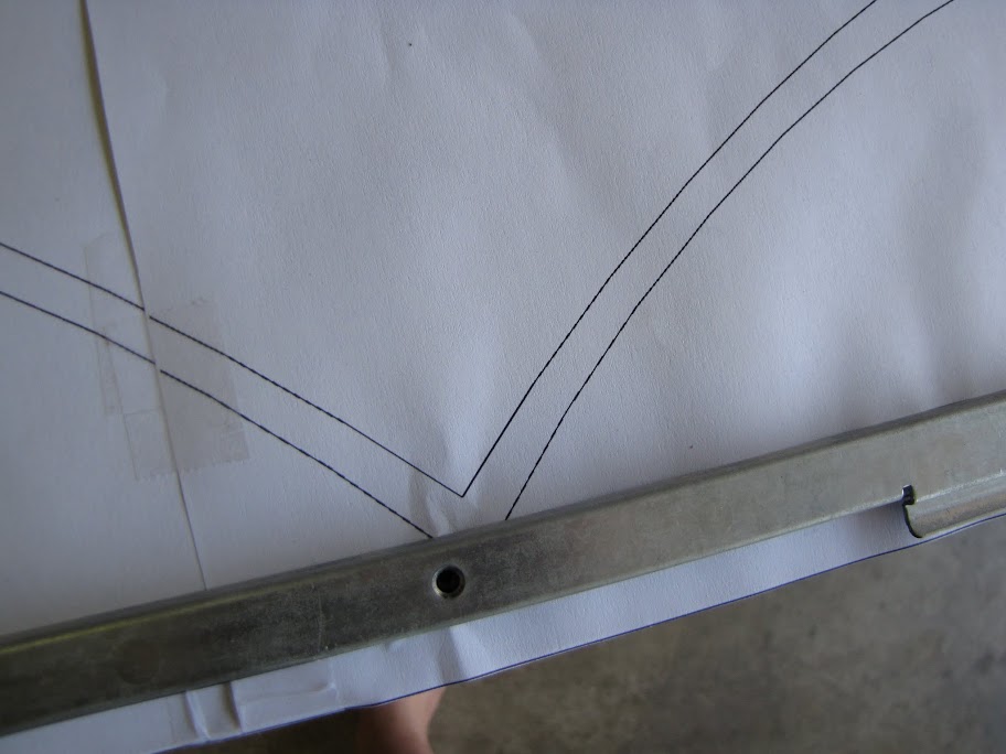
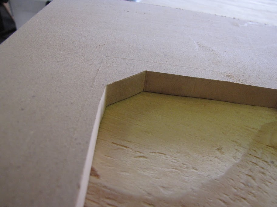
    A little wobbly, but not bad for a free-hand job! I knew this corner part was going to be the most tricky, as it would be somewhat fragile. Also, because the design needed to be a mirror image to remain symmetric, it would be really easy to tell if it was off by even a millimeter.


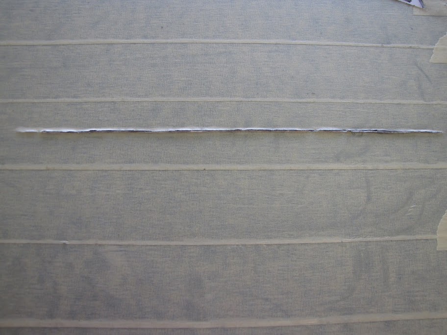
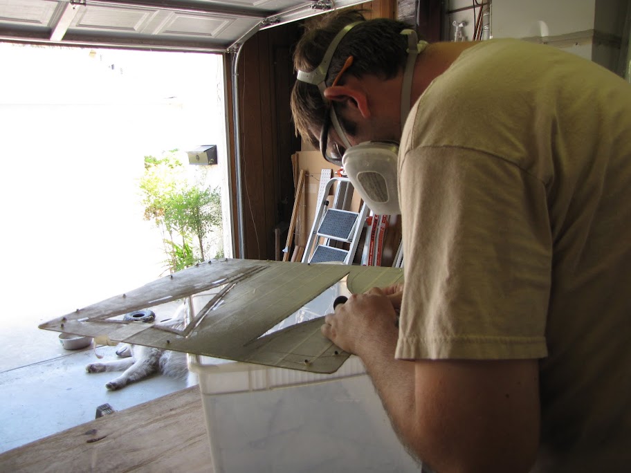
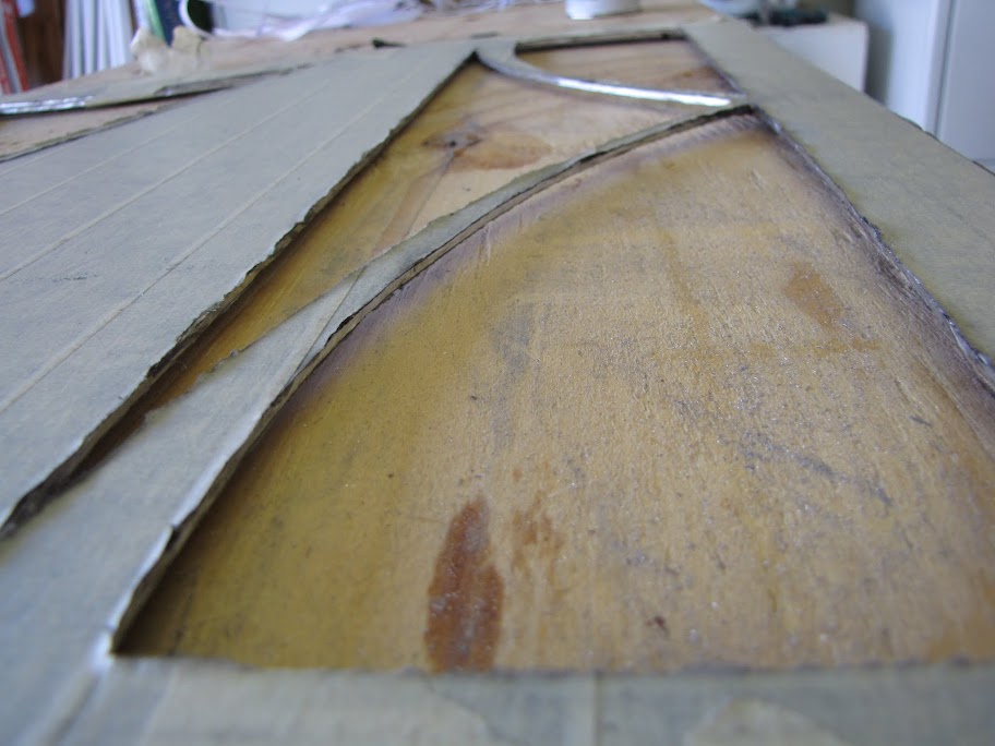
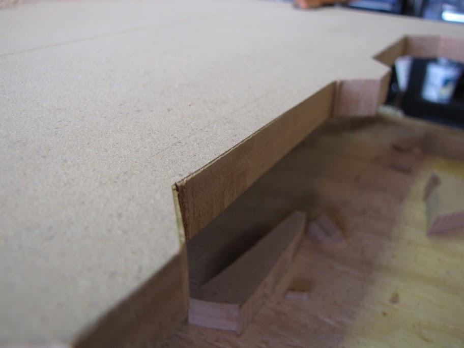
    First pass cutting a strait line free hand along the bottom section... looks actually rather clean from the 'front' side of the case, no? That's the whole reason behind reversing the image, and cutting from the back side. The front side will come out MUCH cleaner, and you will avoid having to repair all the nicks and cuts (not to mention if the Dremel gets caught or skips across the surface, as it often did.)


    Cutting and cutting and cutting... I opted to wear a breather shortly into the whole operation, as I figured inhaling all that aluminum probably wouldn't be a great plan. The goggles are obviously important too!


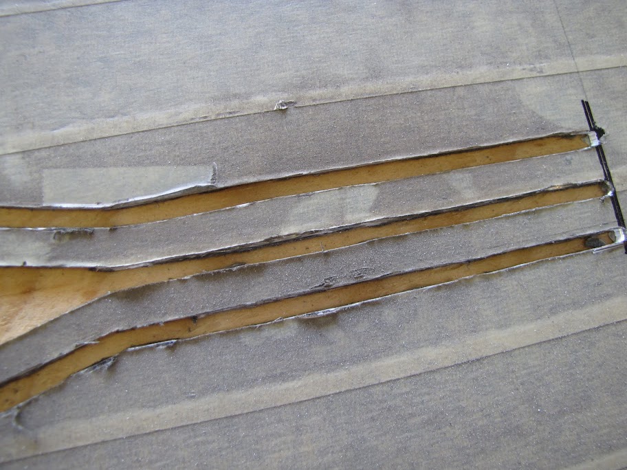
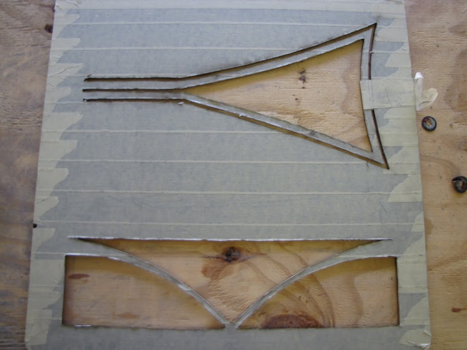
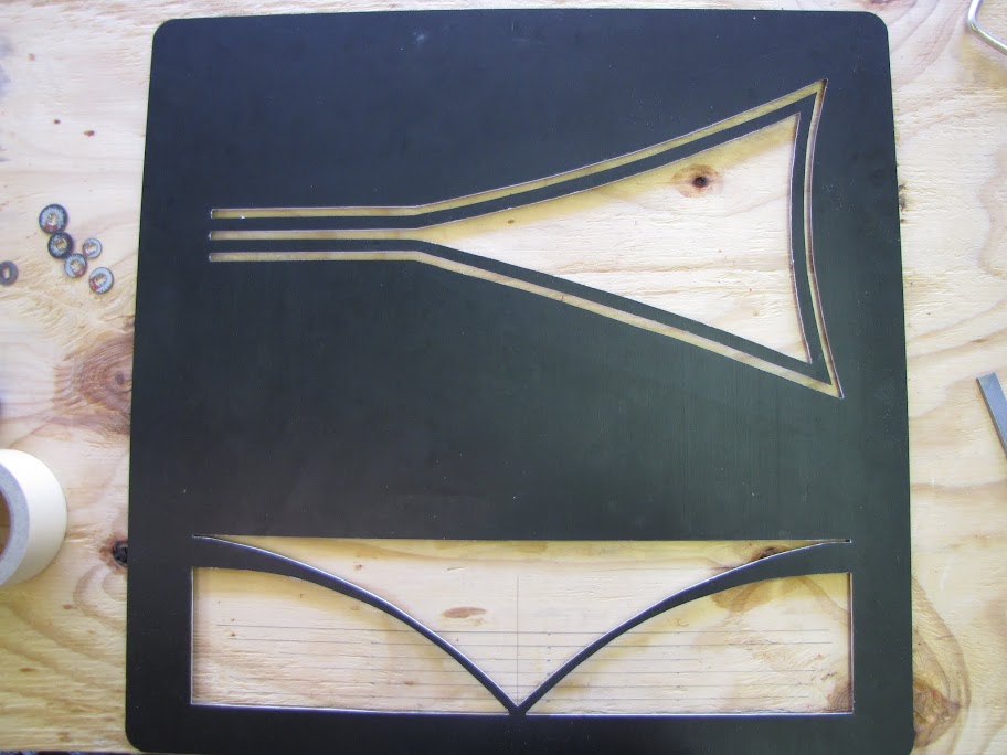
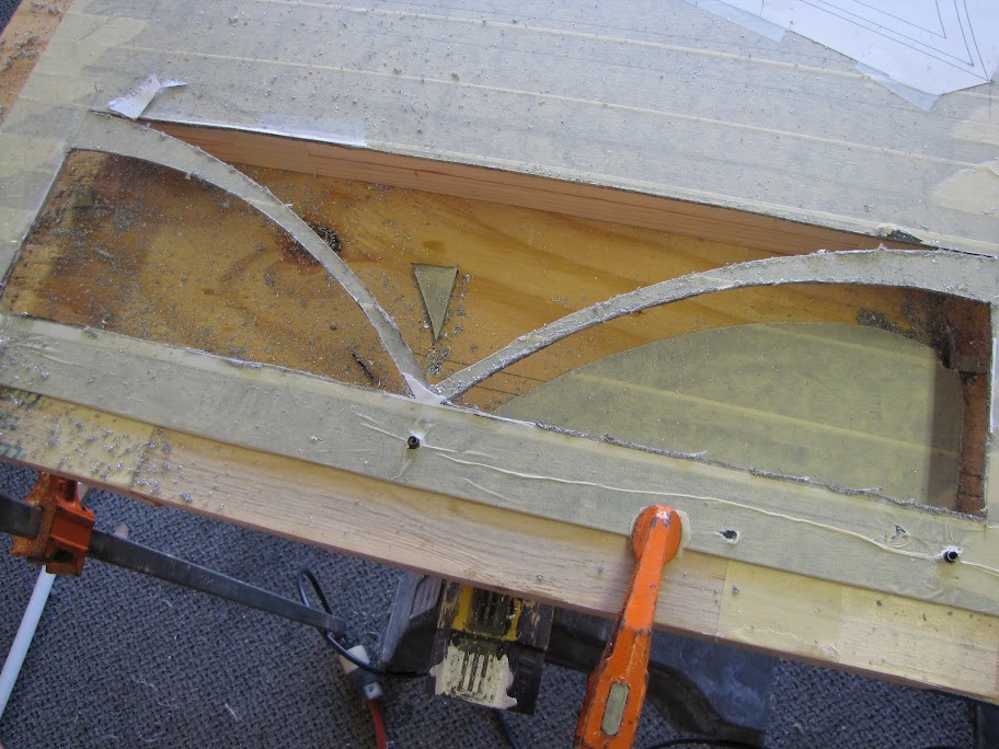
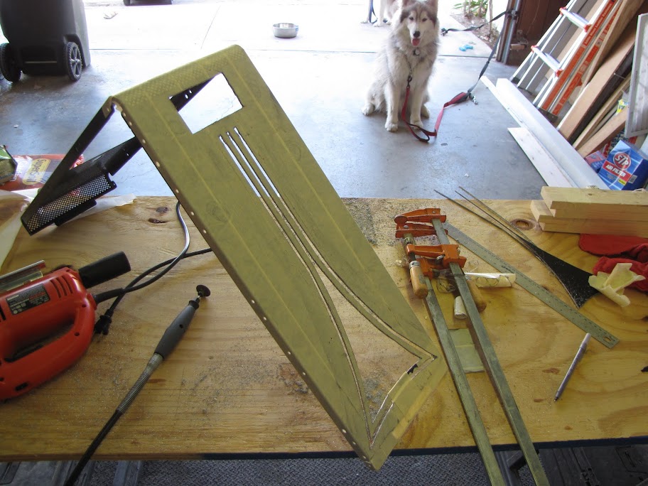
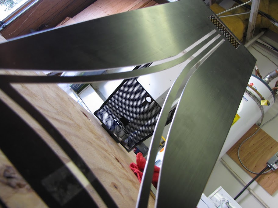
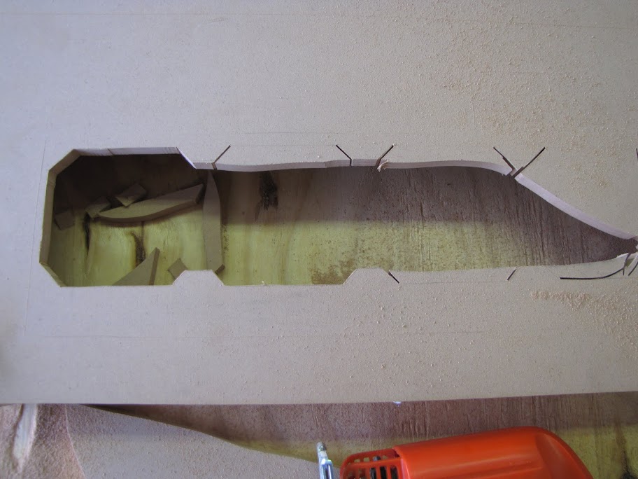
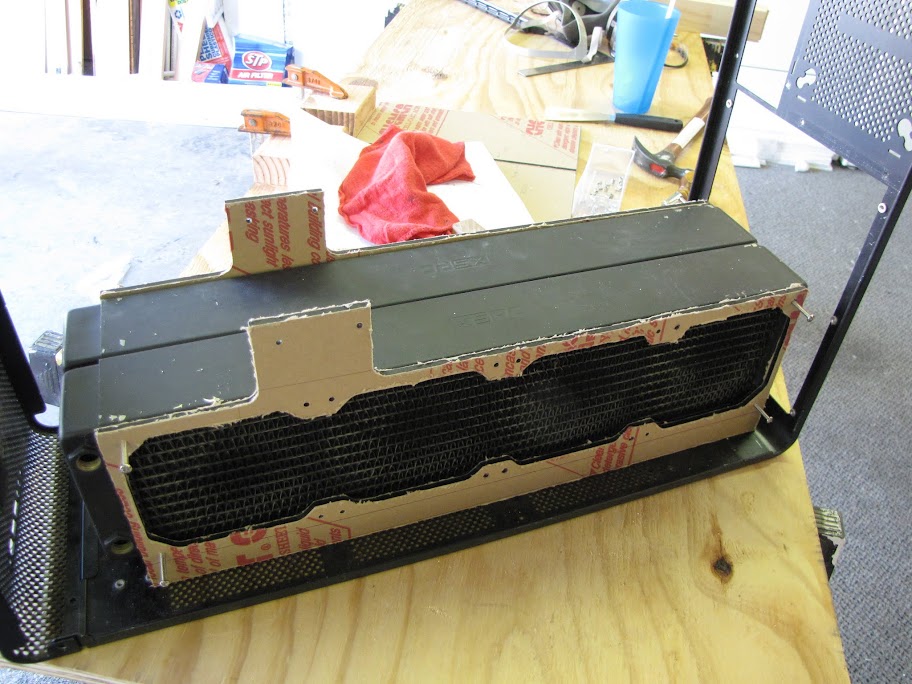
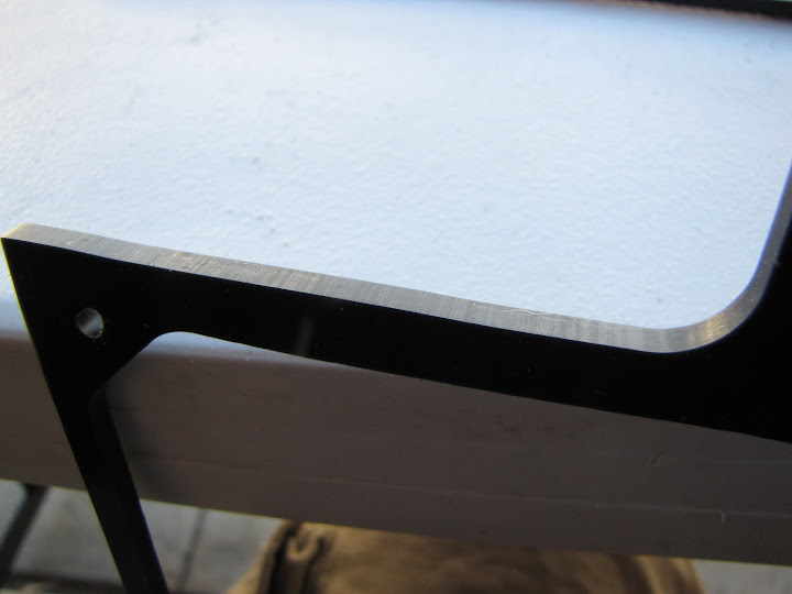
    There we go! All cut out! Rough cutting, complete!


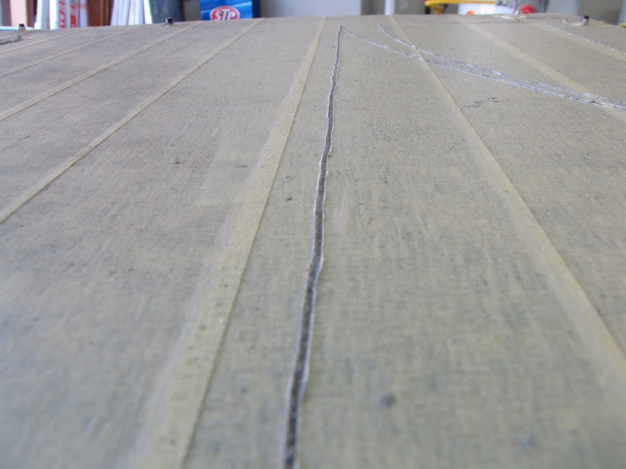
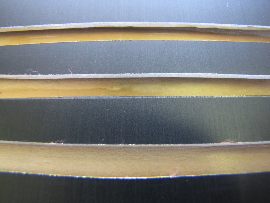
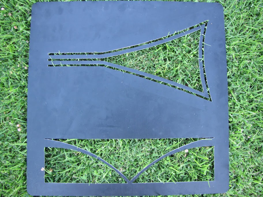
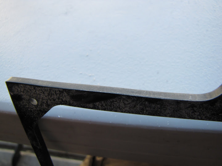
    Step 6. Time to remove all the masking, and see what kind of mess I made!
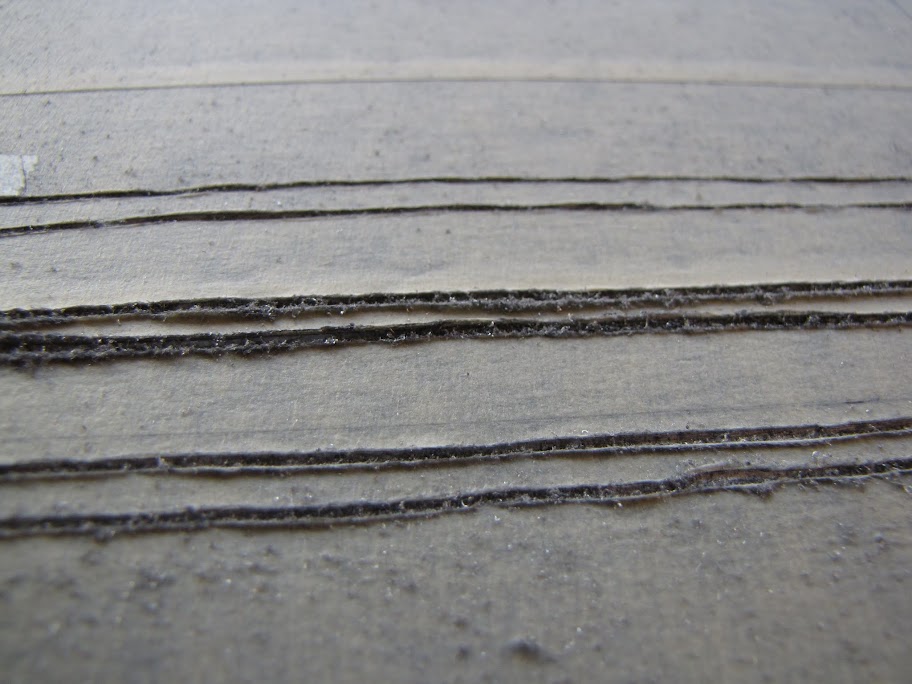
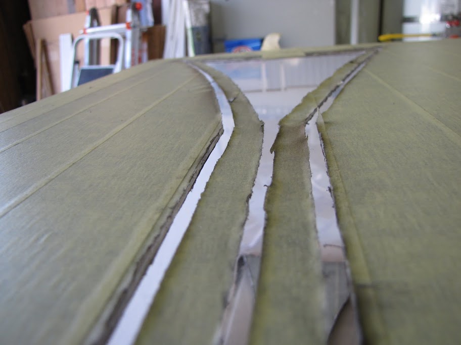
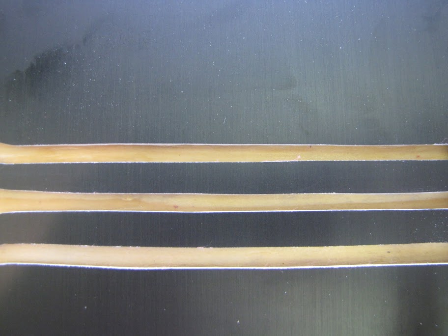
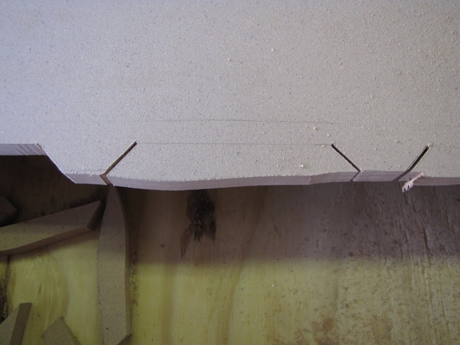
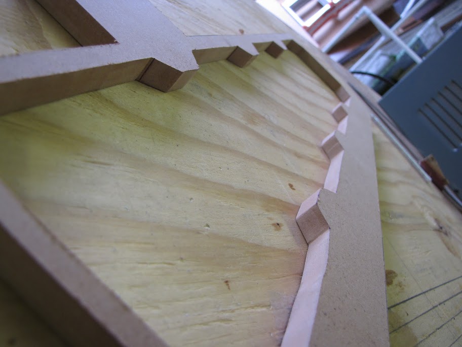
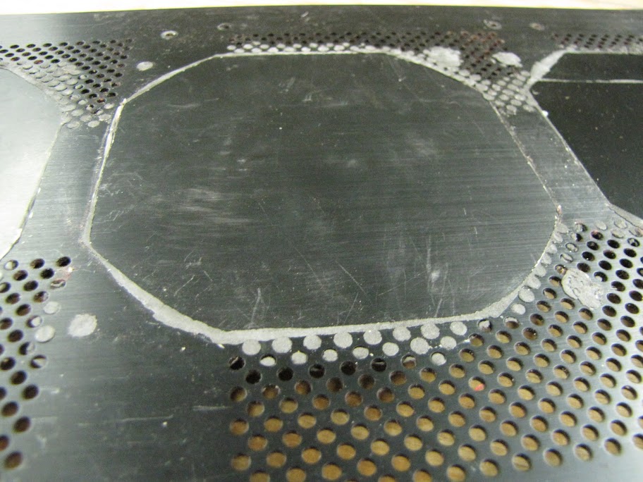


    Pretty wobbly... Especially obvious since there are so many lines so close together. Note, there is a slight "fish eye" effect due to how close I had to get my camera to show the lines... couldn't find a setting to reduce that.

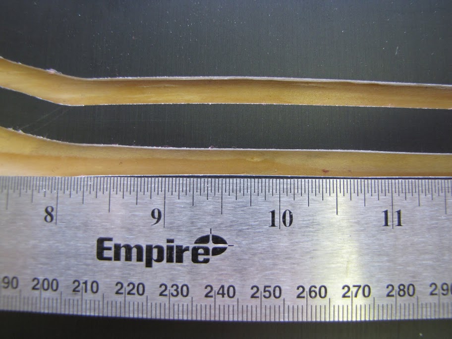
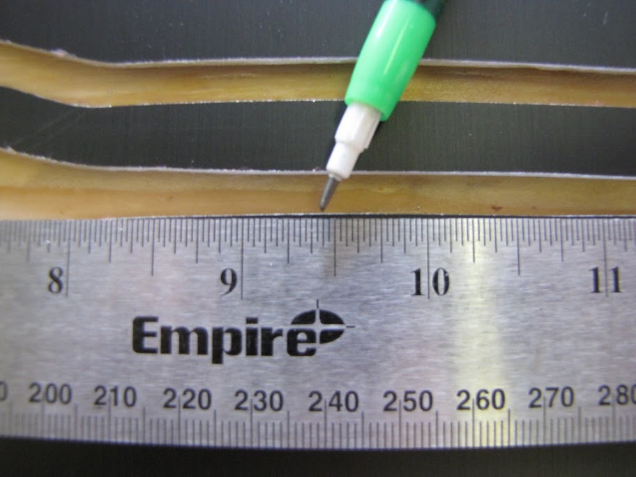
    Hmm... how should I go about making it more strait? How about comparing it to something that is known for being strait? Metal ruler time!


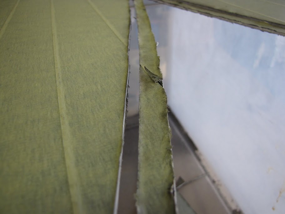
    I found the 'lowest' point in the line, and aligned the ruler with those low points... this exposed the areas that needed a bit more work. Time to mark those areas with a trusty pencil.


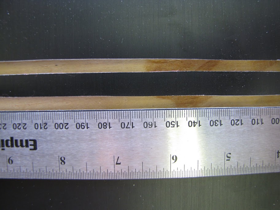
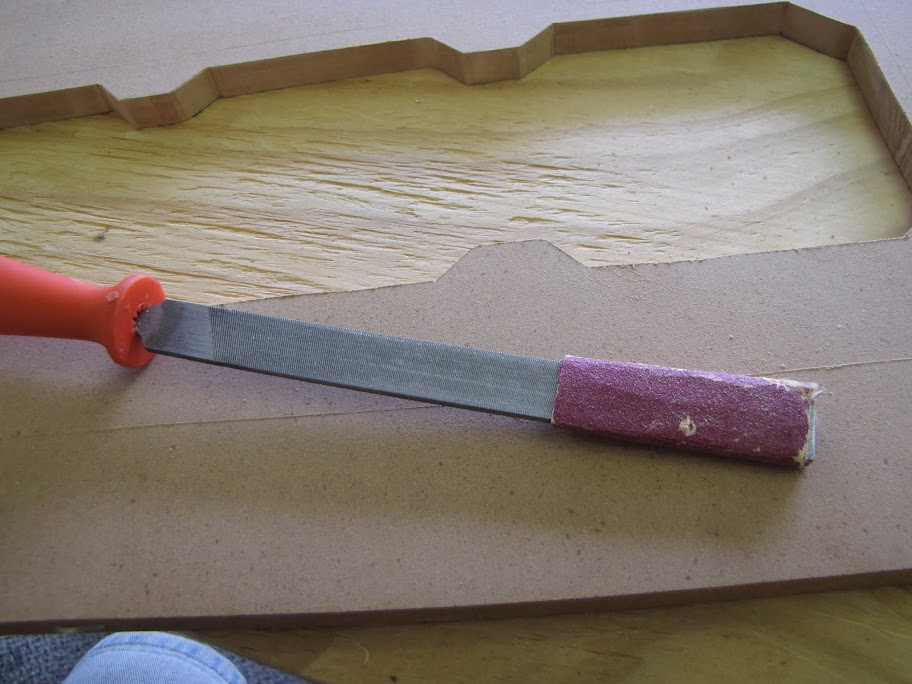
    Step 7. There we are. Defects: exposed. Now time to grind it down with a trusty old hand file! So I started filing... and filing... and filing... man... I am going to gain some serious muscle mass over this much filing! Nerds aren't cut out for this kind of physical activity. :p Anyway, after a few minutes of filing, I ended up with this:


    Much better! Only... a lot more to go. :foot: Filing... Filing... Filing... first small part: done!


    Looking much better! (minus the fish eye lens effect)

    At this point... my spectators were very bored.


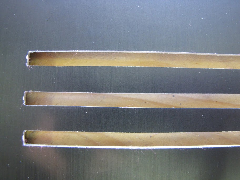
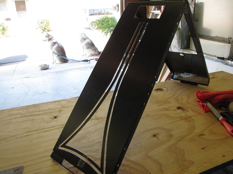
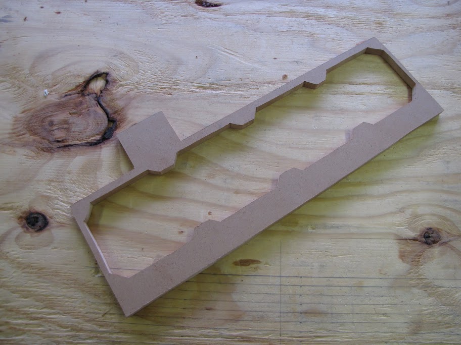
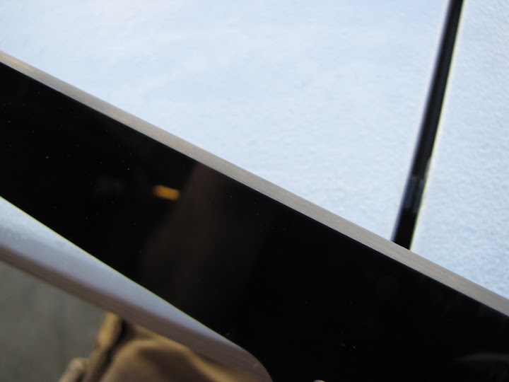
    Finally! Done filing!


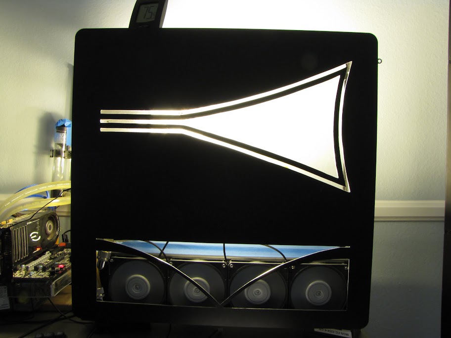
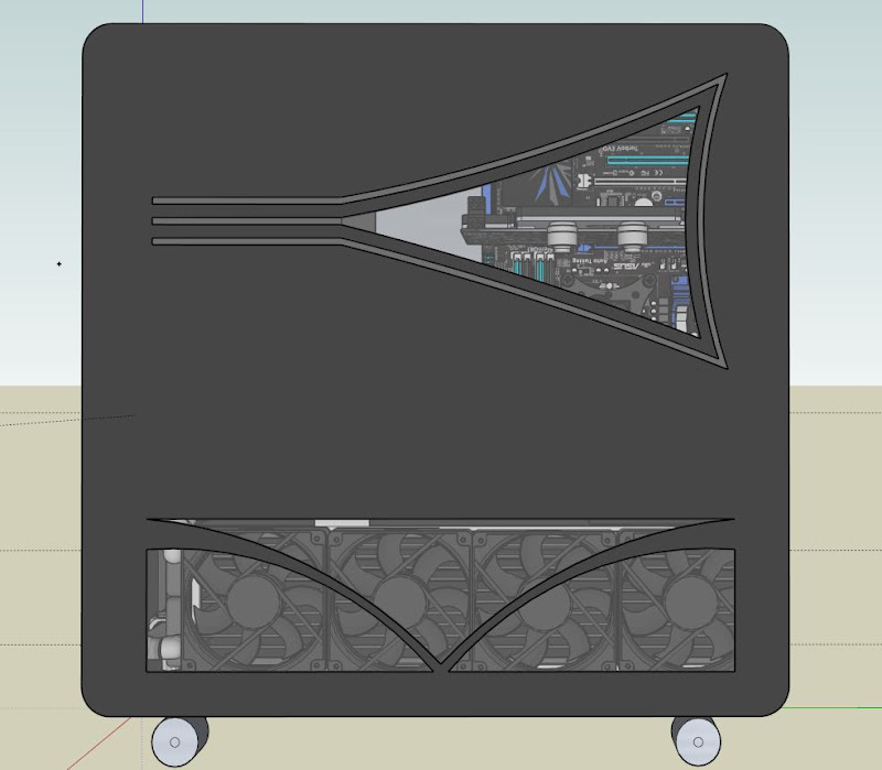
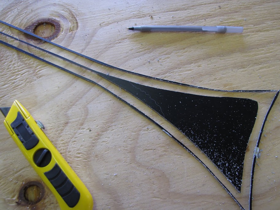
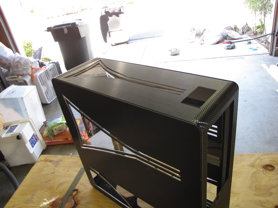
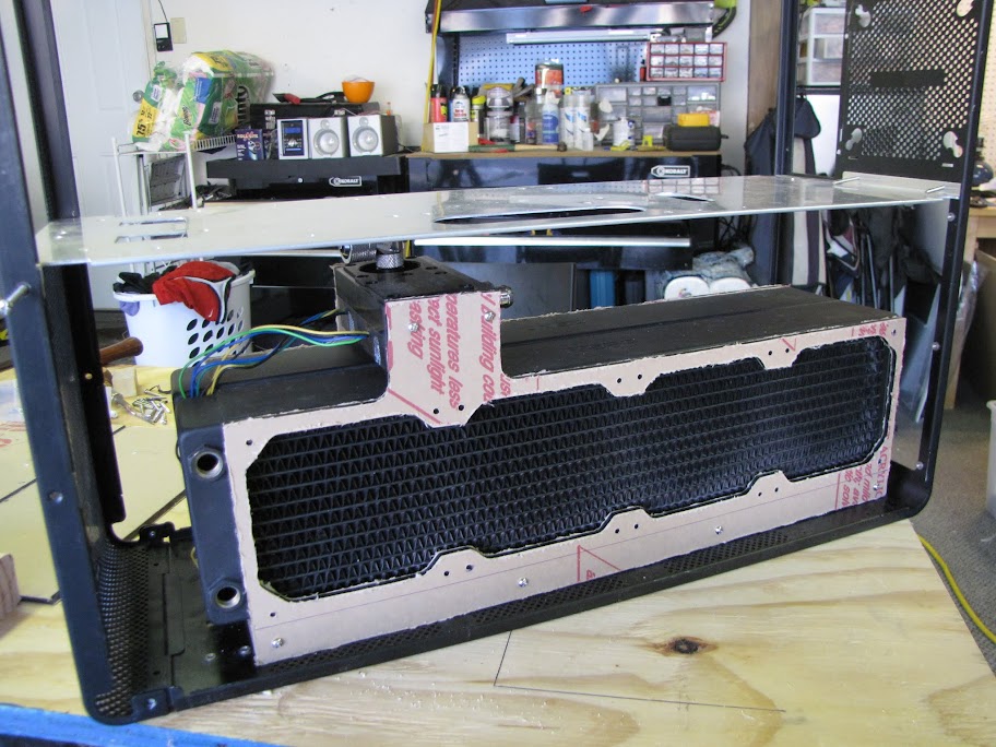
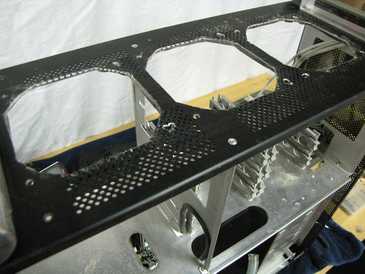
    And here's how it looks (roughly) on the system. Note, I'll be putting mesh in the bottom area, and the thin lines will be filled with acrylic.


    Hope you enjoyed the process! It was quite an adventure for my first time really digging into a case mod like this. I'm pretty happy with how the design came out, and I think it will look even better when I get the acrylic lines figured out and filled in. I did some work on that as well this weekend... but I think I'll save sharing it for when I have something more presentable.

    Thanks all! And as always, feel free to comment on any ways I can improve the process or the results! I of course have the other case wall, and the front/top of the case still left to do! :p
    EVGA z77 FTW -- 16GB of Samsung MV-3V4G3D/US -- Intel Core i7-3770k -- EVGA GTX680 -- Corsair AX850 PSU -- Lian-Li PC-v2000b -- 2x XSPC RX480 Rads -- EK-RES-250 -- EK-DDC Dual Top/pumps -- EK-FC680EN Full Cover block -- Swiftech Apogee HD Block

  2. #52
    Xtreme Addict
    Join Date
    Jan 2008
    Location
    Bonnie Scotland / Sunny England
    Posts
    1,363
    Very nice. Love the pups also!
    PROJECT :: The Xtreme (WET) Dream!!!

    PERSONAL H2O BESTS :
    E8600 @ 4.8GHz
    E6750 @ 4GHz QX9650 @ 4.6GHz
    i7 920 @ 4.6GHz

    PERSONAL AIR BESTS :
    Sempron140 @ 4Ghz (Stock Cooler)
    i7 3960x @ 5.4ghz (Air Cooler)

    Bex : "Who said girls can't play PC games or overclock!? Do I look like your imagination!?"
    Aaron : "TBH, a girl doing all that is a pretty perfect girl!"
    Swift_Wraith : "could someone please check bex for a penis?"

  3. #53
    Registered User
    Join Date
    May 2012
    Location
    California
    Posts
    96
    Hello Everyone!

    I had hoped to do some more cutting on the other case wall this weekend... but it was waaayyy too hot outside... so I spent some time designing and planning the innards of my build this weekend instead! I spent a ton of time in sketchup... a good portion of which was spent rebuilding from scratch to get the system properly to scale (and fix some errors I made early on due to my relative inexperience with sketchup... ). I also spent some time putting pieces 'physically' together (like assembling my pump combo and drain system)... but I don't really have any pictures worth sharing of that quite yet. Finally, I finished the second (and more 'scientific') set of radiator tests, and came up with significantly different results!

    This pass through, I used air and water temperature monitoring tools that were accurate to a tenth of a degree (instead of a lousy two degree resolution, with an error margin of 2 degrees... ) and took twice as many samples for a better average. Long story short, the FAN > RADIATOR-RADIATOR > FAN orientation ended up being the best of the three tested... so that's what I am going with! It's actually fortunate that this orientation won, as it gives me a bit more room to play with... having a bevel in the middle and trying to give more air space was very difficult for this size of case.

    Anyway, here's where I am in sketchup now!


    This first shot is an overview... lots of stuff going on here that is new. For starters, I redid the loop order to cut down on clutter somewhat. I think this is the most efficient way it can be done with the space that I have right now... but I'll keep thinking on it. I wanted to avoid tubes 'crossing' as much as possible, because it looks cleaner to me that way...

    I also added some acrylic parts around the radiator... I am planning on making a "U" shaped bracket for both radiators to sit in, and the fan screws will go through the acrylic into the radiator, holding the whole business together. This will also give me a place where I can connect the pump to, as it works out that the pump is almost exactly as wide as these two radiators back-to-back.


    I plan on putting some gaskets or something between the acrylic and the pump to help cut down on vibration. It's not very obvious from this shot... but the pumps are suspended over the radiators by about 10mm... that should give it a little airflow, as I understand these pumps can get fairly warm when running at full speed. I took a serious look at grabbing some of those koolance heatsink replacement pump bottoms, but determined I couldn't quite get them to fit in this area unfortunately... they look real nice...


    I also rebuilt the drain system in sketchup, after finding that the 5-way block model I found online was not to scale either... :facepalm: I scaled the model to make it accurate, but couldn't figure out how to return the g1/4 ports to scale without seriously messing up the model... so that's why they look a little weird. Oh well. :p I opted to go with G1/4 extenders instead of tubing here, as the runs were pretty short. I also plan on using a "D Plug" for connecting the drain to the 5-way, so that I could easily remove the radiator from the case to clean it (after it's drained, of course.) One of the caps on top will probably be a thermal sensor, too.


    I've also been toying with the idea of using a "half hexagon" shape to house the front reservoir, rather than the "half cylinder" shape I was using before. I think it plays a little better with the 'angular' features of my case, and it's a heck of a lot easier to fabricate, too.


    This area (the return from the radiators to the reservoir) is a little tight, too. I will have to buy a 30 and 60 degree angle fitting on each end, in addition to using a 90 degree and two compression fittings. I like the tubing in my system (I prefer it over long runs of extenders, anyway), so I think this is the way I will go... but I am not positive yet.


    And here's a few shots of the case all put together as of tonight. Coming together! I still have to do the designs on the front of the case... but that's next!


    Thanks everyone!
    EVGA z77 FTW -- 16GB of Samsung MV-3V4G3D/US -- Intel Core i7-3770k -- EVGA GTX680 -- Corsair AX850 PSU -- Lian-Li PC-v2000b -- 2x XSPC RX480 Rads -- EK-RES-250 -- EK-DDC Dual Top/pumps -- EK-FC680EN Full Cover block -- Swiftech Apogee HD Block

  4. #54
    Registered User
    Join Date
    May 2012
    Location
    California
    Posts
    96
    Quote Originally Posted by RCG_Bex View Post
    Very nice. Love the pups also!
    Thanks!

    I see (from your signature) that you have a Lian-Li build of your own going on... and people told me that I had too much radiator in MY build!

    Looks great though, I'm jealous!
    EVGA z77 FTW -- 16GB of Samsung MV-3V4G3D/US -- Intel Core i7-3770k -- EVGA GTX680 -- Corsair AX850 PSU -- Lian-Li PC-v2000b -- 2x XSPC RX480 Rads -- EK-RES-250 -- EK-DDC Dual Top/pumps -- EK-FC680EN Full Cover block -- Swiftech Apogee HD Block

  5. #55
    Registered User
    Join Date
    May 2012
    Location
    California
    Posts
    96
    Short posting before I delve into what will hopefully be an eventful weekend! I've been doing some sketchup work on just how I would like to build housing for my LED strips so that I can attach them to the sides of the case. Anyway, the design is still a little rough in sketchup... I couldn't find a good way to 'bend' segments with an even gradient to fit into the curves of the case... but it should be easier to do 'physically' with a heat gun and some liberal pressure. Here's what it looks like so far...

    First of all, here's the LED strip I will be using. It's pretty cool stuff... each LED is a tri-color individually addressable light compatible with PWM, meaning I can control the color and pattern of each individual light to make some pretty nuts patterns.


    The other nice thing about this strip is that I can cut it every two LED's, so I can customize the length pretty easily to fit what I need.

    I started on paper designing the housing to fit one segment, and quickly moved to sketchup. Here's the component I created from scratch to represent the LED strip and it's Acrylic housing:


    Basically, I plan on using a strip of 'EndLighten' acrylic that is supposed to distribute light really well. That strip (shown transparent above) will be sandwiched by two opaque black pieces of acrylic to help 'keep the light in' so to speak. To the back of this stack, I will adhere the light strip using hot glue or something similar. That whole part will be encased by some thin 2mm acrylic, just to protect the back of the LED strip for the most part. I could end up dropping this and instead coating the backside in some of that non-conductive spraypaint stuff I've seen others using... just to save on acrylic costs and fabrication effort.

    Anyway, I just duplicated the little segment a bunch, and fit it into my case slots:


    (I won't have individual segments in the actual fabrication, of course... it will be long continuous segments that are bent with a heat gun to fit!)

    Part of the reason I put this into sketchup was to validate that I would have enough room inside the case for all this business to fit. I was especially concerned about the left case wall, where it was relatively close to the back of the motherboard tray:


    *phew*! Just barely fits, with a few milimeters to spare. In case you can't tell from the picture, you're looking at an inside shot of the case, head on at the edge of the motherboard tray/motherboard connectors. On the left is the side of the case with the LED strips in place. You can see there is a small grey margin between that and the white motherboard tray.

    Just for the heck of it, here's a zoomed out shot. My hope is that the individual LED lights and such will not be quite as visible as in the sketchup... but I may have to change the endlighten out for something frosted to properly mask the LED/circuitry.


    And last, but not least, here's a rough-cut small version of the LED strip housing that Logan (the guy working on the Arduino part of this project) put together while I was cutting my case wall the other day.


    That's all for now! I'm hoping I'll have enough time this weekend to complete cutting the other case wall. See you soon!
    EVGA z77 FTW -- 16GB of Samsung MV-3V4G3D/US -- Intel Core i7-3770k -- EVGA GTX680 -- Corsair AX850 PSU -- Lian-Li PC-v2000b -- 2x XSPC RX480 Rads -- EK-RES-250 -- EK-DDC Dual Top/pumps -- EK-FC680EN Full Cover block -- Swiftech Apogee HD Block

  6. #56
    Xtreme Member
    Join Date
    Dec 2009
    Location
    Uk Derby
    Posts
    141
    Mmmm liking what I am seeing.

    I have also used LED Strips on the build I am working on at the moment, Really nice to work with and the lighting is really nice and clean.

    I have just gone with the White LED Strips but next build I think I might look into the type your using.

    Keep up the good work

  7. #57
    Registered User
    Join Date
    May 2012
    Location
    California
    Posts
    96
    Quote Originally Posted by Farmerbrown View Post
    Mmmm liking what I am seeing.
    Thanks Farmerbrown.

    Well, Saturday was a bust as far as getting things done around the house... I waged a full on war with the local ant population as they attempted to claim my house for their own. Fortunately, Sunday went much better. I decided to take on completing the left hand case wall and try and get that done this weekend. I was a little skeptical I would get it done in time, especially since I was planning on using a completely different method for cutting this case wall compared to the first one... but as it turns out, this method worked MUCH better/faster.

    Instead of using a Dremel for the entire cut, this time I figured I would teach myself how to use my jigsaw on aluminum. I started out with a scrap piece, just to get a feel for it. I used a drill to punch a hole, sprayed some WD-40 for surface lubricant, and cut a short curved line, much like what I would be doing on my case. Went well enough:


    The biggest boon was that the cut was accurate AND fast... as opposed to the Dremel, which was accurate... but dog slow. For the blade, I used a 30 tooth metal saw meant for finishing work:


    I also propped the metal piece I was testing up on a scrap piece of plywood, and stood that up on some blocks so that there was an air gap underneath. I then clamped all that business together:


    That worked pretty well... but I could feel the wood was really slowing the jigsaw down. The blade had too many teeth I think, it definitely wasn't meant for cutting wood. The only reason I had the wood there was because the test strip of metal was only 1mm thick, so it was flimsy and bounced around a lot without some backing. Fortunately, my case is made of 3mm thick aluminum which is much more rigid, so I gave it a go without the backing, using just the metal blocks as a stand.


    I started with a quick hole drilled in a corner, and started the jigsaw in that hole, cutting a gradual curved line until I met up with my intended cut line:


    Using the jigsaw was SO much faster and easier than the dremel. I made the first cut above in about 30 seconds... it would have taken me 15 minutes with the dremel, and probably would have killed most of a thin-cut disk in the process. The jigsaw went through this 3mm aluminum like butter.


    The only drawback to the jigsaw vs a dremel was that the jig couldn't make sharp corners like a dremel could without making multiple passes from different angles. That, and the jigsaw had to have a pilot hole any time I wanted to start a cut. All things considered, not a very big drawback.

    Radiator vent, done! Only took me like 30 minutes. And most importantly, no dremel disks were harmed in the process.


    The best thing about the jig was that it DOMINATED when it came to strait lines. It was fast, and since the cut was already relatively strait, it really cut down on the filing time.


    For the top part, I decided to try something a little different... I taped the pattern to the spot I wanted to cut like before, but then traced it with a razor knife and removed the paper. I found that the jig had a hard time tracing over paper, and tended to toss it all over the place... which made it rather hard to use it as a tracing template.


    That ended up working out rather well, actually. Once I traced it with the knife, I removed the masking on the areas I wanted to cut out, making it very easy to just have the jigsaw follow along the edge of the masking tape. Due to the curves and funny angles, cutting out the top took around two hours... but I didn't have the fire up the dremel even once!


    The workstpace is a mess, and blanketed in a snow of aluminum shards, but the cuts are done!


    I took all the masking off to see what kind of damage I did... not too bad! Better than the dremel looked right after finishing cutting:


    Still some wobbly lines... but these cuts took a few minutes instead of a few hours... so I consider this process a major improvement.


    Oddly, the curved areas came out cleaner than the strait lines...


    But the corners... well... the corners look like a beaver cut them.


    Anyway... two hours of filing later... done!


    Now you can see all the way through the case! Too bad the view won't stay that way, as the motherboard tray will block most of the left hand window:


    That's all for now!

    Next time... the cut in the top of the case! And maybe the front, if I finish the design?
    EVGA z77 FTW -- 16GB of Samsung MV-3V4G3D/US -- Intel Core i7-3770k -- EVGA GTX680 -- Corsair AX850 PSU -- Lian-Li PC-v2000b -- 2x XSPC RX480 Rads -- EK-RES-250 -- EK-DDC Dual Top/pumps -- EK-FC680EN Full Cover block -- Swiftech Apogee HD Block

  8. #58
    Registered User
    Join Date
    May 2012
    Location
    California
    Posts
    96
    Well... I think I may have increased my workload a bit.

    I was putting finishing details on my bay reservoir and the various fittings required to get it to work... when I ran into some complications... then made some changes... long story short, I think I just went from using the reservoir I had on hand and crafting the casing to making my own custom fabricated reservoir and housing.

    Most recently, this was the plan below. I had the top three bays consumed by a hard drive/fan bay that would hold my two 3.5" 2TB drives in a RAID1 for data, and a solid state or two for games and system. The bottom three bays would be consumed by a tube reservoir and a custom housing in a hexagon shape around it. Here's the image that most closely represents that plan:


    The issue I ran into was that it would be very complicated and difficult to fill the system. I would need a fill port on the top of the reservoir... but the way the housing had to be put together, I did not have enough space between the top of the housing and the hard drive cage to fit the fill port.

    So... I started tinkering. Now, I ended up here...


    The changes I made were:

    1) I ditched the half-hexagon reservoir housing in favor of an equilateral triangle. I think it fits better with the 'prism' moniker, requires less material, is less complicated to fabricate, and gives me more room behind the housing for other stuff... more on that later. It will be crafted out of opaque black 8mm thick acrylic, which gives me a little more room to work with as opposed to the 5mm stuff.


    2) I ditched the EK-250 Multioption Res in favor of crafting my own tube reservoir. I found that I can get cell cast tubes for relatively cheap online, and this way I can have a reservoir of any size, volume, and shape I want. I also increased the reservoir diameter from 50mm to 65mm for a little more room inside because...

    3) I added a feature to the center of the reservoir! 
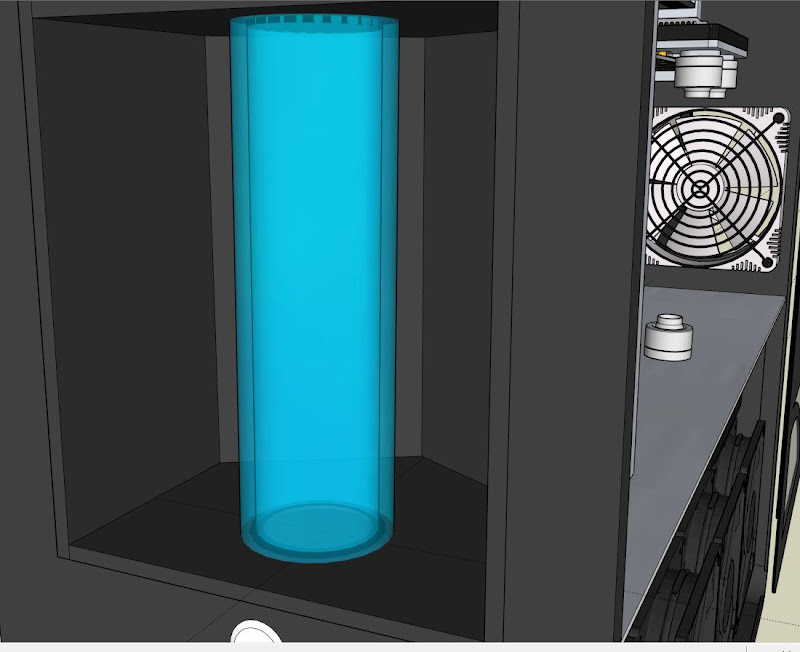
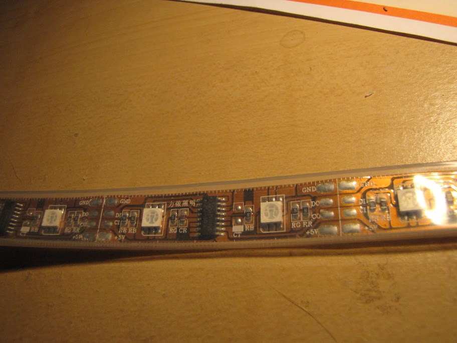
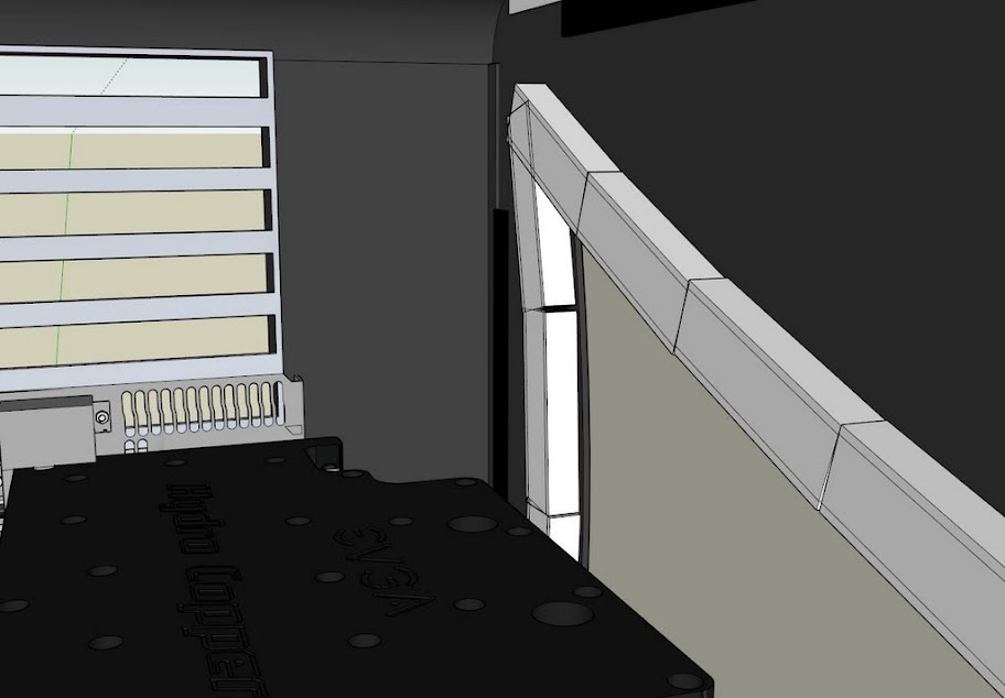
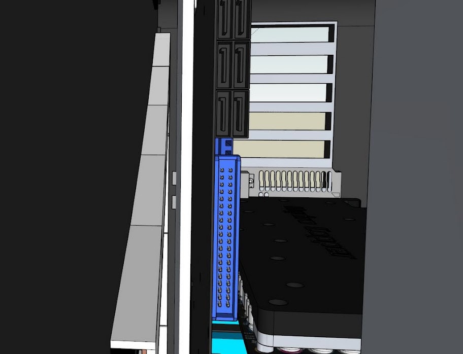
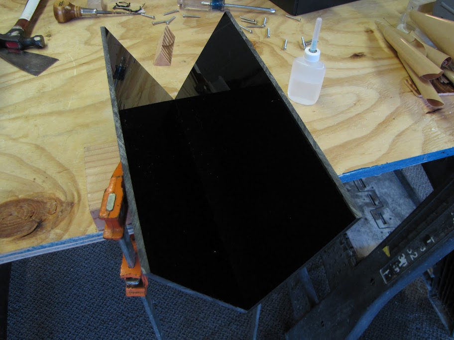
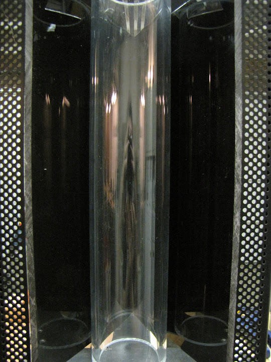
I wanted to find some way to bring my lighting plans into the front of the case elegantly, and I landed upon what will possibly be the most obvious, and yet most creative part of the build yet... I will put an actual prism inside of the reservoir center! Crazy, no? :p I plan on lighting it from the top and bottom using embedded multicolor LEDs so that I can shine light into the prism and hopefully get some interesting color effects. I am also thinking about embedding lights around the rim of the tube part of the reservoir, so I can light that acrylic as well. I needed something in the center of the reservoir anyway to prevent a water vortex and make sure I get a good flow of water throughout the tube, so this should do nicely I think.


    4) I decided to drop the plans for any other case features in the front. I don't want there to be too much going on in the front that would clutter up the design or take away from the central feature. The only thing I might still do is back the front plate area (which is made out of aluminum and perforated with holes for ventilation) with some frosted acrylic that I can light, to give the whole face a feint glow, while blocking the inside of the case from external view and dust/pet hair.

    5) I'll be adding a fill port to the top of the case, and incorporating it into the 'prism' design on the top somehow. Maybe center it on a small clear or frosted acrylic window. This will make it MUCH easier to fill and drain the case, and will bring the front together nicely I think.

    6) I'll be replacing the standard front ports with a new USB 3.0 front, so I will most likely have to fill/sand/re-cut it to the correct shape. Glad I taught myself that technique with the bondo bumper repair... looks like it will come in handy.


    So... I have some clean up on the design to finish up my ideas, and maybe I'll get to cutting the top part of the case tomorrow, since I have the day off! (Yay Labor Day weekend!)

    Just for fun... here's the evolutionary process of my front-reservoir design so far:

    EVGA z77 FTW -- 16GB of Samsung MV-3V4G3D/US -- Intel Core i7-3770k -- EVGA GTX680 -- Corsair AX850 PSU -- Lian-Li PC-v2000b -- 2x XSPC RX480 Rads -- EK-RES-250 -- EK-DDC Dual Top/pumps -- EK-FC680EN Full Cover block -- Swiftech Apogee HD Block

  9. #59
    Registered User
    Join Date
    May 2012
    Location
    California
    Posts
    96
    I was hoping to get some 'manual labor' done this weekend... but instead, I did a bunch of planning. :p I spent an awful lot of time figuring out the whole radiator thing, as well as yet another new feature I am going to try and incorporate into my design. Here's some shots of where I am at.

    First of all, I finished re-designing the top window and finishing it up... so it is ready to print out and cut at this point!


    Now, you may have noticed the discrete little rectangle at the top front of the case...


    What is that, you might ask? It's what took me 8+ hours to figure out, research, design, and sketchup... that's what it is. :p


    Ta-Da!


    Ok... so it's not as impressive as I made it out to be. :p But it took forever to figure out... mostly because of all the hardware/mechanical parts to it. Here's a shot of the inside of the case, where all the 'business' is:


    What you are seeing is the back side of the USB socket, a spring, and a push-push latch. The spring will be pushing against the top of the case, so that when the whole thing becomes unlatched the spring will pop the door open.


    The push-push latch is one of those plastic little snap-lock things... when you push on it once, it locks the little 'strike plate' in place. When you push it again, it pops open and ejects the strike plate. The strike plate will be attached to the top of the case, and the push-push latch will be attached to the USB door. When the door is open all the way by the spring, it will catch on the front of the case by a small 'notch' sticking out of the front where the USB ports are.

    Nifty, no? But that's not the best part....


    The whole business also doubles as an access port for filling the reservoir!

    By pushing lightly against the USB face to bend the 'notch' back far enough, the whole unit can pivot on it's hinges a full 90 degrees, revealing the top of the reservoir below it, which will be sealed by a standard G1/4 cap that is recessed into the top of the reservoir.

    I still have some details to work out on the mechanics (like how the spring will be mounted, and if I need to do some fancy work with the push-push latch to get it to connect with the strike plate right), but I think the design is most of the way there. In the interest of proceeding with the case while I work out the details, I think I might just substitute in a simple window to cap the opening... just so I can keep moving forward.

    As always, totally open to suggestions on how I could accomplish this easier. I'll be the first to say that I am 'mechanically challenged'... and usually cook up crazy ways to accomplish something using custom parts that otherwise already exist. :p I would love to be able to use some kind of 'self opening hinge' in place of the complicated latch and spring stuff... but the only one I could find was for a huge cabinet door...

    Till next time!
    EVGA z77 FTW -- 16GB of Samsung MV-3V4G3D/US -- Intel Core i7-3770k -- EVGA GTX680 -- Corsair AX850 PSU -- Lian-Li PC-v2000b -- 2x XSPC RX480 Rads -- EK-RES-250 -- EK-DDC Dual Top/pumps -- EK-FC680EN Full Cover block -- Swiftech Apogee HD Block

  10. #60
    Registered User
    Join Date
    May 2012
    Location
    California
    Posts
    96
    Finally getting a chance to post this update here... It's from a week or two ago, but every time I checked to try and post, XS was down...

    Anyway, after being stumped by the USB door / access panel stuff for a few days, I decided to set it aside and move forward with other portions of the mod. Hopefully a good idea will come to me through divine intervention.

    I started the weekend off with cutting the last major part of the case... the top! As with the sides, I started by printing out a to-scale version of the design from sketchup:


    Then, after covering the surface in masking tape to help protect it while cutting, I taped the design on top.


    After about an hour of trimming with the jigsaw, the design part was done:


    For the top USB door 'square' I opted to use the dremel... The work was a bit too tight to use the jigsaw, and I wanted to try and preserve the 'scrap' piece to use it for the actual door if possible. Rough cut: done!


    I'm still impressed by how accurate the jigsaw is when working with this thick aluminum... to think that I was concerned it would be jumping all over the place making a massive mess... sure, the dremel could probably do a similar job with about 10 disks and 10x the time/effort. The accuracy shows even in the scraps, which are only 3-4mm thick but fully in-tact:


    After a bit of cleanup with various shapes of metal files, looking pretty good:


    The super confusing reflections from inside the case... it's like a house of mirrors!


    That's all for day 1. Now on to day 2! First, I spent the morning playing with the design for the radiator housing... getting it precise and such so that I had a template to work from:


    The plan is to have the two radiators simply sitting back to back in the housing... maybe with a bit of rubber or neoprene between them to dampen any vibration and give a good seal. The pump will be mounted on the two prongs sticking up from the top:


    I'm also planning on using the gap in the platform to feed the cables from the fans through, to keep everything neat down there. I'll probably drill a small hole for each fan in the bottom/side area, and they will all hook up to some molex splitters down there.


    The fans will be mounted on the outside, of course, and screws will run through their mounting holes, through the acrylic housing, and into the radiator, sandwiching it all together.


    Still haven't totally decided on the color of the acrylic... here's an option with clear / grey acrylic:


    And one in black...


    Hmmm

    Anyway... now that the design was done, I ran down to the local hardware store and picked up some 1/2" MDF. Why MDF, you might ask?


    To make a template, of course! I've decided I will try my hand at using that fancy table router I borrowed a while back... and what better time to try, than when I have to produce (at least) two identical pieces?

    (Jack doubts my process, as is clear by his inquisitive stare... but I'll show him 'I know what I'm doing.' :p)

    So as usual, I printed out a template from Sketchup, and taped it to the MDF:


    Using a technique I discovered while figuring out how best to trace the template onto the subject, I went over every line with a razor knife. This scores the surface with a bit more permanent design, so that I can toss the paper template that tends to curl up and move around while I am working on it.


    Now, off to work with the jigsaw (and a wood cutting bit, of course):


    The MDF and jig were a delight to work with... nice smooth cuts, no jamming or anything. Considering how many awkward angles there were, there were no real mistakes to speak of. I got into the sharp conclave corners by first cutting in from both sides, then cutting a curved line from one end, through the middle, meeting up with the corner of the other end... then just went back over the cut to remove the curved area:


    Inside area: done.


    Pretty sharp angles, for a first pass and free hand!


    Now, to clean up some of the 'wobbles' in the flat lines, I used some sandpaper wrapped around one of my metal files. I neglected to pick up any woodworking files while I was at the store buying wood... But, this ended up working rather well. I did a fair amount of 'how to' research online before going through this process... and the one thing that all guides universally agreed upon, was to spend the extra time getting the template just right. So, elbow grease: liberally applied.


    And now a similar process to cut out the outside area. Template: done!


    After that, a quick trace on the acrylic, so that I can cut it out into a more manageable size... using what else... my jigsaw! :p


    There we go... much more manageable. I used my unibit and drill press to drill a small starter hole for the inside area too, since my router bit doesn't have a 'starter' tip (being that it's a template bit and all.)


    The unibit does a really great job at clean holes... I ran it at about 600 RPM for this hole. Note, all the ragged stuff around the edge is the protective film. I decided to leave it on while machining it, to try and preserve the surface some.


    I also used some double-sided sticky pads I found laying around to adhere the acrylic to my MDF template, that way it wouldn't move around and mess up the cut. I only put one every few inches or so... but I probably should have used more.


    And right when I got to the point where I was ready to route... I got nervous ... :p So, to quell my nervousness (being that this was my 'virgin cut' using a router) I picked up some scrap MDF and acrylic... just to see how it handled.


    Wowee... very clean, no melting... perfect cut.

    Oh... and a total mess. After about 10 seconds.


    Anyway, fear: quelled. Off to the races!


    I had to stop about every 6 inches or so, just to vacuum up the gigantic pile of flakes generated from the router. It gave me a chance to review the progress, though.


    Anyway... lots more of that, and here we are!


    Voila!


    Anyway, that was as far as I got.

    Post analysis:

    1) I still have a little work to do on my template. A few of the lines are still wavy looking (like the bottom right corner area there) and it is super obvious on acrylic. Even the smallest uneven surfaces on the template are greatly exaggerated by the router, so I will need to be SUPER accurate. Fortunately, I can still salvage this piece by sanding down the template a bit more and running this piece through again.

    2) Routers are fun. And they make amazing messes.

    3) I have a feeling I will be using the router a lot more.

    Anyway, that's all for now! I did order (and receive) a bunch of latches for my USB door... so I am rapidly approaching a point where I will have to figure out what I want to do with it. Thanks!
    EVGA z77 FTW -- 16GB of Samsung MV-3V4G3D/US -- Intel Core i7-3770k -- EVGA GTX680 -- Corsair AX850 PSU -- Lian-Li PC-v2000b -- 2x XSPC RX480 Rads -- EK-RES-250 -- EK-DDC Dual Top/pumps -- EK-FC680EN Full Cover block -- Swiftech Apogee HD Block

  11. #61
    Xtreme Guru
    Join Date
    Dec 2009
    Location
    Latvia, Riga
    Posts
    3,972
    Imho it's a bit wrong decision to go for rad sandwich. You may have worsened rad subsystem cooling efficiency at low/silent rpms. Or you'll get almost same cooling from those two as what you'd get from single rad.

  12. #62
    Registered User
    Join Date
    May 2012
    Location
    California
    Posts
    96
    I did actually see that post (via a re-post on Martin's Liquid Lab), and the results were pretty interesting to say the least. To be fair, I didn't actually think to test just a single radiator on my system to see how it stacked up compared to two radiators in the various configurations. Probably should have... if for no reason other than curiosity. Perhaps if I have some time this weekend I will put the mess back together and try it out. Either way, the rad sandwich (FAN > RAD > RAD > FAN) ended up being the most effective configuration out of the various layouts I could accomplish in the bottom of my case... I did some somewhat extensive testing (Empirical, of course, but I'm not claiming my results are good for everyone, just my particular situation) which you may or may not have seen in earlier posts on this build log. I'm using mid-rpm fans (Scythe GT1850's at stock speed) so I have some pretty good air movement and would be surprised if airflow was an issue. His testing was with 800 and 1200, and the 1200 tests had within 1 degree of separation... so I'd wager the 1850 RPM fans will have an even smaller margin... likely within the margin of error.

    Excuses aside... if I had some way to fit the two radiators completely separate in this case, I would do so in a heartbeat. Alas, despite it's size, I simply cannot get two 120x4 radiators in the system. As a result, I took the compromise solution and accepted a possible slight loss in performance (what's a degree or two, anyway?) for a large gain in aesthetics. :P If I were trying to win an extreme cooling award, I might reconsider... but this is a gaming rig and an everyday use computer. I factored in form as well as function during the design.

    Thank you for bringing this up, regardless. If I hadn't seen it already, you might have ruined my afternoon.
    EVGA z77 FTW -- 16GB of Samsung MV-3V4G3D/US -- Intel Core i7-3770k -- EVGA GTX680 -- Corsair AX850 PSU -- Lian-Li PC-v2000b -- 2x XSPC RX480 Rads -- EK-RES-250 -- EK-DDC Dual Top/pumps -- EK-FC680EN Full Cover block -- Swiftech Apogee HD Block

  13. #63
    Xtreme Guru
    Join Date
    Dec 2009
    Location
    Latvia, Riga
    Posts
    3,972
    Oh. I retract suggestion then. If you'll run 1850 GTs at max you'll definitely gain more cooling then from one rad even with sandwiched rads. Of course two separate rads will still win, but sandwiched with powerful fans will not loose that badly.
    (sandwiched rads = behave like more densely finned high FPI rads, worse at slow/silent speeds due increased airflow resistance and cooling 2nd rad with preheated air by 1st, more effective due higher fin heat exchange area when more air pumped through).
    P.S.
    Options to separate rads probably are only by making wider extruded sides, or putting rads at some angle, or mounting one rad externally, or at top of case .. but yeah, all of these options are compromising other areas, like design, dimensions, work required.
    Last edited by Church; 09-21-2012 at 05:44 PM.

  14. #64
    Registered User
    Join Date
    May 2012
    Location
    California
    Posts
    96
    Quote Originally Posted by churchy View Post
    Oh. I retract suggestion then. If you'll run 1850 GTs at max you'll definitely gain more cooling then from one rad even with sandwiched rads. Of course two separate rads will still win, but sandwiched with powerful fans will not loose that badly.
    (sandwiched rads = behave like more densely finned high FPI rads, worse at slow/silent speeds due increased airflow resistance and cooling 2nd rad with preheated air by 1st, more effective due higher fin heat exchange area when more air pumped through).
    P.S.
    Options to separate rads probably are only by making wider extruded sides, or putting rads at some angle, or mounting one rad externally, or at top of case .. but yeah, all of these options are compromising other areas, like design, dimensions, work required.
    Glad you agree on the 1850's making the difference... that's what I was hoping, anyway, and my tests seem to back it up thus far. You're justification about the sandwiched rads behaving simply like a much thicker rad with more FPI is exactly what I had in mind. Unfortunately they don't seem to make 4x120 rads quite as thick as two rads stuck together. :p

    Also... funny you should mention putting the rads at an angle... that was actually a very early beta design I had... putting them in a "V" formation of some sort, kinda like you would see for pistons on a V8 engine. The biggest complication that formation faced was finding some way to mold intake/exhaust shrouds so that I wasn't poisoning my intakes with hot air from the exhausts. I considered the fact that they would be trapped in the same bottom compartment together anyways, so the gain was probably negligible. Extruding the sides would have been a very cool idea, especially paired up with my original "V" formation idea, but yea... lots of work required to get that right... maybe if I am feeling bored down the road, and I want a Prism mk.2

    Thanks for the followup!
    EVGA z77 FTW -- 16GB of Samsung MV-3V4G3D/US -- Intel Core i7-3770k -- EVGA GTX680 -- Corsair AX850 PSU -- Lian-Li PC-v2000b -- 2x XSPC RX480 Rads -- EK-RES-250 -- EK-DDC Dual Top/pumps -- EK-FC680EN Full Cover block -- Swiftech Apogee HD Block

  15. #65
    Xtreme Guru
    Join Date
    Dec 2009
    Location
    Latvia, Riga
    Posts
    3,972
    I was more thinking of not V but L placement (one on side, one on floor, exhaust from both to rad-less side).

  16. #66
    Registered User
    Join Date
    May 2012
    Location
    California
    Posts
    96
    Hello again!

    I've been a little lazy about posting... mostly because I'm spending all my time either playing with my equipment, or playing ON my equipment... (WoW is a big time consumer right now with the recent expansion... )

    Anyway, as was mentioned before, I finally got the spare funds to buy all of my Acrylic needs, so that got ordered and delivered. Here's what I got:

    Boxes!


    First of all... some plastic working tools! Polish, glue, applicators, bits... the works. I've never worked with acrylic before, so I figured I might as well get all the right tools.


    Also, the acrylic itself... it's all cell cast, so it's better for machining. It also has the nice paper masking, as opposed to that annoying plastic film. There's some opaque black 5mm, some opaque white 5mm, clear 5mm, some opaque black 1mm, and a custom cast acrylic tube (whose purpose should be obvious. :p)


    Next, I worked on cleaning up my template from before... now I'm down to laser sharp edges and true corners... it's about as good as it's going to get:


    +

    Once cleaned up, I put the double sided tape on it again, re-attached the clear "demo" that I cut originally, and ran it through the router one more time.


    Once that was done, I moved on to trying to line up the holes that I would need to put in it so that I could put screws through the fans, then acrylic, and into the radiator.


    I kinda eyeballed this time around, threw it into the drill press, and came back with something passable... but not super accurate. I put the housing back on the radiator, then traced around the edges that I would need to expand to get the hole completely centered:


    One more pass through the drill press...


    ... and now all the screws fit. Unfortunately... the screws I have are about 3mm too short to actually catch on the radiator threads with the acrylic and fans in place... so I am going to order some more from MDPC-X that will fit correctly (if I would just wake up in time to catch their hours...) Here's how it will look, anyway:


    Anyway, I went on to repeat the whole process (skipping the photos this time, as I've already been there done that with the demo piece of acrylic... except...


    Whoops. Two lessons learned from this mistake...

    1) Don't get excited and feed the router too quickly. It will catch, and detonate your carefully crafted piece, only inches from being done.

    2) Always cut the most intricate/fragile pieces first, then go back and do the simple large cuts. In this case, I traced around the outside first and then went back and did the inside... that's when the thin little piece broke. The second time through, I did the inside first while there was still plenty of support from the extra material around the edges, then went back and did the outside a little more slowly. Strait passes seem much less likely to catch, so it was a bit cleaner that way, and less likely to explode.

    Anyway, I went on to cut two more (successful) pieces like the one pictured above without any other issues. After that, I went on to try and think of a better way to cut out the screw holes so that I wouldn't be 'eyeballing it' anymore... which wouldn't be possible anyway, considering i'm making the actual housing out of opaque black acrylic.

    I settled on re-printing out the piece from Sketchup and laying it on top of the actual radiator. taping it in place, then punching screws through to make sure the digital representation I made lined up perfectly with the physical one... and it did. After that, it was just a matter of putting the same paper template on top of the acrylic pieces that I needed to cut, and marked through the holes in the paper with a pen. Easy enough...


    Here's how the pieces all come together, before drilling and assembly:


    And here's the channel at the bottom that I was originally planning on making.


    As I looked at it physically and thought about it, I changed my mind on how best to fabricate this... Instead of one 5mm sheet that the radiator sits on, and a second 5mm sheet that the housing bottom rests on the bottom of the case on, I changed it to buying some 1" thick clear acrylic "blocks" that I will set at the front, back, and center or something like that. I'll drill some channels through it so that the wires can pass through as well. This will allow me to accomplish a few things:

    1) I was originally planning on just gluing all this together, but then I thought it might be a bit troublesome if I needed to remove the radiators from the housing for one reason or another. Then, I thought about tapping the acrylic and screwing it together... but it seems to me like the acrylic will eventually crack and the threading will give way. No good, it has to be more durable. So I landed on these little things called "Heatfit machine screw inserts" that you can force into a hole drilled in the acrylic with a soldering iron, then you can use machine screws for that clean "metal on metal" fastening. Putting the thick 1" acrylic blocks down there gives me plenty of room to drill and insert these fittings. Now I can use the blocks on the bottom to hold the two sides together using metal screws, and I can also secure the radiator housing to the bottom of the case, too.

    2) It greatly reduces the complexity of the piece, lessening the chance that something will be crooked or wonky.

    3) It will provide a better base for the whole unit, which is actually pretty heavy. I was a little concerned about the acrylic glue seams giving way down the road... but now it will be a non-issue.

    Anyway, I ordered the 1" thick acrylic, and I am looking for the best place to order the fittings from...

    Moving right along, I went on to drill the holes for the screws in the sides of the radiator housing using my drill press:


    Not bad, actually pretty centered. I originally attempted the cuts with a 1/8" drill bit, which fit the screws perfectly... but I found the fit to be a little too 'snug', and I would have to be inhumanly accurate with the hole placement to get every one just right. With this many holes in a rigid piece of acrylic... yea... not going to happen. I decided to relax the hole size a little and go with a 5/32" bit. The hole will be completely obscured by the head of the screw and the fancy washer around it (love those brainwashers), and it makes screwing the whole thing together so much easier.


    I did have one screw hole that was just a touch off, so I ended up using my trimming bit for my dremel in the drill press to shave a tiny bit away from the edge of the hole... it worked great, whereas the regular bit didn't want to trim away at an existing hole's edge. +1 for these bits when working with acrylic. You can see the difference in the flutes one on the right, how the cutting edge faces outward, as opposed to the strait bit on the left which is for cutting strait down.


    Anyway, that's all for now... I've ordered the additional acrylic I need, and am actively searching for a good place to find the heatfit hardware... hopefully I'll find that tomorrow, with any luck from somewhere local so I can just go pick it up.

    I also plan on working on the reservoir housing tomorrow... that should be fun!
    EVGA z77 FTW -- 16GB of Samsung MV-3V4G3D/US -- Intel Core i7-3770k -- EVGA GTX680 -- Corsair AX850 PSU -- Lian-Li PC-v2000b -- 2x XSPC RX480 Rads -- EK-RES-250 -- EK-DDC Dual Top/pumps -- EK-FC680EN Full Cover block -- Swiftech Apogee HD Block

  17. #67
    Registered User
    Join Date
    Mar 2011
    Location
    The Great White North
    Posts
    1
    Great how-to on the template and using a router. I just got one and I am keen to experiment. I am enjoying the build.

  18. #68
    Registered User
    Join Date
    May 2012
    Location
    California
    Posts
    96
    Quote Originally Posted by WitchDr View Post
    Great how-to on the template and using a router. I just got one and I am keen to experiment. I am enjoying the build.
    Nice, glad I helped someone out! The router is a great tool for this kinda stuff. Definitely use some practice pieces and try your cut once on scrap before you get to using production material, though... there is much to be learned by just 'trying it once' to get a feel for things like feed rate and angle and such. It also gives you a good picture of where the rough spots on your template are, which otherwise may not be very evident just by looking at it.

    Good luck!
    EVGA z77 FTW -- 16GB of Samsung MV-3V4G3D/US -- Intel Core i7-3770k -- EVGA GTX680 -- Corsair AX850 PSU -- Lian-Li PC-v2000b -- 2x XSPC RX480 Rads -- EK-RES-250 -- EK-DDC Dual Top/pumps -- EK-FC680EN Full Cover block -- Swiftech Apogee HD Block

  19. #69
    Registered User
    Join Date
    May 2012
    Location
    California
    Posts
    96
    So, it's time for a big update!

    First of all, I spent a whole $10 and bought myself a cruddy "already broken" tripod for my camera... but better than nothing! Hopefully this will cut down on the blurry-cam photos and make it a bit easier to get those high ISO shots in low light. If it weren't already broken, it would be a pretty nice tripod... folds up to about 1 foot long, but the legs all telescope out to a full 4' length.


    Anyway... I received the thick block of acrylic that I mentioned in another post, and I went down and picked up those 'press fit' screw fittings, so I figured I might as well go ahead and assemble the radiator housing! I started out by putting the radiators together loosely to get some measurements for the thick blocks they will be sitting on.


    I measured the blocks out to be about 22mm thick in my case, so I just ran my block of 1" thick acrylic through the table saw a few times... or at least I tried to... but found my table saw had died on me. To be fair, it was a table from the 1960's and it had served under my grandfather, and then my father (who backed into it with a truck... twice...), and a short while under me... so I do not blame it. Anyway, off to buy a new table saw!


    (Yes, it's already completely covered in acrylic dust. I couldn't wait to try it out, not even for a picture. )

    Here's the result of that 2 hour and $300 trip to the local hardware store:


    Nice and crisp, exactly level. Well worth the investment. Hopefully this one will last as long as the last one. Keeping trucks away from it may help.

    Anyway, I cut the remaining bars. Here's roughly how I plan on laying them out:


    I plan on using the router to cut some notches along the middle of each of the bars, so that I can route cables along the bottom, but that will come later when I have the wiring all figured out. Here's what it will look like on the case, more or less. I have the bottom of the case upside-down laying on top of it... so you are looking at the bottom of the case right now:


    I need to find a good way to fill those holes in, which were the holes for my prior system that had a 3x120 radiator in the bottom pulling air up through the radiator. I'm thinking I'll just need to find a local supplier of aluminum so that I can get a good sheet of similar thickness, then cut out inserts and 'weld' them in place with some of that weld-on metal putty I have... then just sand them down or something... but yea, that's an experiment for another day. :p

    Now that I had the blocks cut out, it was time to drill the holes for the inserts on the ends of the block, so that I could fit these guys in there:


    So very tiny, and yet so great! Here's the finished product:


    And here we are, all put together (with some temporary screws, mind you... still waiting on the MDPC screws...)


    And here it is in the bottom of the case:


    With the pumps in their bracket:


    Back in the case:


    One thing I need to figure out is how to cleanly get the wires from the pumps down to the bottom of the radiator housing, where I will likely have a power distribution mechanism of some kind...


    And finally, here's some shots of the system with the midplate temporarily installed, to make sure it all fits as expected:


    Phew! Just barely. Less than 5mm to spare. Well... that's all for that part for now. Remaining tasks include sanding the edges to get a nice clean shine, and replacing the temporary screws with some nicer looking MDPC versions, then peeling off the protective backing to see what I ended up with.

    That's all for the major stuff... but I'll leave you with a brief teaser for the next piece I am working on...


    Until next time!
    EVGA z77 FTW -- 16GB of Samsung MV-3V4G3D/US -- Intel Core i7-3770k -- EVGA GTX680 -- Corsair AX850 PSU -- Lian-Li PC-v2000b -- 2x XSPC RX480 Rads -- EK-RES-250 -- EK-DDC Dual Top/pumps -- EK-FC680EN Full Cover block -- Swiftech Apogee HD Block

  20. #70
    Registered User
    Join Date
    May 2012
    Location
    California
    Posts
    96
    Hello again!

    I've been working on little bits and pieces over the past few days, but haven't found a good block of time to make some serious progress. Regardless, here's what I've been working on:

    First of all, I started with cleaning up the edges of my radiator housing. Fresh out of the router, the edges are fairly smooth, but they still have ridges on them... which you can see here:


    Maybe not that big of a deal... but if I'm going all the way on this, I might as well clean that up and make it perfect. I started out with some 400 grit sandpaper to take out the major imperfections and ridges. I wrapped a small piece around a small spare block of acrylic I had from the housing to make an improvised sanding block for small surfaces:


    Worked well enough:


    And here it is cleaned up with some water. Nice smooth surface, but not shiny and clean like the remainder of the housing:


    Next, I broke out the Novus polish kit:


    Starting with a liberal application of #3 and working my way down to #1, I ended up with this:


    MUCH better. You're seeing the sky reflected in the edge, in case you couldn't tell.

    Now that all that was done and I had the edges looking polished, time to put it all together!


    I love the look of the MDPC screws and brainwashers. Just perfect and clean!


    There's one half done. Now, to put the two pieces together I needed some unusual screw lengths... around 8MM long (enough to go through a piece of 5mm acrylic and into the supporting blocks) which I could find in your everyday regular screw, but I wanted to be consistent in my use of MDPC's screws... time for a custom screw length! I started with a longer 20mm screw and inserted it to figure out the exact length needed:


    Ever wonder what those numbers on some of the higher end pliers and wire crimpers are?


    They're for breaking screws at precise lengths without damaging threads. So handy! Just screw the bolt in to the proper length, then squeeze the pliers, and bam:


    ... custom length MDPC screws. :p

    Much better:


    That's that! Radiator housing is done for now. The next small piece will be drilling small holes in the bottom area for routing all the fan cables... but I need a little more time to plan that out. The next task I moved on to was repairing some of the mods I made in my previous watercooling setup on this case:


    I had cut three fan holes in the bottom for the radiator that was facing down at the time, and now I will no longer be using those holes. They were ugly cuts anyway, and I wanted to seal up the surrounding perforations in the case as well to get a good seal in the bottom area. I looked for some similar metal online and in neighboring areas to try and fix the holes, but didn't have much luck. Fortunately, I am thrifty... and I ended up saving all my scraps from the windows I cut earlier in the project. I bet you can see where this is going.


    I arranged the scraps like puzzle pieces and drew out some lines for the shapes I would need to cut in order to fill the holes. Unfortunately, I didn't have enough scrap pieces for all three solid plates, so I had to improvise on two of them:


    A little bit of jigsaw work, and we have our plates:


    A little bit of filing, and they fit like a charm:


    Next step... adventures with bondo! I'll finally be putting my bondo practice to work. Next time!
    EVGA z77 FTW -- 16GB of Samsung MV-3V4G3D/US -- Intel Core i7-3770k -- EVGA GTX680 -- Corsair AX850 PSU -- Lian-Li PC-v2000b -- 2x XSPC RX480 Rads -- EK-RES-250 -- EK-DDC Dual Top/pumps -- EK-FC680EN Full Cover block -- Swiftech Apogee HD Block

  21. #71
    Registered User
    Join Date
    May 2012
    Location
    California
    Posts
    96
    Back from my family vacation finally! Time to make some progress!

    First off, I wanted to post a final pic of the rad mount with my last post... but I realized as I was assembling it that the Dual pump top used 8-32 screws instead of the lovely 6-32 MDPC screws... (grumble grumble)... so I had to find some alternate screws. I couldn't find any nice black ones like MDPC offered... so I have an alternative that I am going to try tonight... hopefully it works out!

    Next, I have started playing with repairing the bottom of the case. I was going to use the bumper repair stuff, but I stumbled upon some metal repair product called 'Steelstik' that looked interesting, so I am going to give that a try and see how it works. Looks like a polymer filler, but you can mix it with your hands like play doh, and form it into gaps and what not. Seems perfect for fixing the holes in the bottom of the case... we'll see how it works.

    I'll be making some progress this afternoon, so hopefully an update on how it goes tonight! =)
    EVGA z77 FTW -- 16GB of Samsung MV-3V4G3D/US -- Intel Core i7-3770k -- EVGA GTX680 -- Corsair AX850 PSU -- Lian-Li PC-v2000b -- 2x XSPC RX480 Rads -- EK-RES-250 -- EK-DDC Dual Top/pumps -- EK-FC680EN Full Cover block -- Swiftech Apogee HD Block

  22. #72
    Registered User
    Join Date
    May 2012
    Location
    California
    Posts
    96
    Well, I made a little progress on the Steelstik stuff and refined my process a bit. The stuff works incredibly well so far... albeit a little messy and smelly. I did take a few pictures, but I don't think I have enough yet to warrant a big post, so I'll save them up when the process is completed and the bottom of the case is completely repaired.

    Also, more delays on the final radiator housing pics... the screws that I thought were 8-32 were actually M4... So i've ordered some new ones online and I should hopefully get them today or tomorrow. Final pics then!
    EVGA z77 FTW -- 16GB of Samsung MV-3V4G3D/US -- Intel Core i7-3770k -- EVGA GTX680 -- Corsair AX850 PSU -- Lian-Li PC-v2000b -- 2x XSPC RX480 Rads -- EK-RES-250 -- EK-DDC Dual Top/pumps -- EK-FC680EN Full Cover block -- Swiftech Apogee HD Block

  23. #73
    Registered User
    Join Date
    May 2012
    Location
    California
    Posts
    96
    Finally, an update!

    I'll start with a continuation of the efforts to repair the bottom of the case. This Steelstik stuff is neat... but I don't think I'll use it anymore. It ended up being a gigantic pain to 'clean up', and I am not certain it's any better than the bondo I was using before. So... lesson learned!

    It comes in a play-doh like bar, and you pinch off pieces of it, then mix it together to form a hard-setting polymer in a few minutes.


    My process was to take a piece that I pinched off and roll it between my hands so I ended up with a long 'snake' of putty, then lay that along the seam I wanted to seal and press it in with my thumbs. I learned quickly that I needed to keep my hands wet at all times, or it seemed to have a preference to bond to my hands rather than the aluminum surface. I did my best to press the stuff flat, so that I would have less cleanup work after it dried:


    I let that dry for 24 hours just to make sure it was completely set, then went at it with an old fashioned sanding block and some 100 grit sandpaper. After 15 minutes of desperately sanding it, I realized I wasn't getting anywhere and opted for something with a little more power... my dremel and a sanding flap wheel that came with it. That worked a little better, but it still took me about two hours to get it to this point:


    ... and it still has some distance to go before its ready. I'm planning on filling the remaining holes on the bottom so that I end up with a smooth surface, and I'll most likely go back to bondo for that. Much easier to work with, same result. :nod:

    Anyway, on to something more 'pretty'... I put the final touches on my radiator housing! First, I found some black screws that actually fit the M4 holes pre-tapped into the pump top. The screws were not quite up to par with the MDPC screws I had been using thus far, though... so I went looking for a solution, and found these little numbers:


    They're sort of like the MDPC brainwashers, but they also sport a cap, for a completely enclosed look. Found 'em at my local hardware store, of all places! Nifty!

    Here's the framework for the housing with the pump installed now (don't mind the mess in the background, the wife had me pulling down christmas ornaments... :p):


    And for the final piece... when I was planning and fabricating the radiator housing, I intentionally left a small 2mm gap between the radiators. I did this because I quickly realized while working with them that they weren't "perfectly true"... each had a slight lean like they were twisted or something, and it made it so the bottom of the radiators met when they were next to eachother, but the top corners did not. They're skewed by about 1mm, maybe less. Normally you'd never notice, but normally you aren't sitting these guys back to back... so yea.

    To fix the gap, I searched around and eventually found some stock neoprene rubber. I went to work tracing it over the radiators and cut it out to get this:


    And applied to the inside of the radiators:


    Voila!


    Now there's a nice air-tight anti-vibration seal between the two radiators. Couldn't have worked out better! Glad the radiators had that distortion... if they didn't I probably would have just put them directly against each other, then thought of this down the road and wished I had done it.

    And at last... here are some pictures of the radiator housing completely assembled!


    Phew! Finally a large portion of this mod is done, and arguably the most complicated piece. The completed radiator housing, along with the completed case wall and top designs, puts me at probably 25% done with this mod. Finally getting somewhere!

    Next up, continuing to fix up the case... then maybe the reservoir!

    Thanks for following!
    EVGA z77 FTW -- 16GB of Samsung MV-3V4G3D/US -- Intel Core i7-3770k -- EVGA GTX680 -- Corsair AX850 PSU -- Lian-Li PC-v2000b -- 2x XSPC RX480 Rads -- EK-RES-250 -- EK-DDC Dual Top/pumps -- EK-FC680EN Full Cover block -- Swiftech Apogee HD Block

  24. #74
    Registered User
    Join Date
    May 2012
    Location
    California
    Posts
    96
    Guess what showed up?


    Well, if the big logo on the box wasn't enough of a clue...


    Hooray, a pile of fittings! Bitspower was generous enough to sponsor me with all these nice fittings, completing all of my plumbing work... Which means...


    Finally, all assembled! What a load off that it all actually fit together like I planned.

    What you are looking at is the link between the two radiators, along with a thermal sensor (the plug on the top right) and at the bottom a D-Plug type quick disconnect leading down through the bottom of the case. For now, I stuck a piece of acrylic down there to simulate the bottom of the case.

    Here's the whole kit, slotted in the bottom of the case approximately where it will go in the final setup:


    Now, for the part I am most concerned about... the drain meets the case right where there is a seam/flap to hold it together:


    I'm thinking I can just cut a circular section out of the tab and underlying slot that the tab comes through so that the area is flat. If that doesn't work out, I can always just remove the tab and fill the slot, sealing the seam permanently together. I'm not exactly sure why the seam is there anyway... probably just made manufacturing easier or something.

    See you next time!
    EVGA z77 FTW -- 16GB of Samsung MV-3V4G3D/US -- Intel Core i7-3770k -- EVGA GTX680 -- Corsair AX850 PSU -- Lian-Li PC-v2000b -- 2x XSPC RX480 Rads -- EK-RES-250 -- EK-DDC Dual Top/pumps -- EK-FC680EN Full Cover block -- Swiftech Apogee HD Block

  25. #75
    Xtreme Addict
    Join Date
    Apr 2011
    Location
    North Queensland Australia
    Posts
    1,445
    Quote Originally Posted by Noblesoft View Post
    Pure. Sex.

    That's the money shot right there.

    So freaking awesome.

    -PB
    -Project Sakura-
    Intel i7 860 @ 4.0Ghz, Asus Maximus III Formula, 8GB G-Skill Ripjaws X F3 (@ 1600Mhz), 2x GTX 295 Quad SLI
    2x 120GB OCZ Vertex 2 RAID 0, OCZ ZX 1000W, NZXT Phantom (Pink), Dell SX2210T Touch Screen, Windows 8.1 Pro

    Koolance RP-401X2 1.1 (w/ Swiftech MCP35X), XSPC EX420, XSPC X-Flow 240, DT Sniper, EK-FC 295s (w/ RAM Blocks), Enzotech M3F Mosfet+NB/SB

Page 3 of 6 FirstFirst 123456 LastLast

Tags for this Thread

Bookmarks

Bookmarks

Posting Permissions

  • You may not post new threads
  • You may not post replies
  • You may not post attachments
  • You may not edit your posts
  •