


Hi,
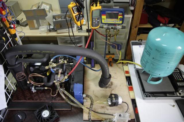
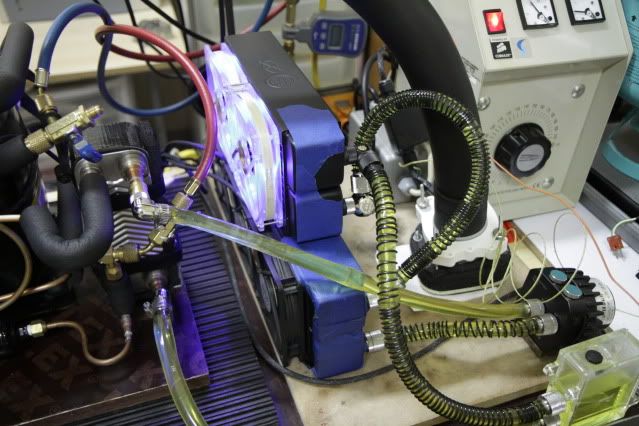
Compressor: Danfoss SC21CL
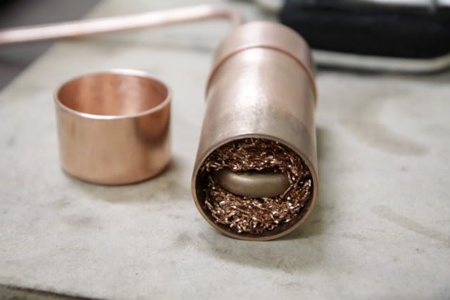
Captube : 0.036, 245cm
Condensor: plate HX 20 plates
At first I only used the R507, but the cooling performance was not as good!
I then used a mixture R507+Propane The result was as follows ..
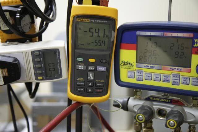
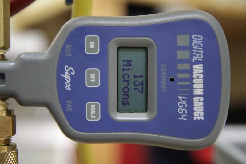
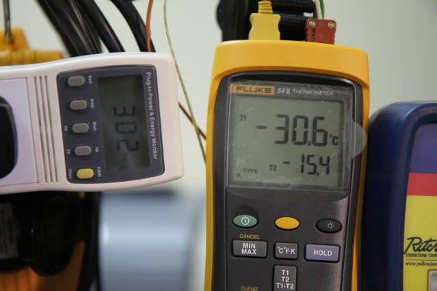
UNLOADED
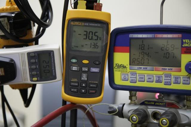
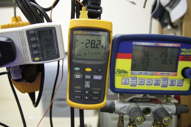
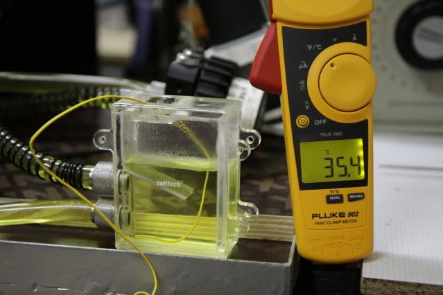
LOADED 250watt,
I could not make the cold stable for more than that!, Because I want 280 watts or more..
What do you advise me? And what do you think is the maximum load can I do with this unit?
Thanks,


 Reply With Quote


 3DMark2001SE -> Favourite Game!


 I forgot "you must"


Bookmarks