

please refer to #90...Originally Posted by colex


please refer to #90...
Thanks for reply.
I think it's best don't make mod for the owners of this pump revision!
PC: Liquid Cooling | i7 920@3.36 V1,05 | Asus P6T deluxe | Corsair 12GB | Corsair SSD F120 | ATI HD5750 | Plextor PX880SA | Corsair HX520W | NETGEAR DG834N | Notebook: Vaio FE21M | T7200 | 2GB | Hitachi 7K500 500GB | wi-fi 5300N | LCD: Samsung LE26R86 | Dell S2409W | Apple: iPhone 8GB V.3.1.3 | IEM: Westone UM-2 | DSLR: NIKON D7000 | 50 f1.4G | 16-85VR | 70-300VRII
I have mine on order, but I don't know how long it takes to get to California. I'm going to install it into a DDC 3.25 pump with aftermarket XSPC top.
I took a look at the datasheets and wanted to figure out the power dissipation. Plugging in the typical for Im, Ron(H), and Ron(L) with 12v and 2.35A I get 3.3675W. According to the spec sheet a value of 39C/W is given for a 140mm x 70mm x 1.6mm 50% CU board. Since swiftech's pumps are only 60mm x 60mm and the board has a big hole in the middle, I'm just going to assume the second rating given which is 65C/W. So P = ~219C. I think I read somewhere that the base gets to about 50C and that is on the plastic. So Tj = 3.3675W x 65C/W + 50C = ~269C. Of course I'm not factoring in the heat removal by the water.
Maybe I messed up somewhere, but it doesn't look like this would work or for very long in a 3.25 since the thermal shutdown is 165C-180C. Datasheet also says to keep under 150C Tj. Didn't really think of this before ordering, though I wish the IC was mounted to the other side of the PCB. Then at least I could put a heatsink with direct contact onto the IC.
Yeah, I don't think I would consider using this board on a blue impeller motor. If you want to try it out, it should work well on bmaverick's DDC-1 pumps though. They are the original black impeller DDC-1 and DDC-1T motors.
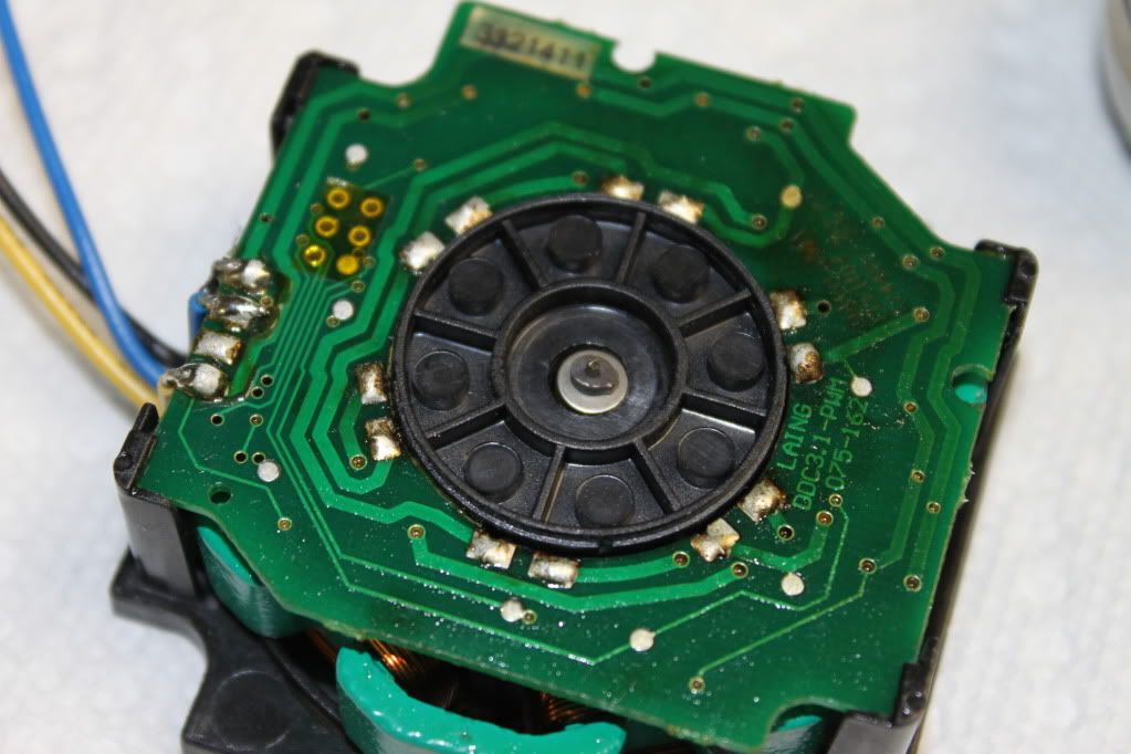
Will it work on these PCBs? I ordered two of the ebay DDCs that use the expansion compensators but they don't seem to work. I was hoping just to through the new PCB on them.

That looks like a DDC3 series PCB. Does it have a blue impeller?
DDC-1 series look like this and have a black impeller:


Yeap
SourceThis is the rare special edition Laing DDC-3.2VC with built in liquid volume compensator. It is the much more reliable and newer BLUE rotor 18W version with the original LAING 3.3 PCB.
An unfortunate person is one tries to fart but sh1ts instead...
My Water Cooling Case Build (closed)
Yes they are blue. I think I may still try to mod them though. I'd rather not just have these two dead DDCs laying around.
Shame I haven't taken any electronics after high school as this just went WAY over my head.
I tried to read over the spec sheet but it just looks like a bunch of gobbledygook to me.
How would I find out what size resistor is going to be needed between VSP and Vref in order to keep the amperage at safe levels?
Ya those are the ones I have and they don't work.
lowfat
So basically you have bought the item that don't work? care to get your money back? oh BTW, what that fourth cable is for (the red one)?
I would suggest to use a potentiometer, connect it to those pins and turn it off, then try to start the pump and increase the resistance step-by-step.How would I find out what size resistor is going to be needed between VSP and Vref in order to keep the amperage at safe levels?
Though even 2.35A is safe for this chip, according to this
An unfortunate person is one tries to fart but sh1ts instead...
My Water Cooling Case Build (closed)
Like SpuTnicK said you'll probably have to just connect a pot and guess. I finally received my kit and it looks like VSP is being fed from Vref to set VSP to 5v.
Vad(H)<VSP<=Vref = 100% speed
Vad(L) is 1.2v and Vad(H) is 4.1v
I'm not sure what current is flowing through it, but it looks like either 1mA or lower. We want to drop the 5v down to at least 4v. So using Vdrop / I = R
1 / .001 = 1000 ohms.
2 / .001 = 2000 ohms.
etc...
If the current was lower then it'd be a greater resistance. So make sure to start out high then reduce resistance. I'm still debating whether I want to install it on my pump or not. I was thinking you could use the motherboard to control it, but VSP requires an analog signal, so no pwm
There was never any mention of warranty on the eBay page and they did work for a while before dying out. The red wire is for 5V, which I am not sure why it is there but the pumps wouldn't work without it.
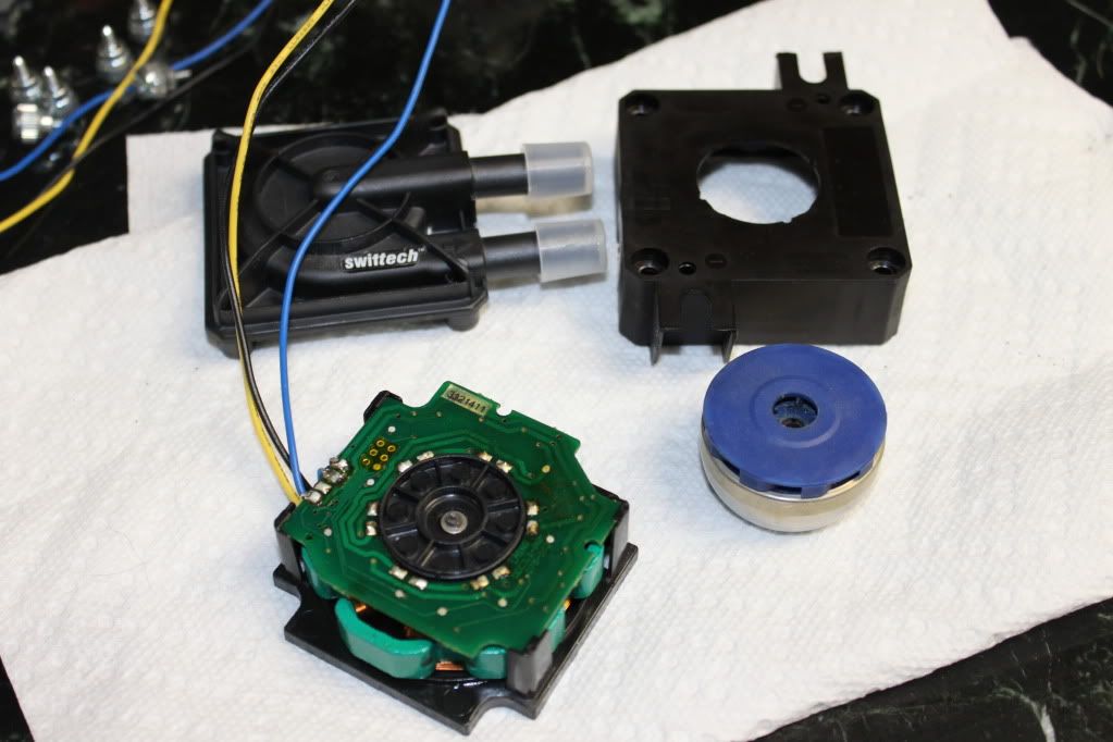
EDIT: I finally got my pre soldered DIYINHK PCB. I can see the problems w/ installing it on a DDC 3.2 already. Since all the coils are soldered to the inside of the PCB instead of the outside it is a tad on the difficult side of things to remove them. Plus the coil wires are too short to reach where the need to be on the new PCB.
Last edited by lowfat; 03-24-2011 at 10:11 AM.

The 5V is probably to feed the logic of the control chip.
The Cardboard Master Crunch with us, the XS WCG team
Intel Core i7 2600k @ 4.5GHz, 16GB DDR3-1600, Radeon 7950 @ 1000/1250, Win 10 Pro x64
I got the old PCB's off my DDC3.2s. There are 6 coils w/ two wires a piece. However on the new PCB there are only 10 holes for wires to pass through AFAIK. There are two more places where I think the wires should go but no holes to push them through.

Last edited by lowfat; 03-24-2011 at 11:28 PM.
The holes are in places where electric contact from one side of PCB should pass to the other side. So, i guess you should not worry about that, as it is more of PCB developer's duty. Just solder all 12 wires to those contacts and the board should work as planned.
An unfortunate person is one tries to fart but sh1ts instead...
My Water Cooling Case Build (closed)
connect like this, and be care the two ending of each coil cannot be reverse connected.

Last edited by wizard1238; 03-25-2011 at 03:24 AM.
This is Certainly off topic.
but, Lowfat nice picture of that pcb.. it's so photogenic.
and I love John Criton and Mal.
that is all.
If your annoyed by sigs telling you to put things in your sig, then put this in your sigyou know you're addicted to watercooling when:
Getting close. I just hope it works afterwards.


Looks good.Keep us posted. I'm actually waiting about 3 weeks for my circuit boards... And of course good luck!!
Last edited by mochti01; 03-25-2011 at 12:50 PM.
double check the copper wire is not touching/short circuit the PCB before connect the power. it should work immidiately
The PCB can also be place outside the pump housing, you have very long copper wire extended. The heat from the controller will never go into the water loop in this arrangement.
Last edited by wizard1238; 03-25-2011 at 02:06 PM.
Cool!...
I'm really confused after looking through all of the posts... which PCB will work for the blue impeller ddc 3.1?
Intel Core 2 Quad Q9450 Yorkfield @ 3.2GHz | Asus P5Q Deluxe mobo | 2x OCZ Reaper HPC 4GB (2 x 2GB) DDR2 1066 (PC2 8500) | Sapphire 4870x2 | Western Digital VelociRaptor 300GB 10k RPM | Intel 120GB SSD | Western Digital Caviar SE16 640GB 7200 RPM | Hitachi 2TB 7200 RPM | PCP&C 750W Power Supply |Cooler Master HAF932 | Windows 7 64-bit | Dell ULTRASHARP 2408WFP 24-inch Widescreen Flat Panel Monitor
Join Us in the XS World Community Grid Forum & Help Fight Cancer and Other Diseases
Well I got it completed but it isn't working properly. It is trying to pump but it just spurts on and off about 2 times a second. Moving almost next to no water though.
Been a while since I posted here...
Anyways, does anyone know if this would work on the original DDC-2 with ORANGE (gasp I know right) impeller from 2007? I'm thinking about selling mine soon and given it's poor reliability track record, this mod being available might bring peace of mind to whoever may be interested in buying it. Certainly doesn't look too hard to solder the few wires on.
Lenovo Thinkpad X220 - Core i5 2410m, 4gb
waiting on 28nm video cards...
Thanks for trying and sharing, sounds like it's a DDC-1 only mod..
Wait so just making sure, by DDC-1 you mean the old 10W one before they switched to 3.1 and 3.2 right? I thought the PCB for the DDC-1 (black) and DDC-2 (orange) were supposed to be very similar, so could it work on an orange impellered pump?
Lenovo Thinkpad X220 - Core i5 2410m, 4gb
waiting on 28nm video cards...
 Posting Permissions


 Reply With Quote
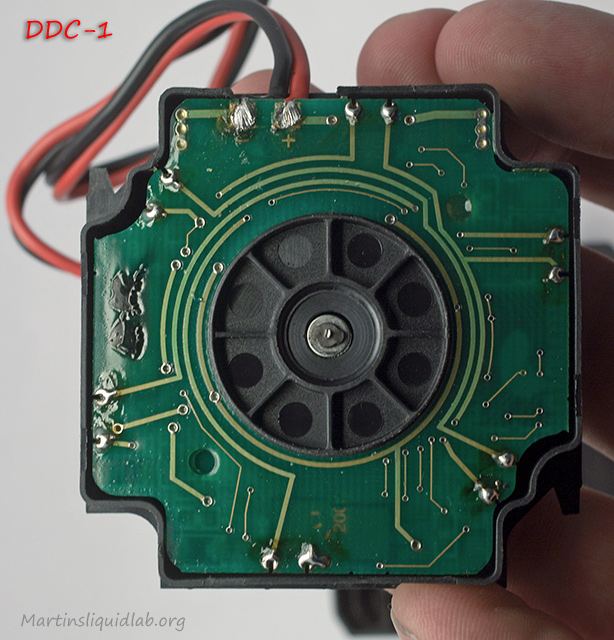
 The extended wire may have chance to short circuit the board, it should be very careful. When using with blue rotor DDC3.x and stock top at full speed, the current is about 2.1A, it's still within the safety limit of this chip(1.5A typ. 2.5A max) Use with aftermarket top is 2.35A, I would recommend connect a resistor between VSP and Vref to reduce the current.
 it cannot read the feedback signal from the coil. it's very common.


Bookmarks