


Hello all. I've been a long-term occasional lurker here, but never got round to posting. Could mods please leave this in the water-cooling section as it's more a home-built passive radiator than a case project, and input and suggestions from the watercooling section would be useful.
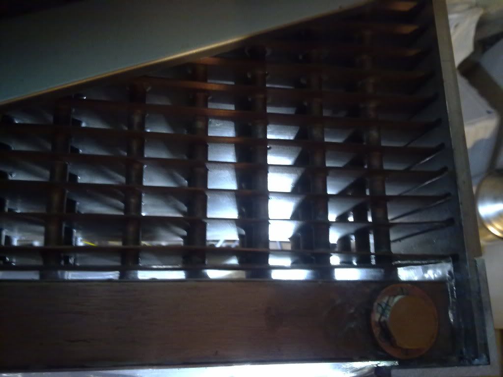
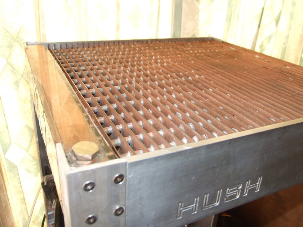
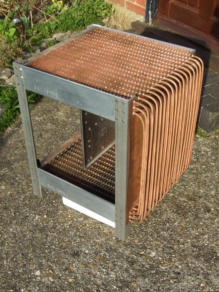
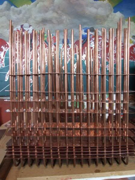
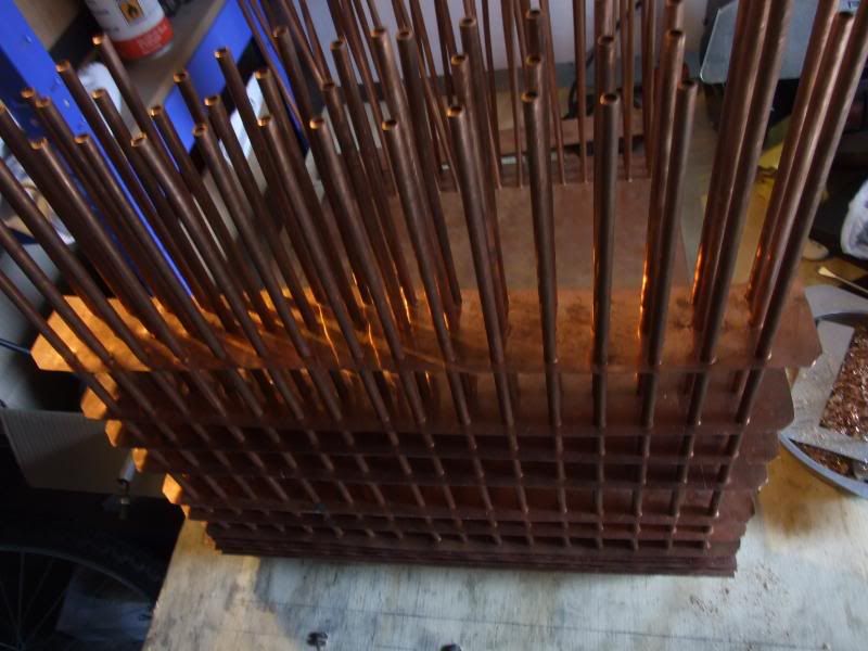
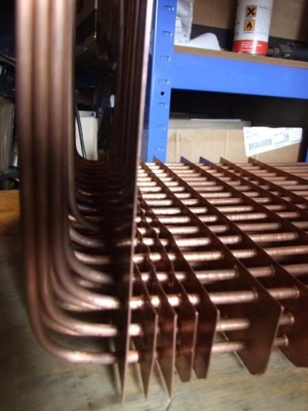
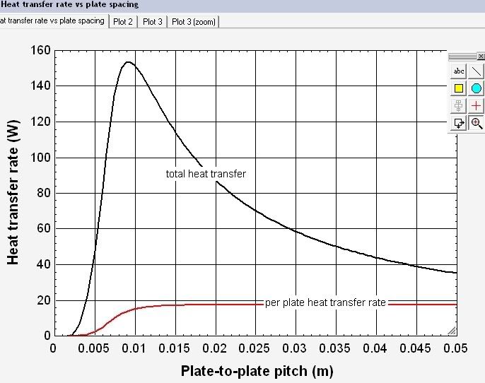
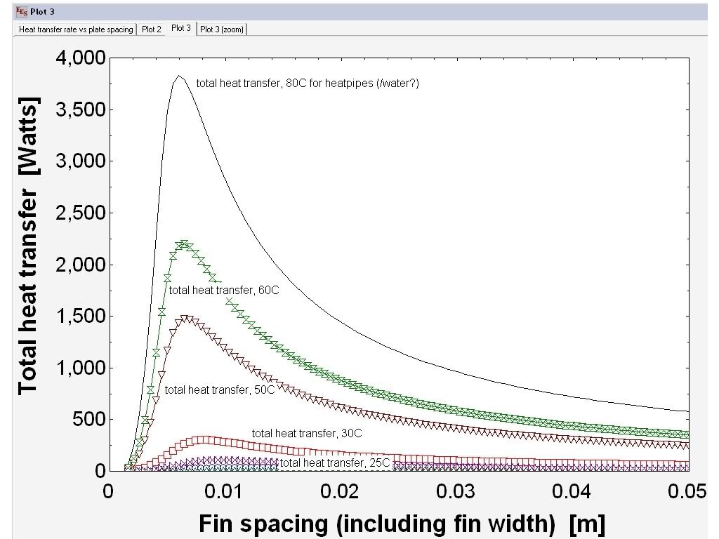
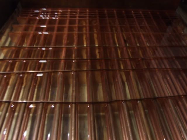
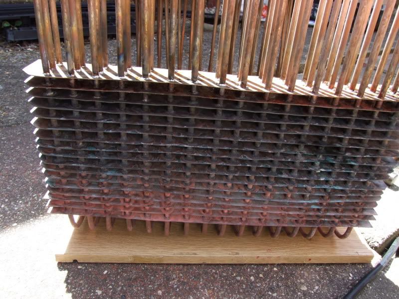
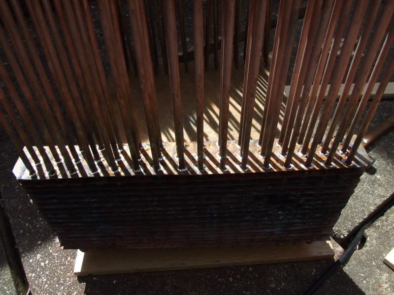
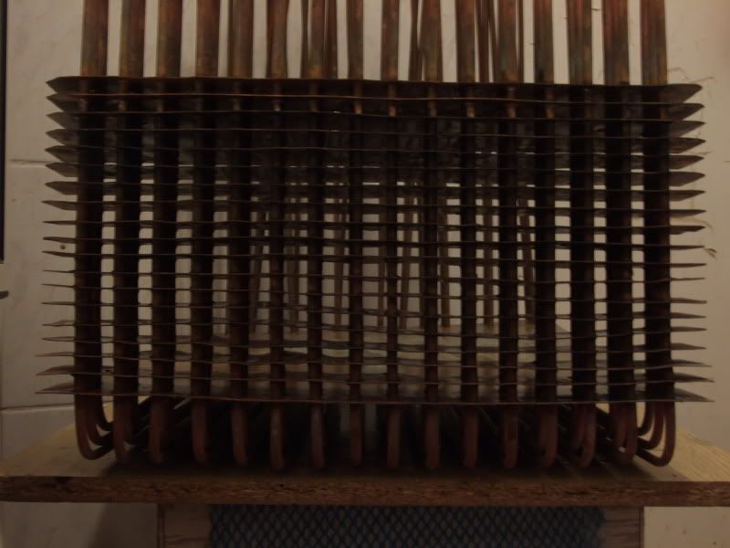
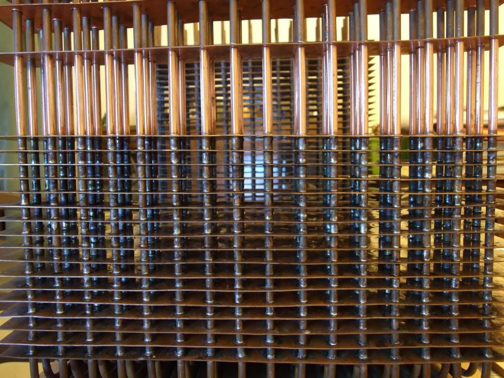
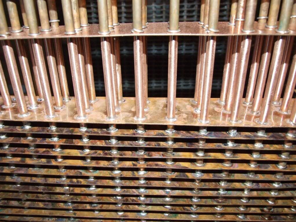
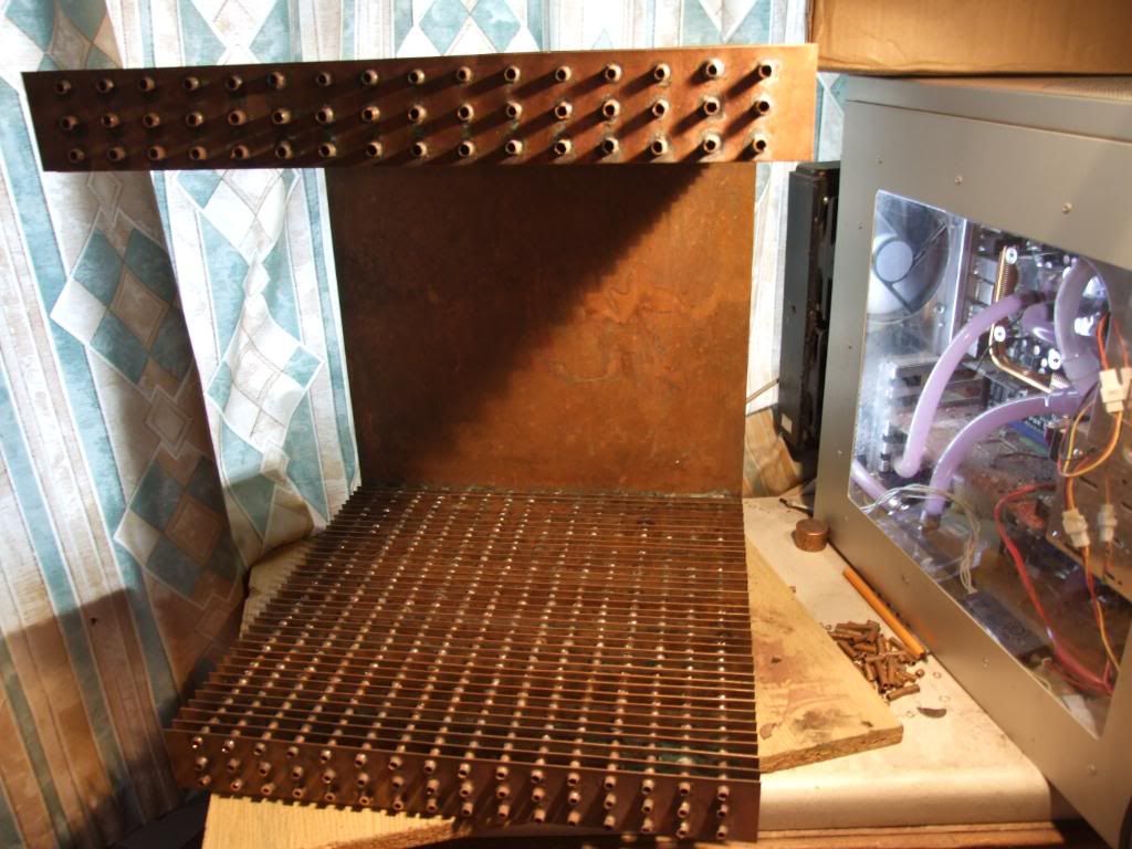
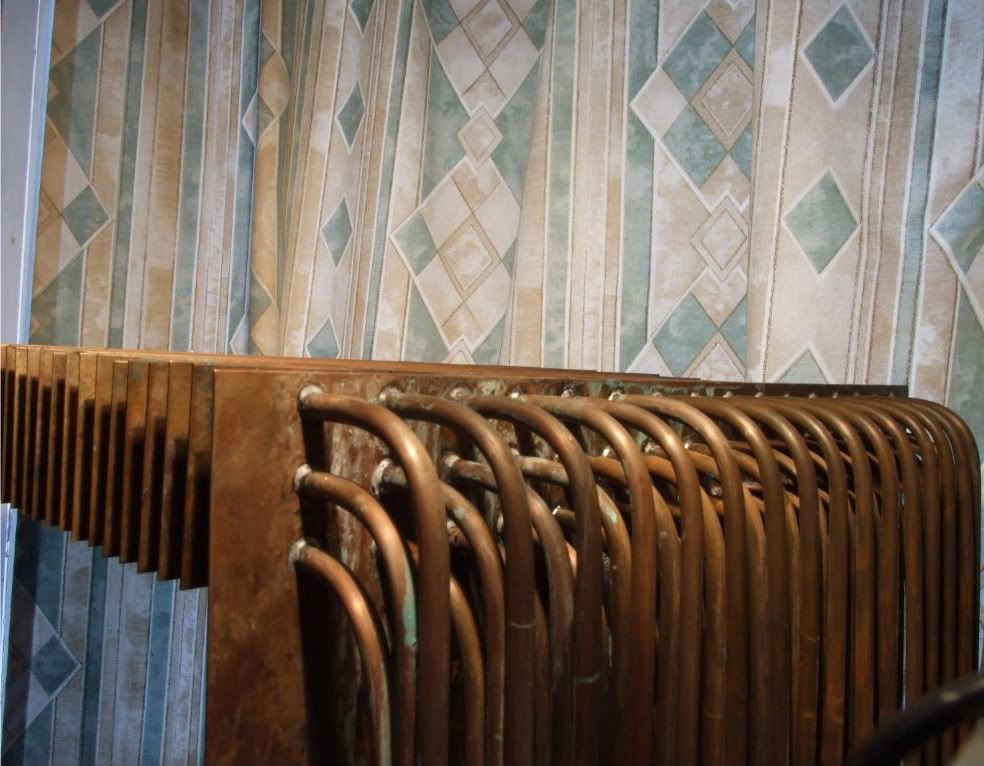
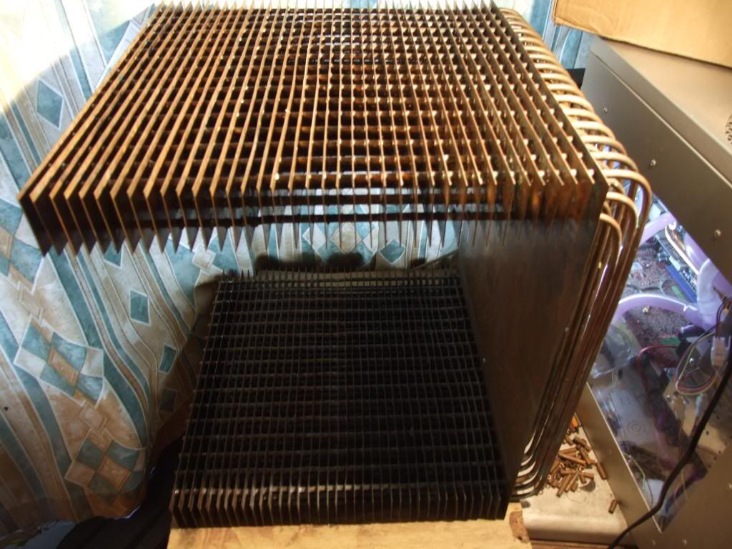
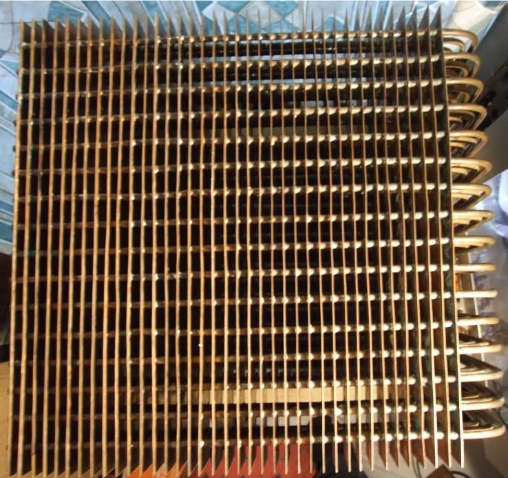
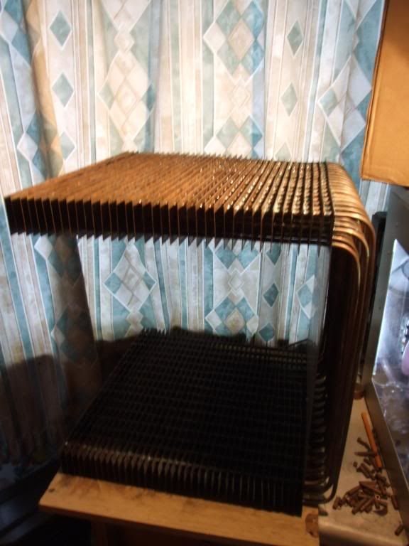
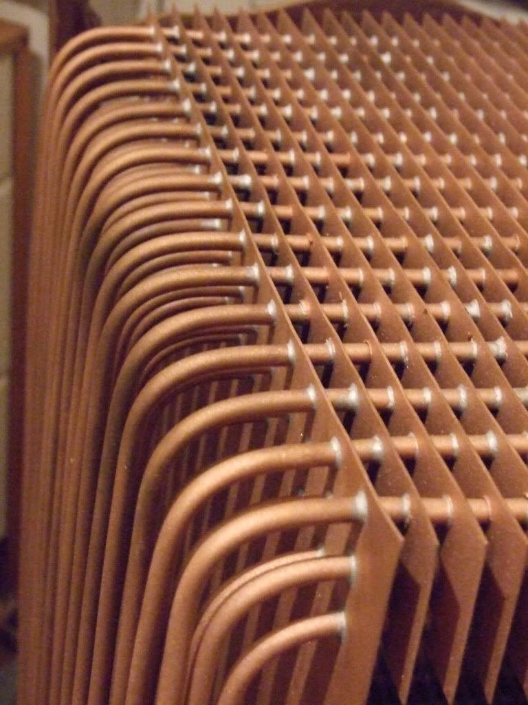
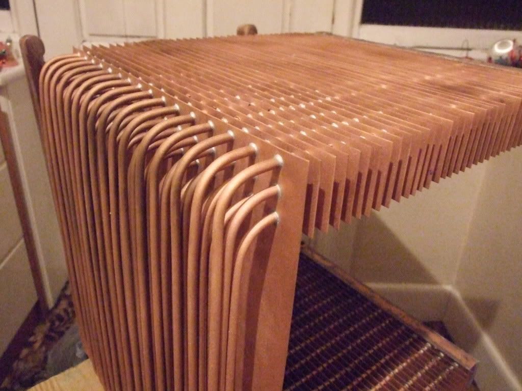
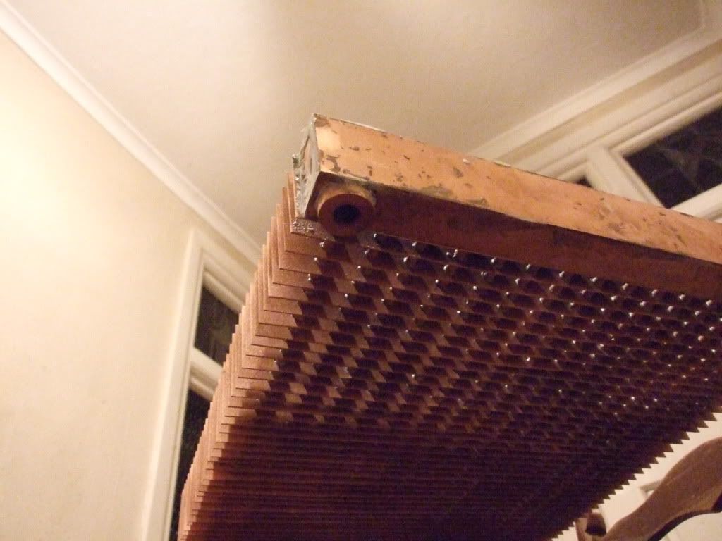
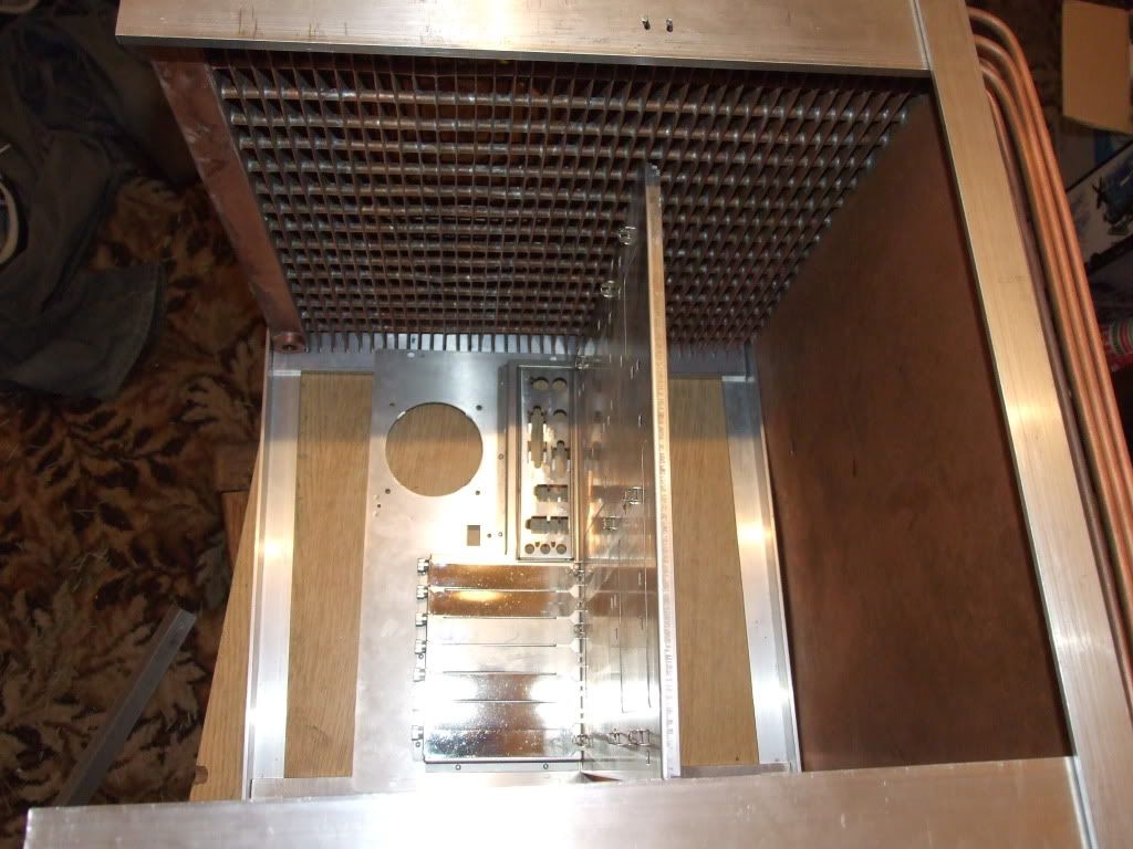
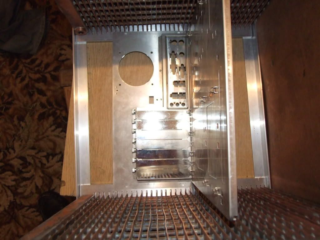
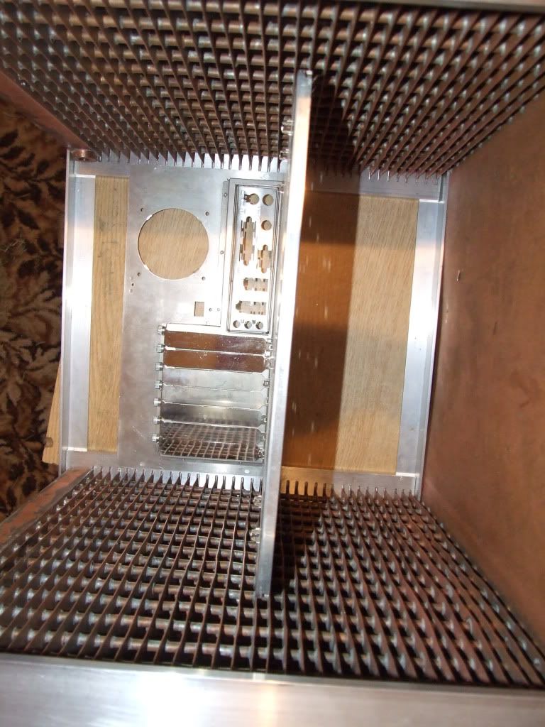
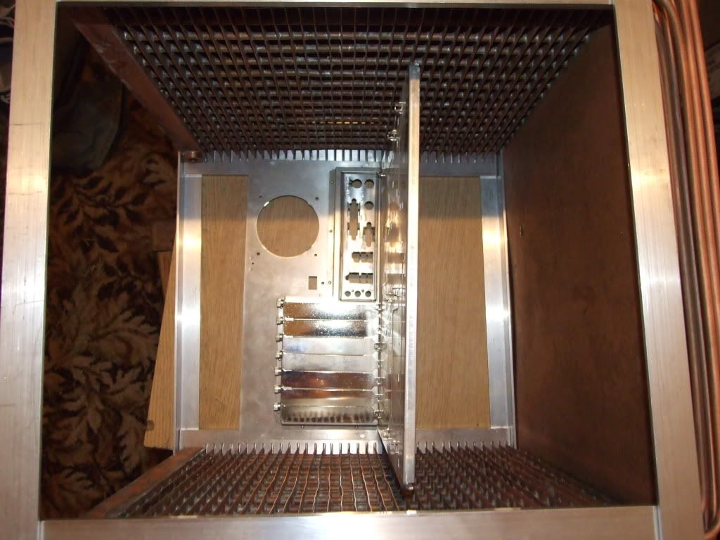
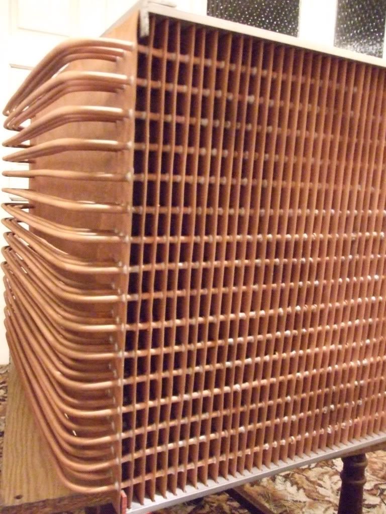
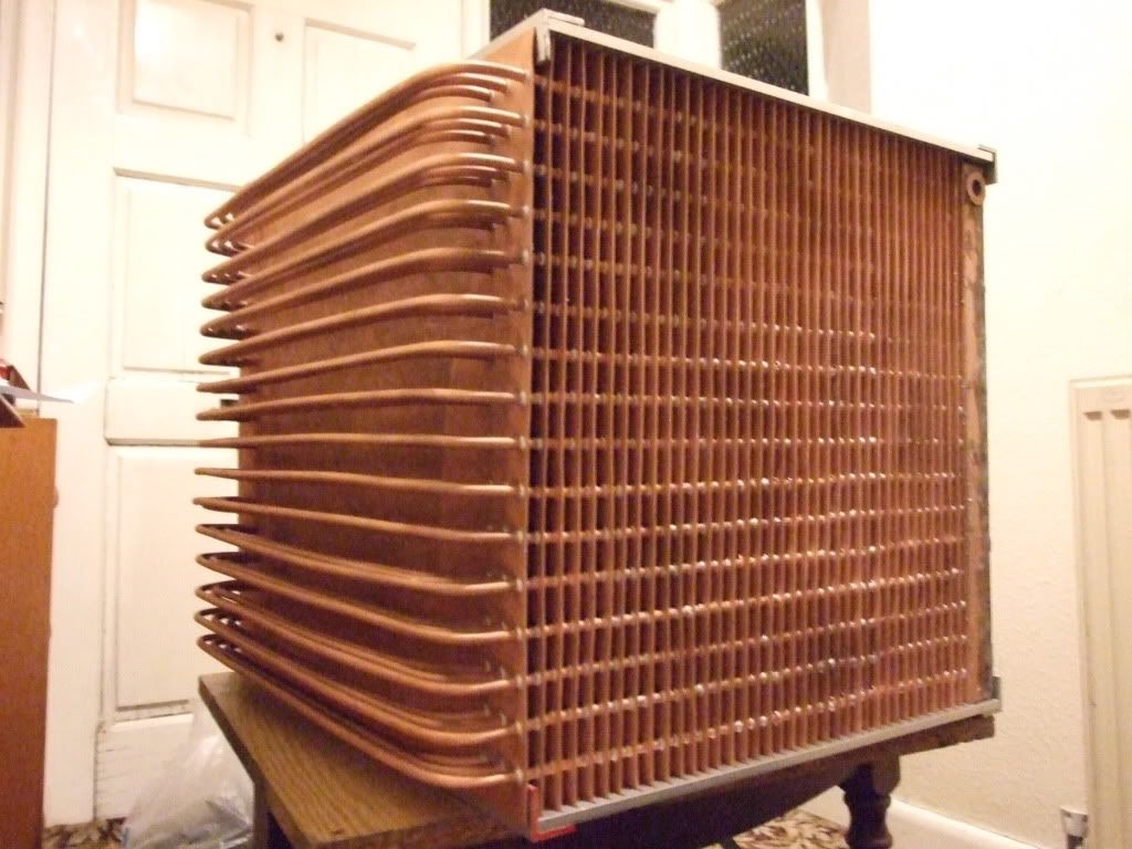
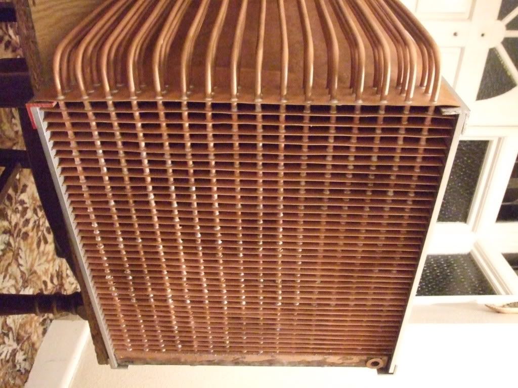
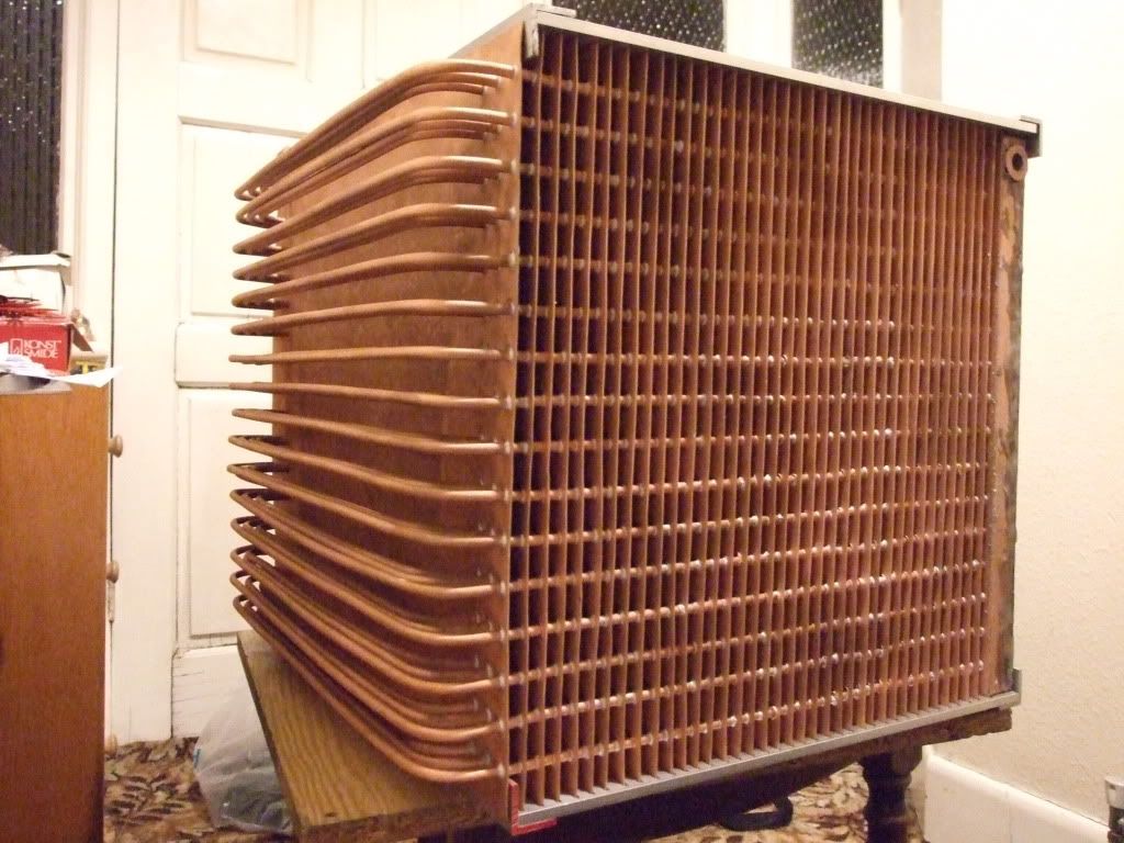
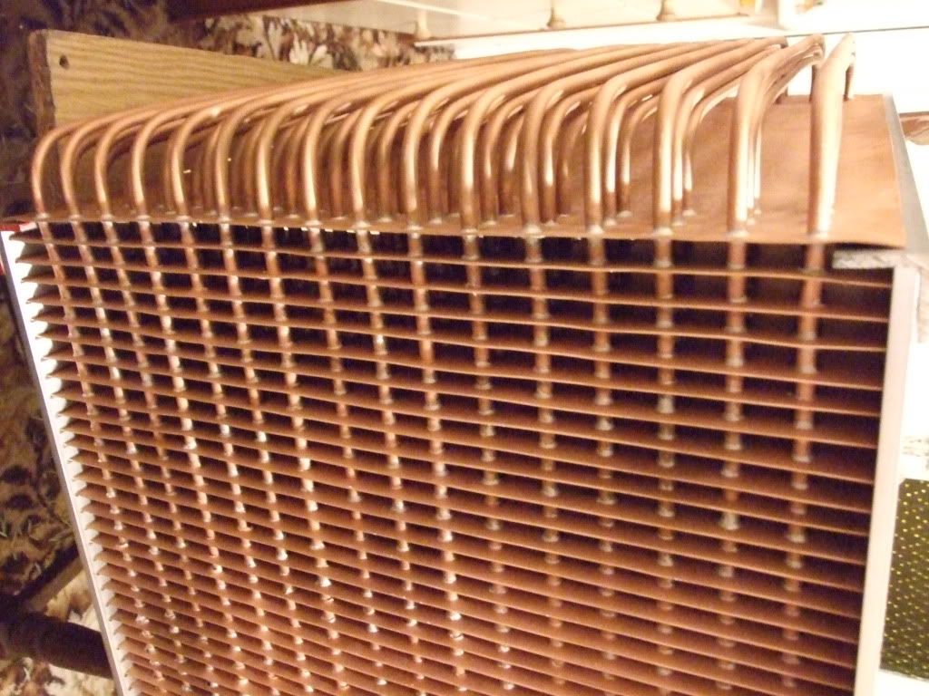
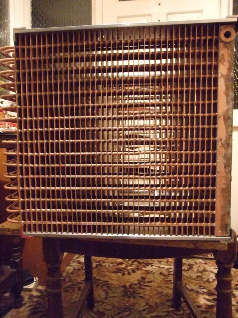
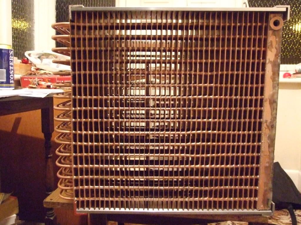
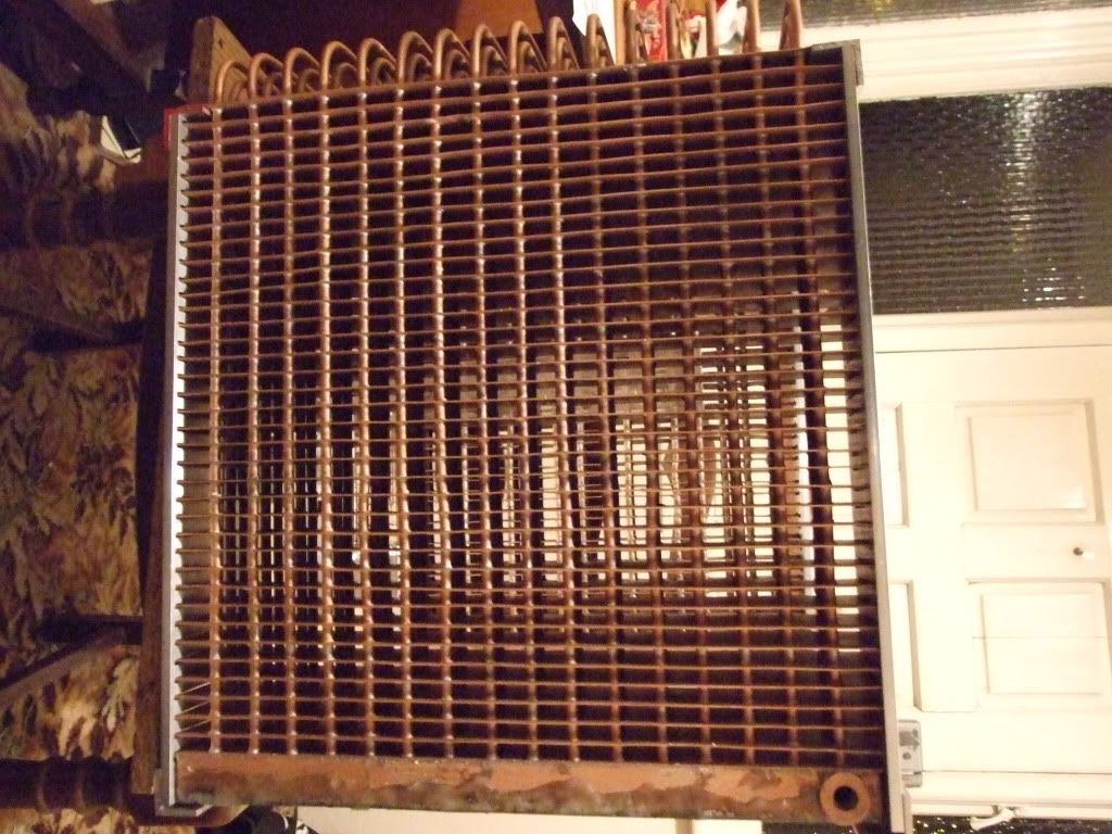
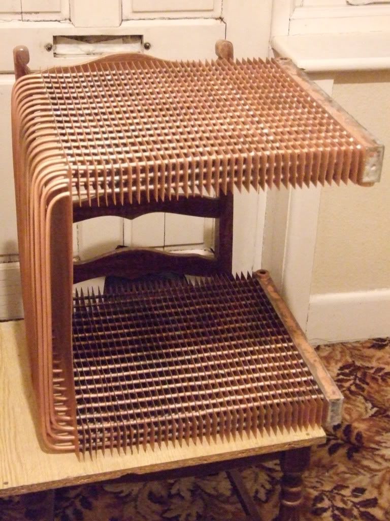
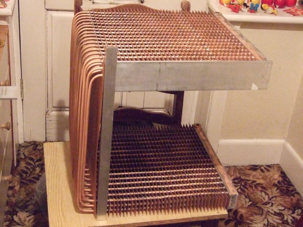
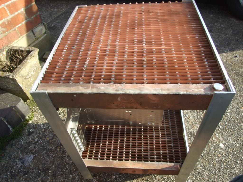
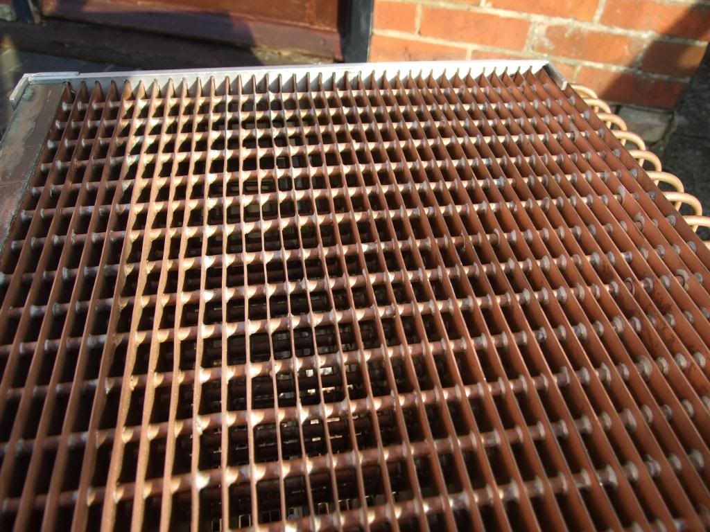
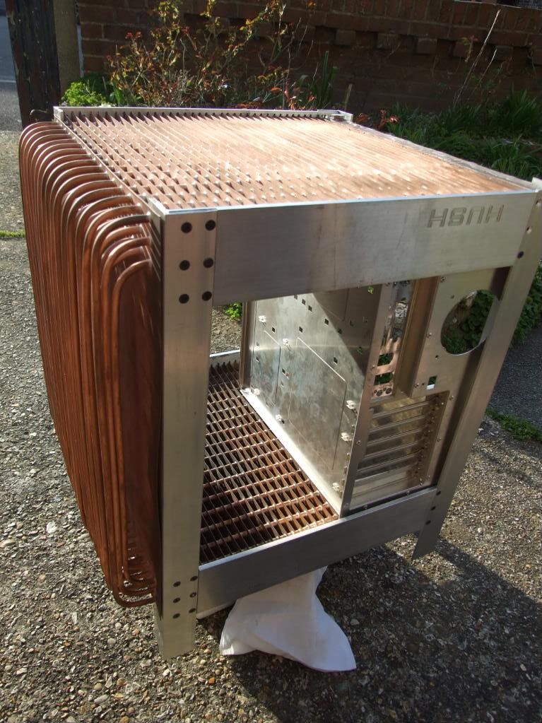
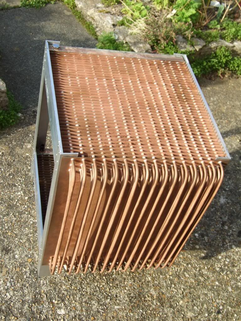
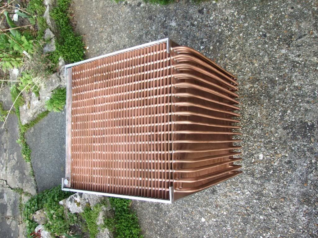
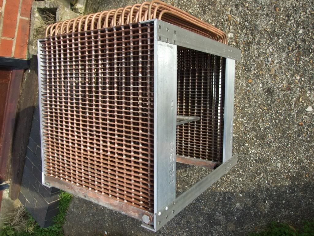
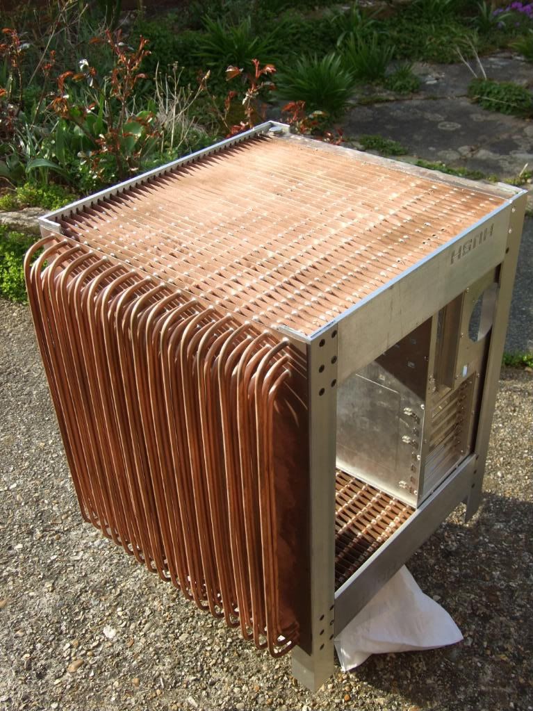
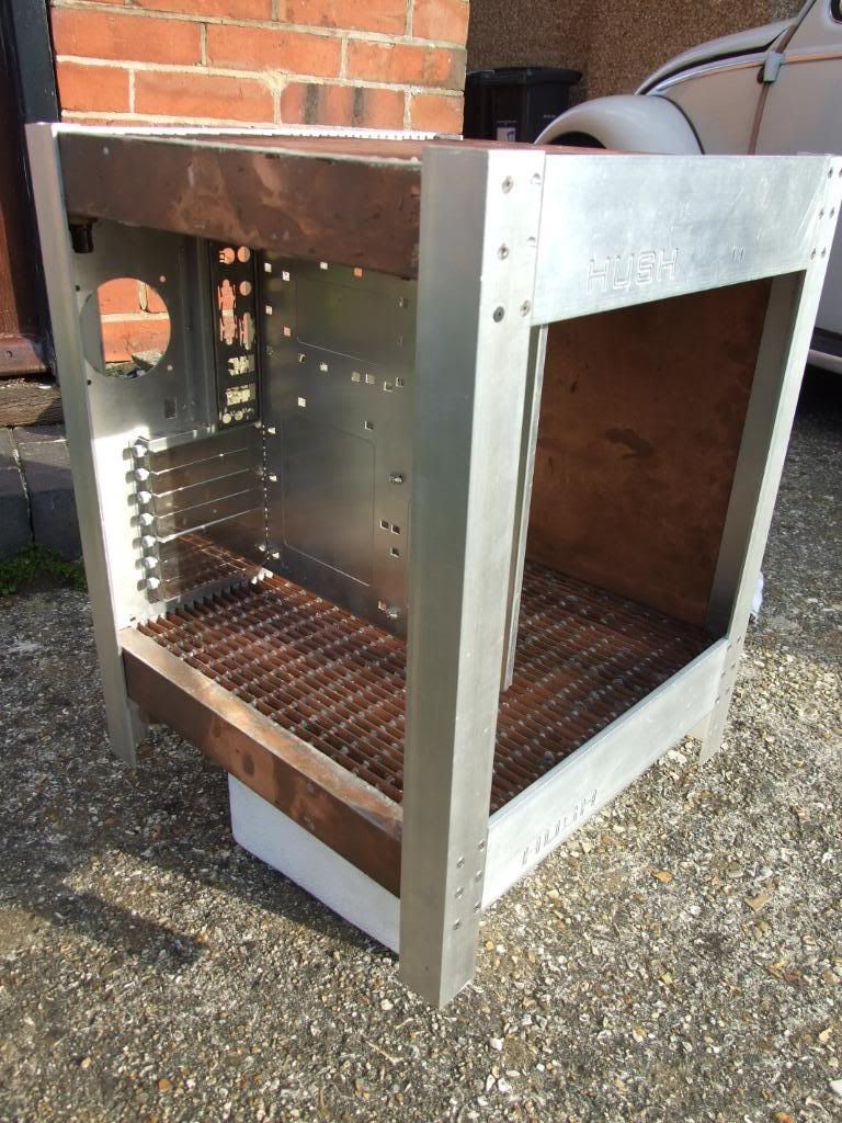
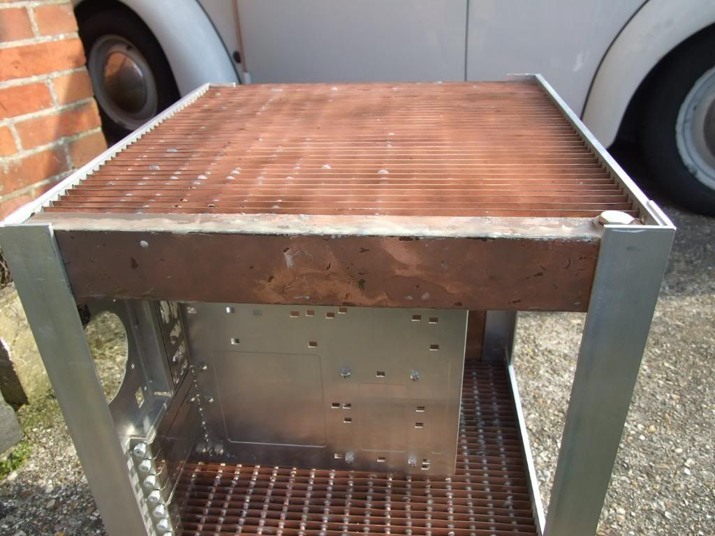
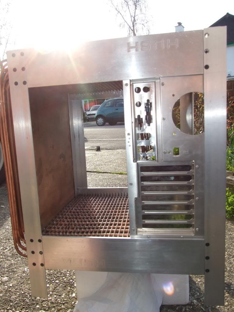
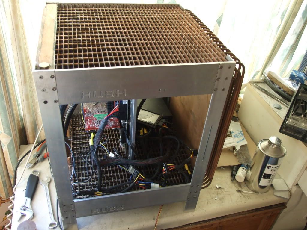
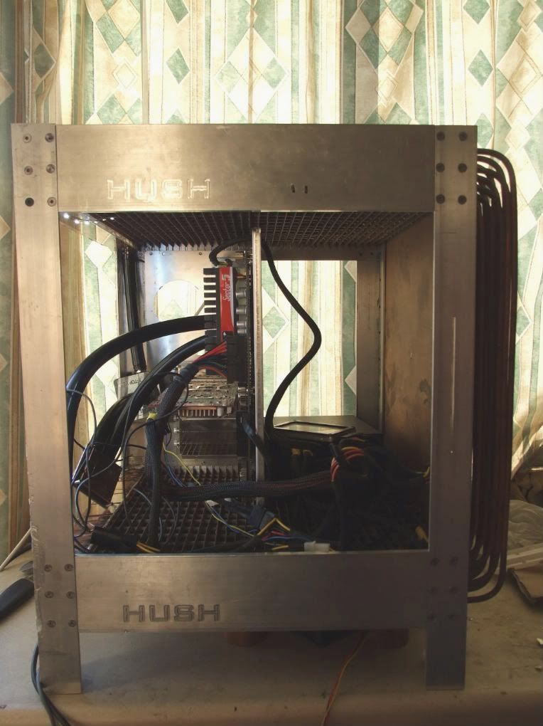
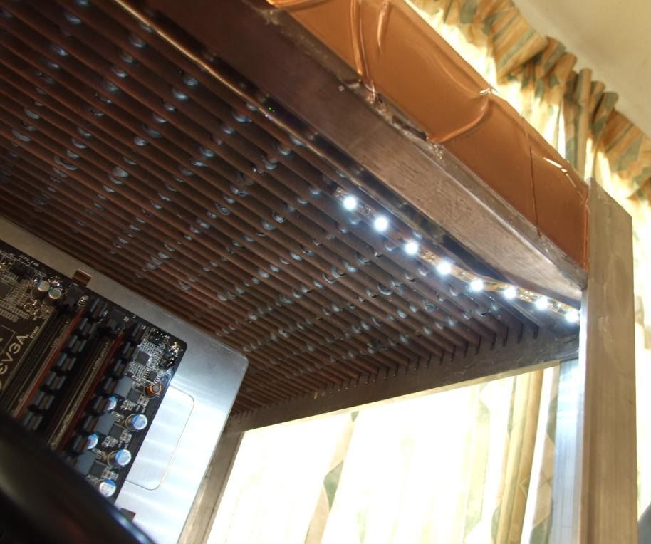
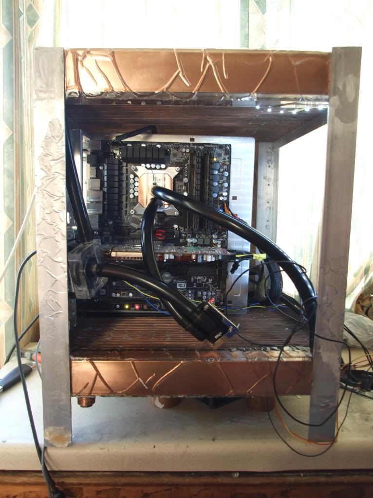
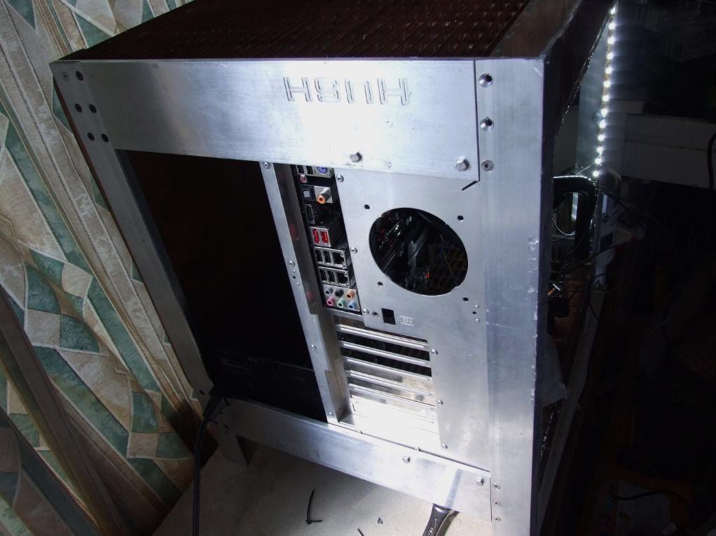
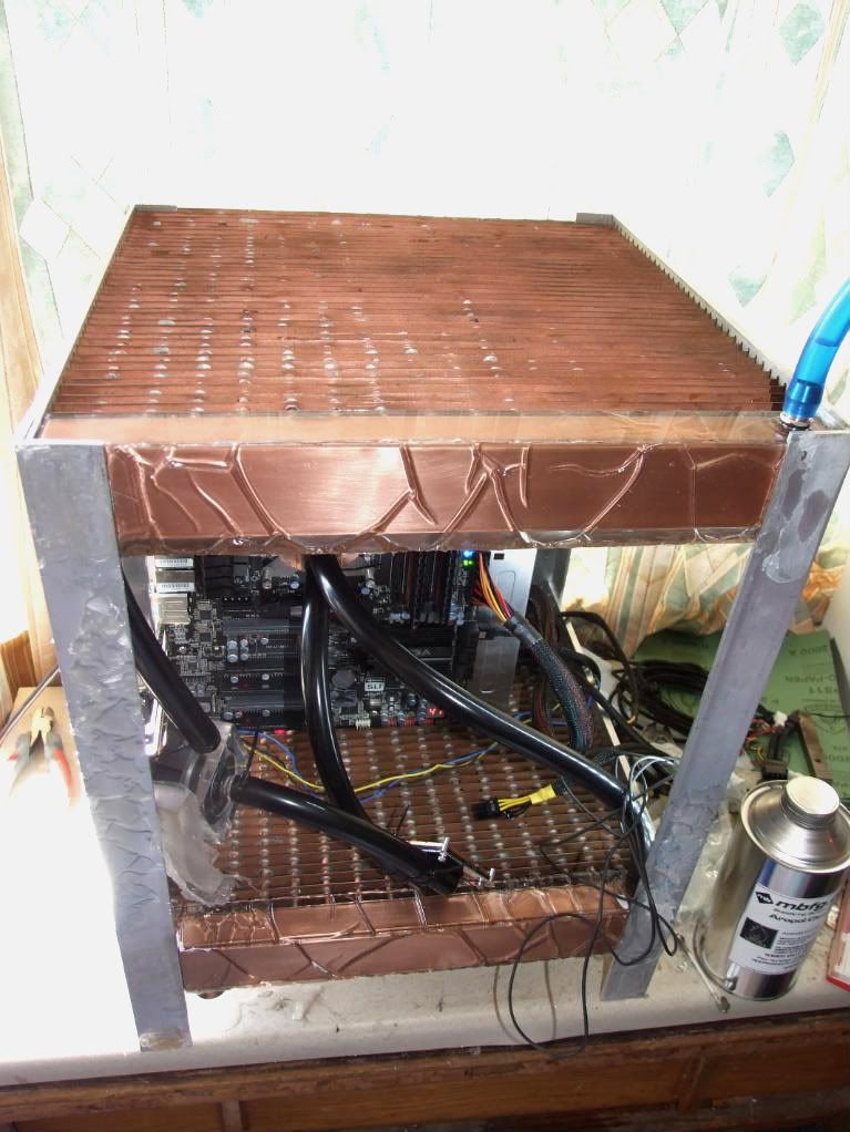
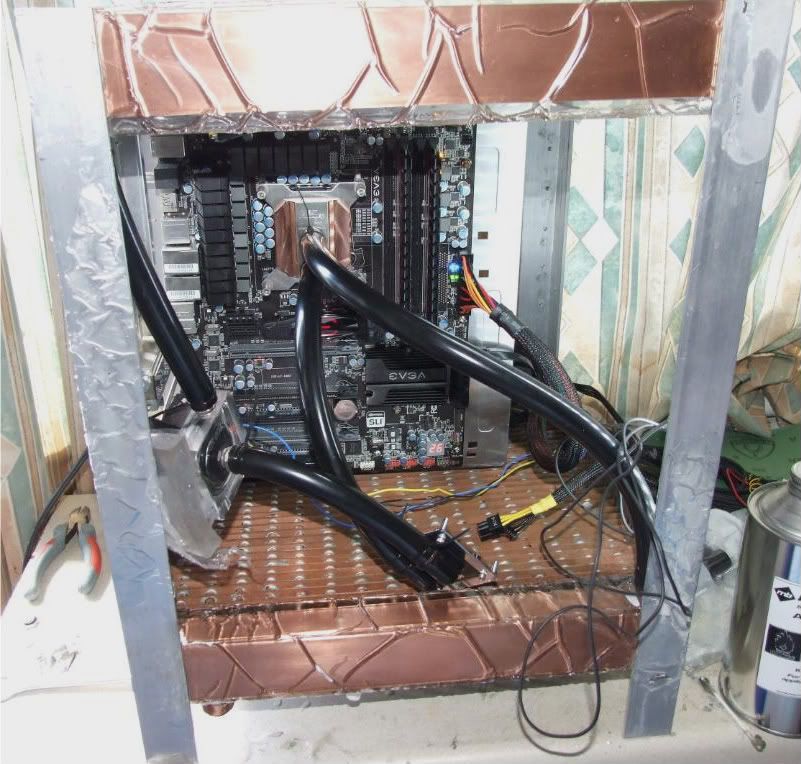
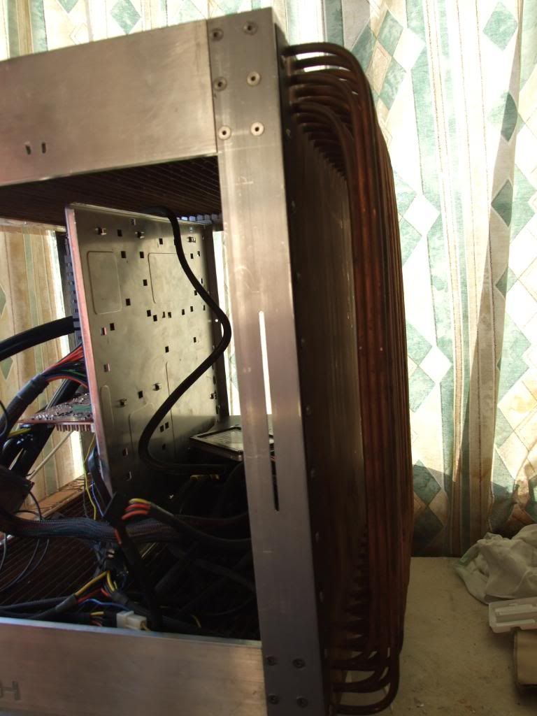
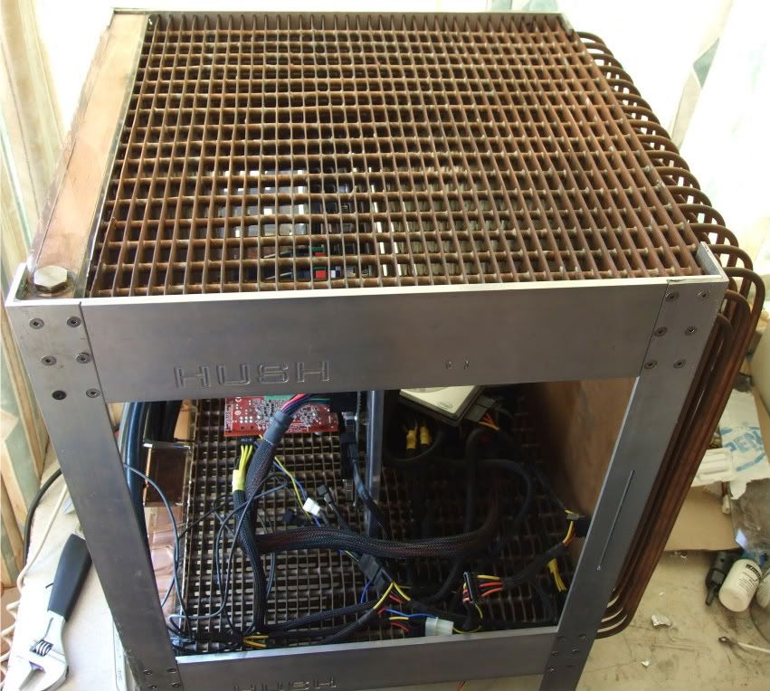
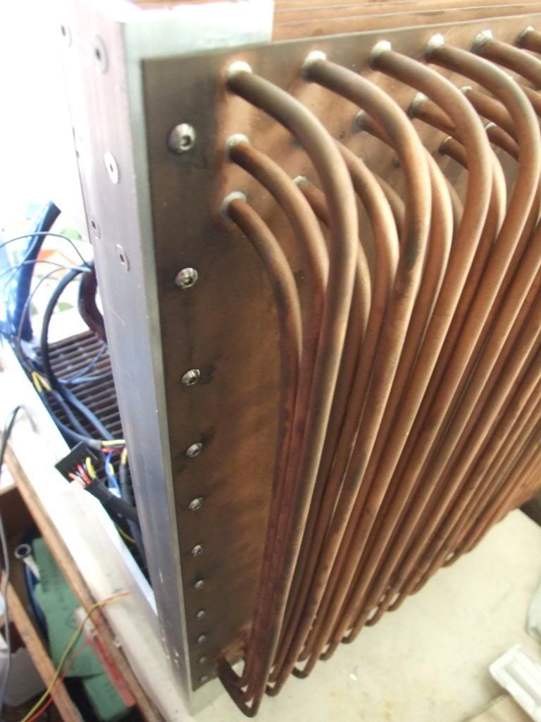
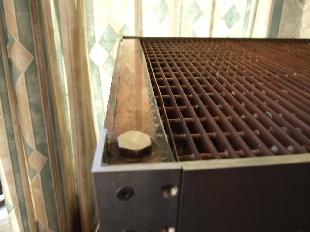
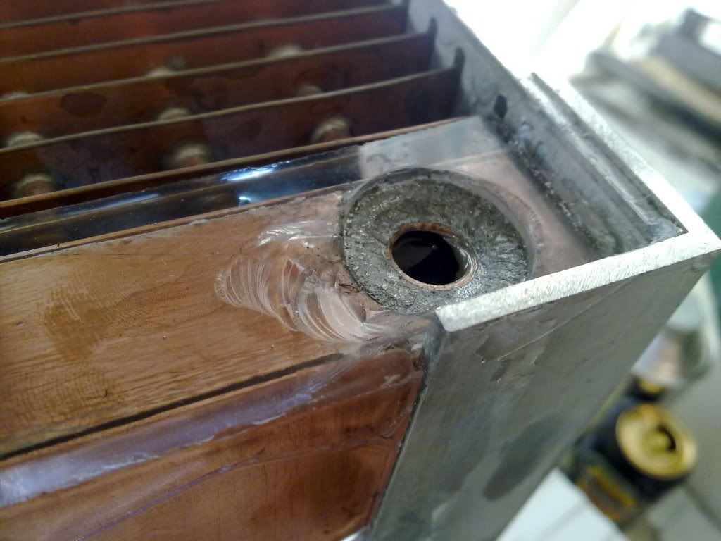
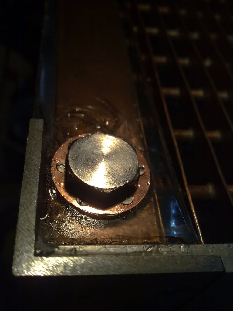
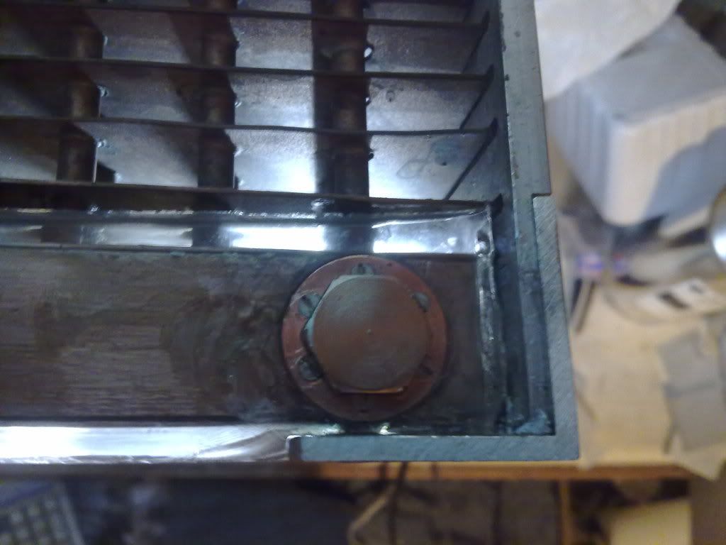
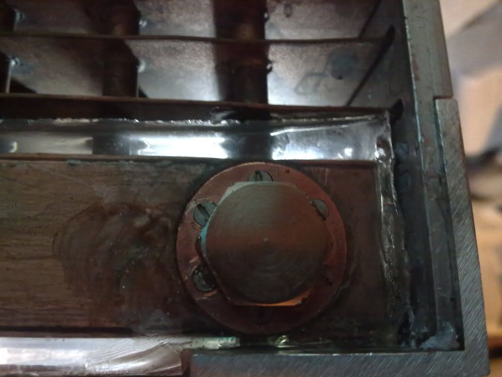
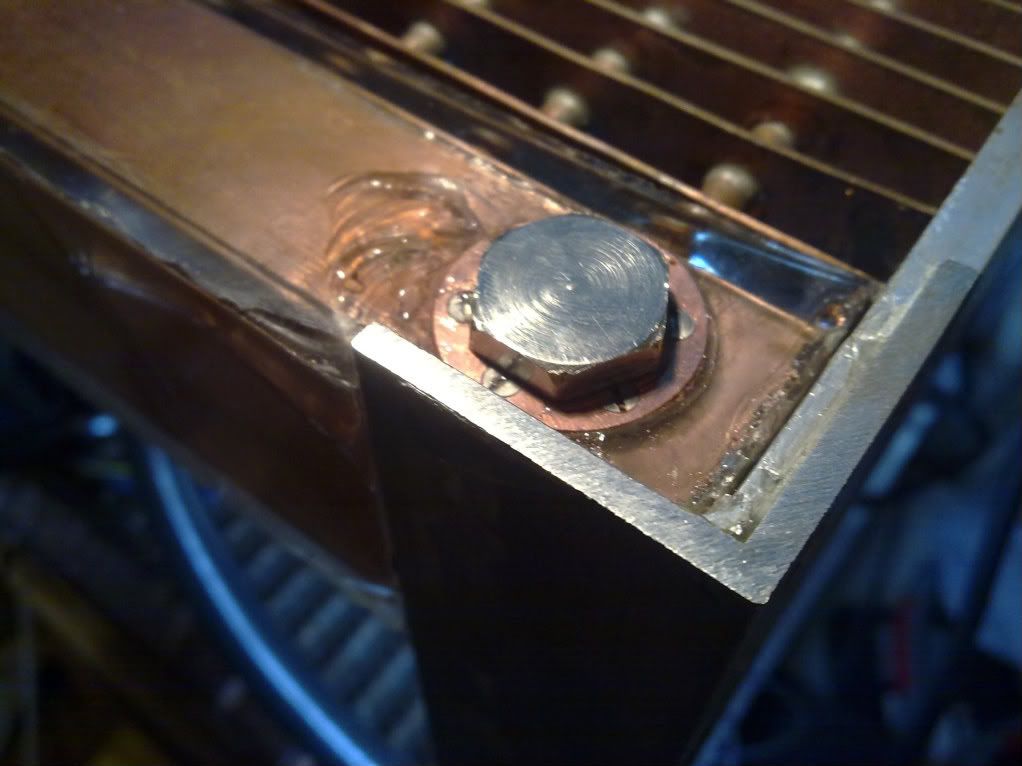
Okay, so for a bit over a year I've been working on building a scratch-built radiator/case for passive-cooling. The idea is for a low-noise solution to running an overclocked machine, and so it's been optimised for passive cooling - the radiator has 2.5 fins per inch and runs fanless. It has a total cooling surface area of just under 43,000cm^2 of copper. For reference, a TRUE has 7,500cm^2.
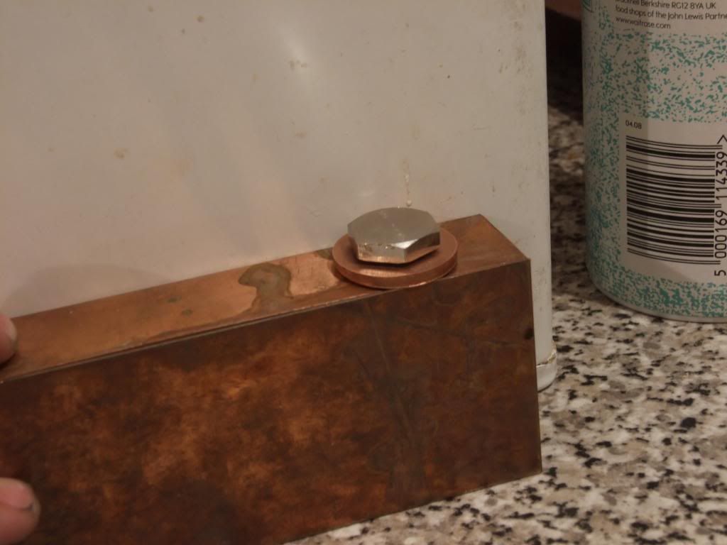
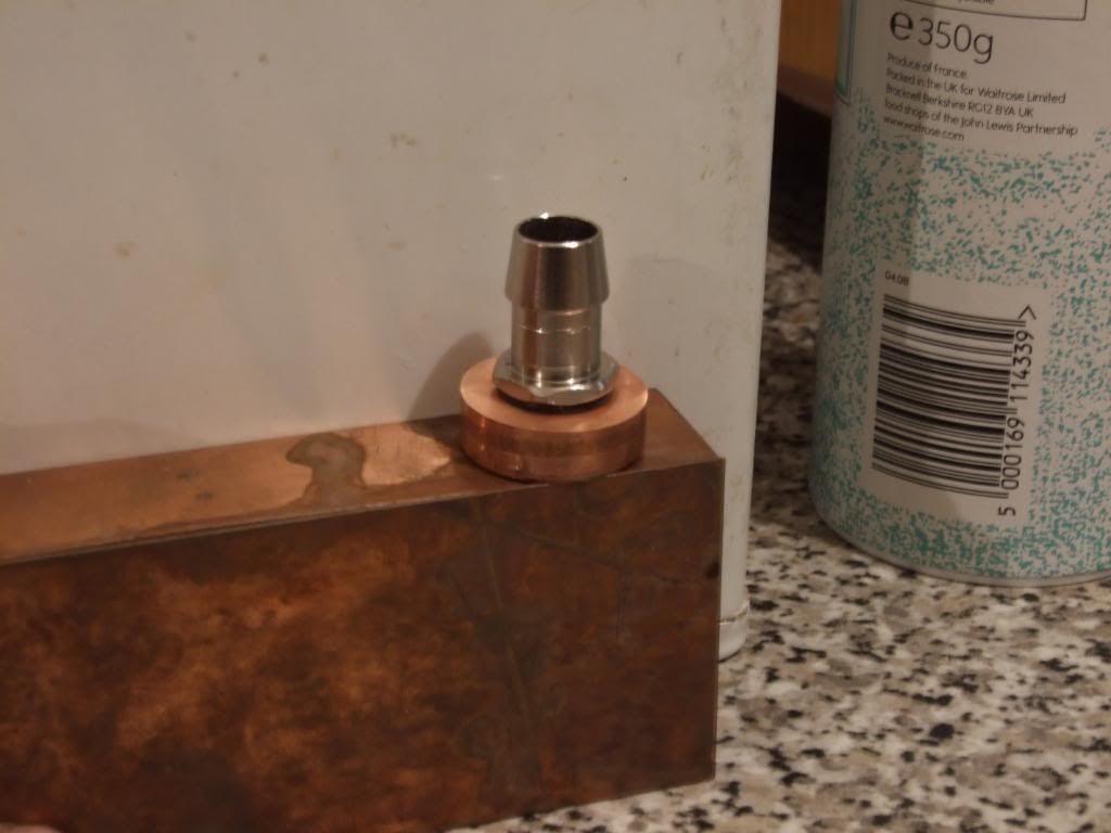
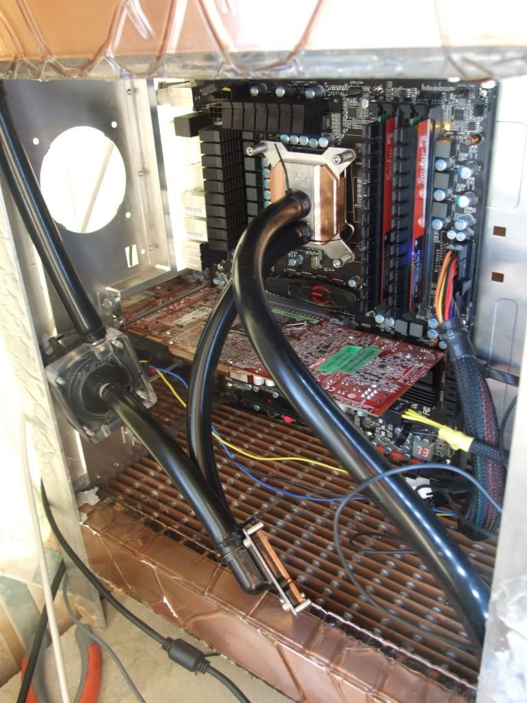
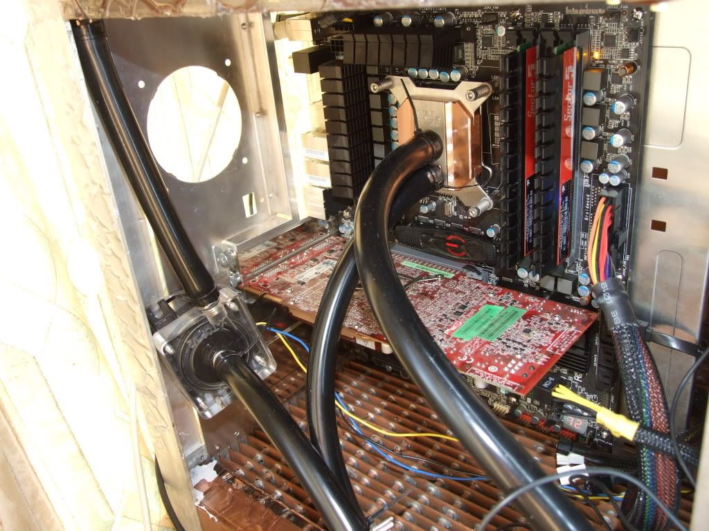
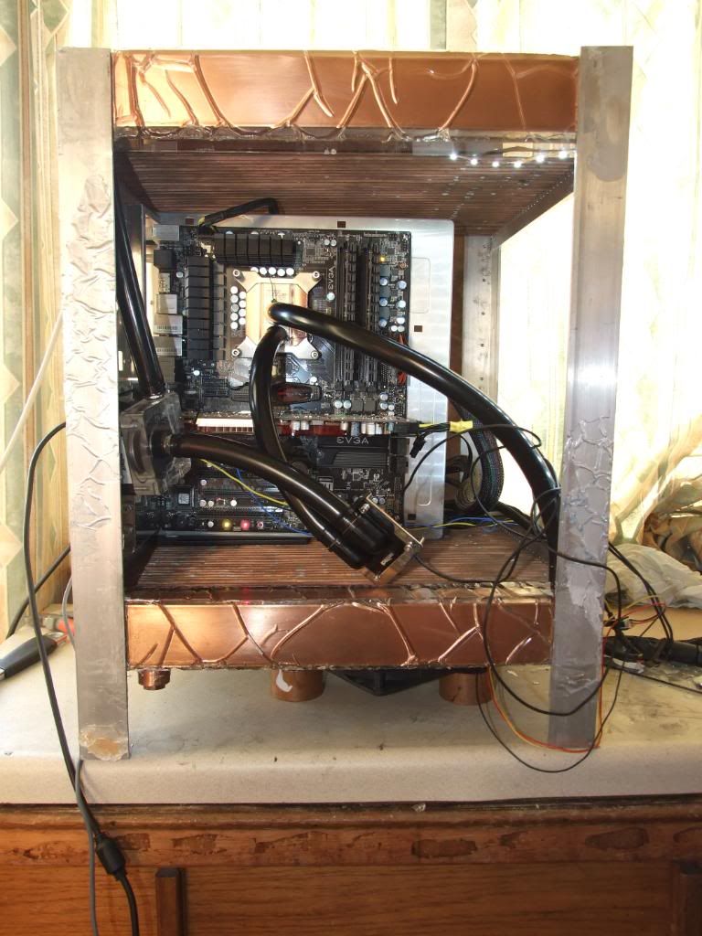
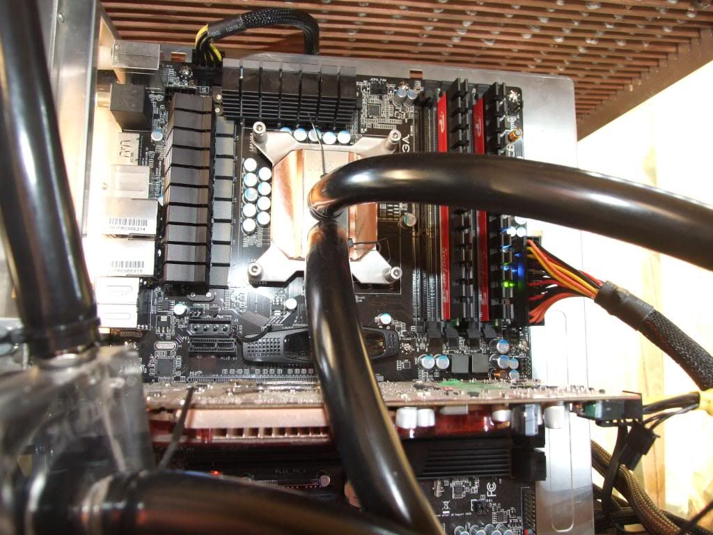
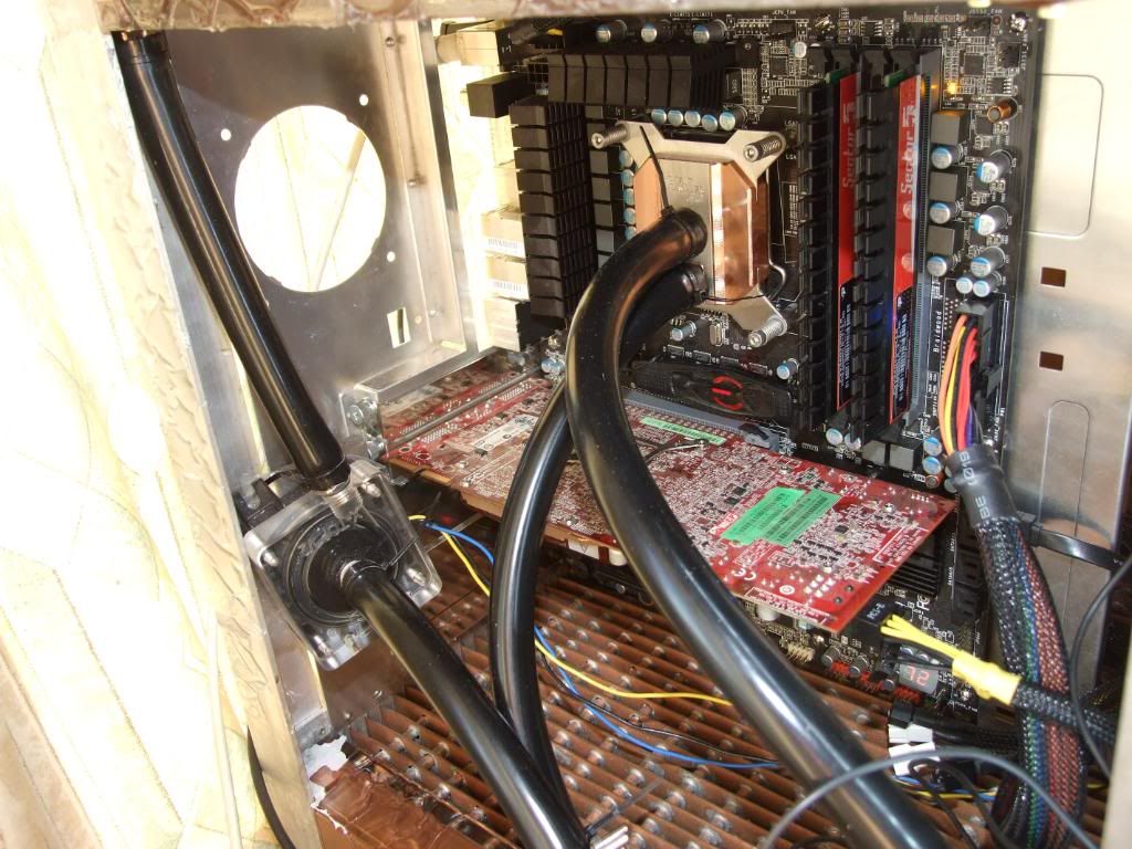
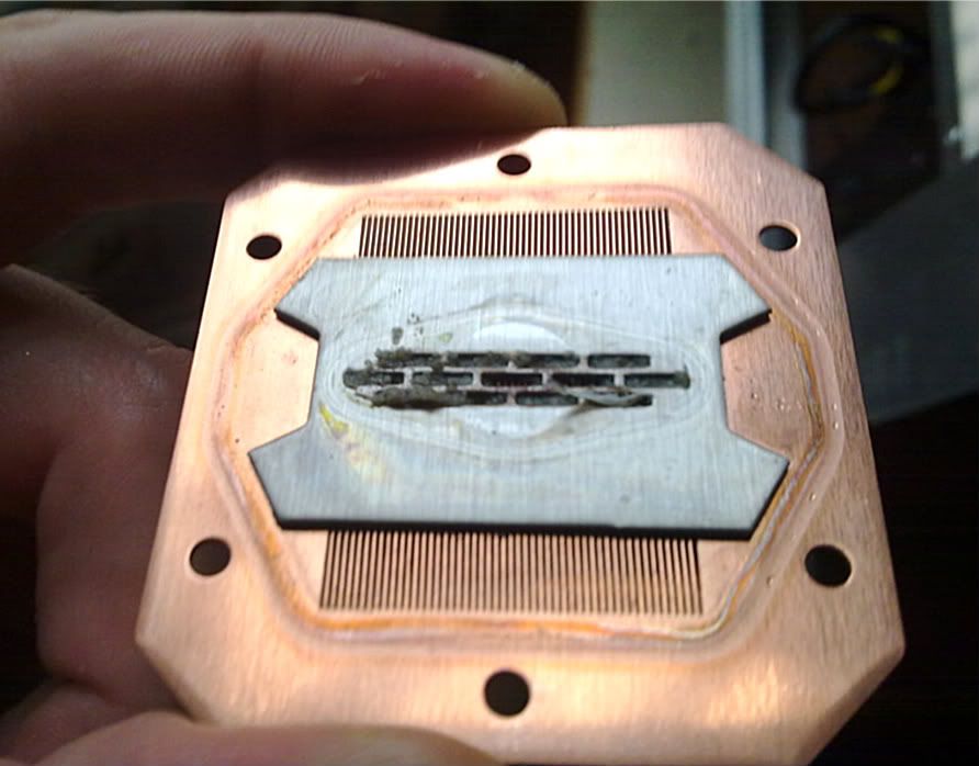
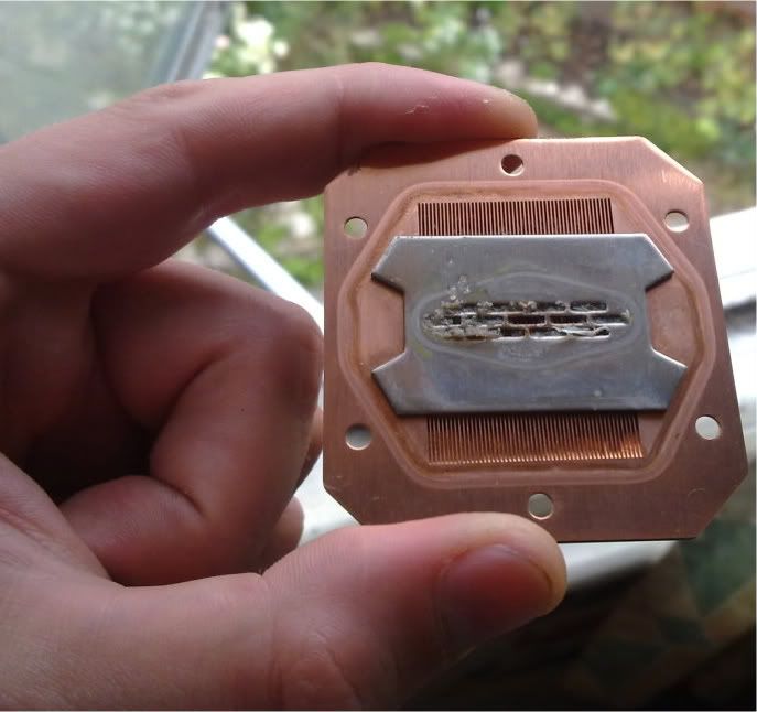
The radiator is currently plumbed up and running my i750 at 4.2GHz (1.43vcore) and 4850 GPU with a Heatkiller 3.0 block and an MCW-60, with an 18w DDC pump with XSPC top and 1 metre of ½ tubing. Temps are pretty good runs around 30C idle on the CPU and gets to around low 50s C gaming. Not sure of ambient temps; standard indoors of around low 20s celcius I expect need to get some temperature probes and do some proper testing.
The posts below are adapted from progress updates along the way over the past year from several other forums, so they may contain info and plans thats amended along the way. They should be reasonably clear, but as Ive just pasted the updates and not replies explaining bits about it some bits may be unclear. If thats the case please ask and Ill explain.
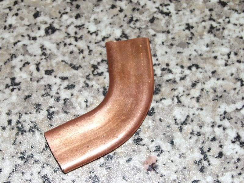
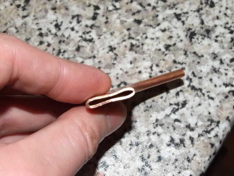
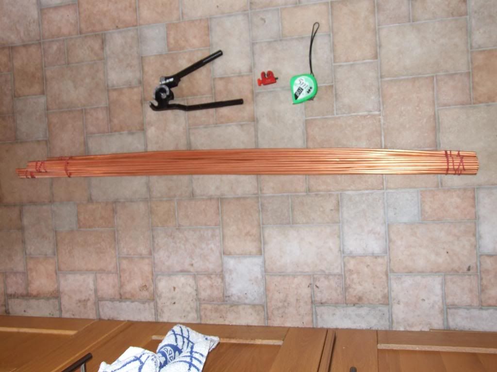
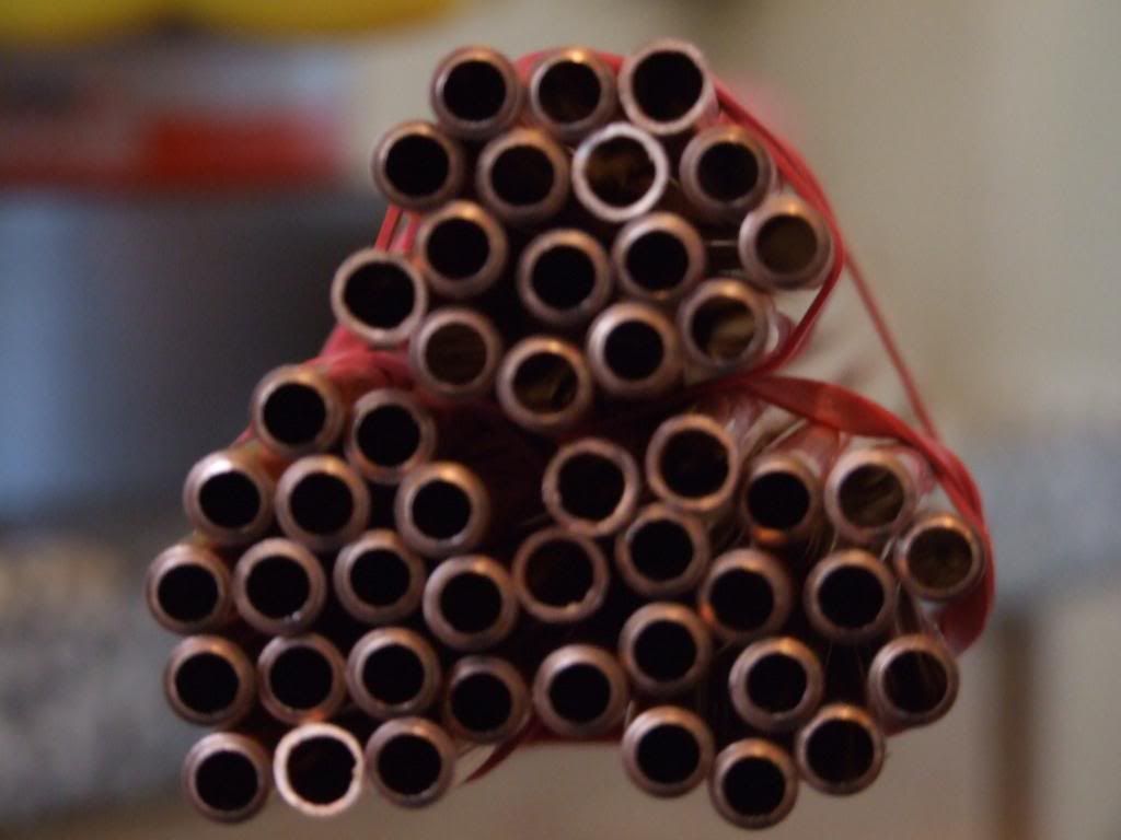
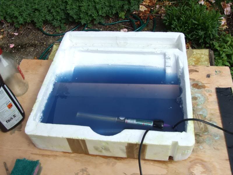
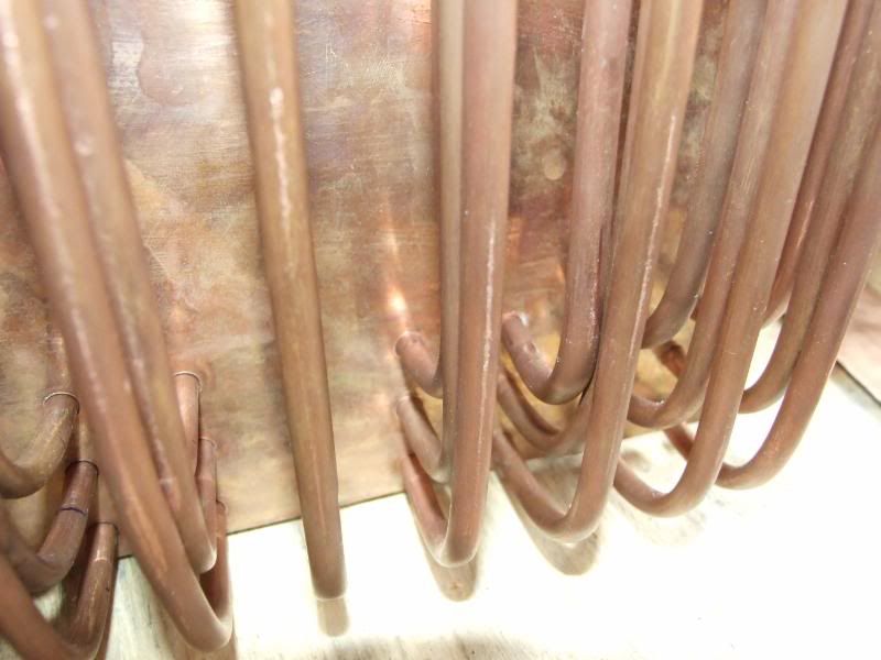
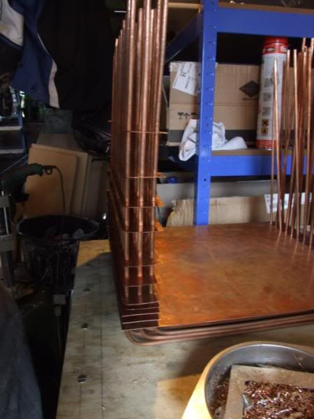
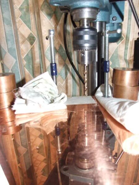
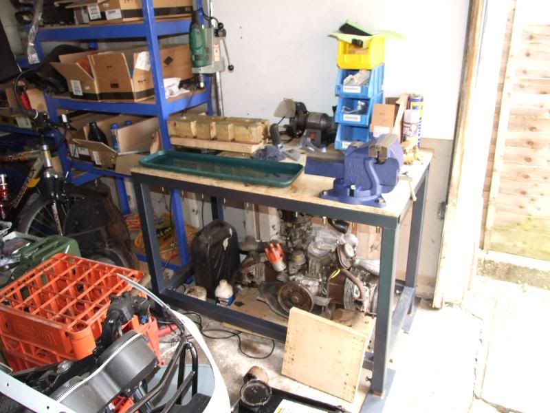
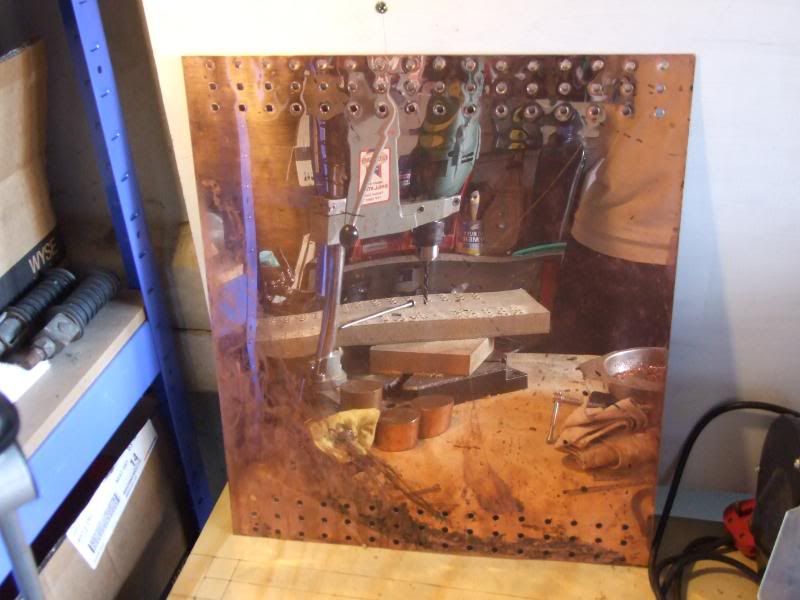
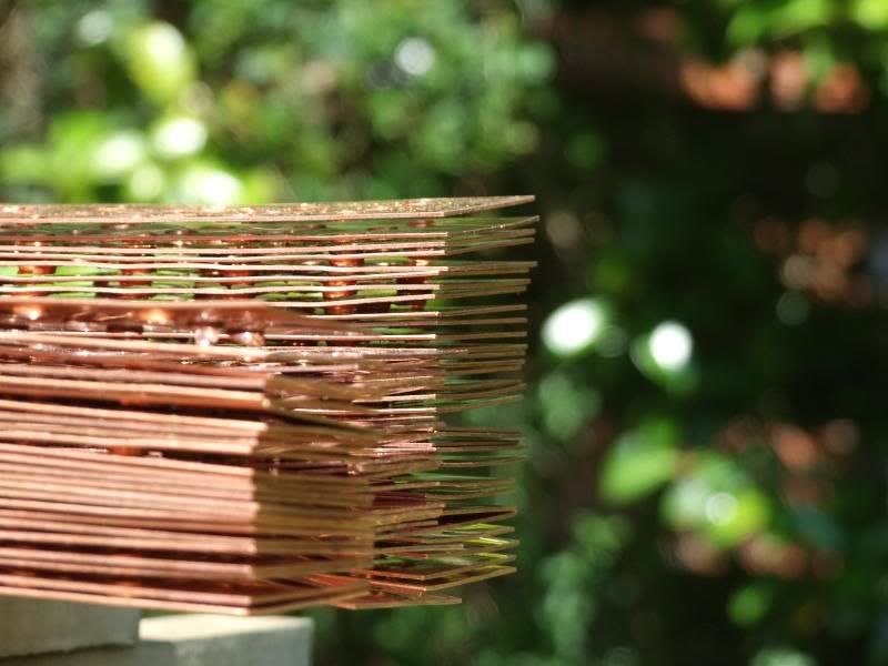
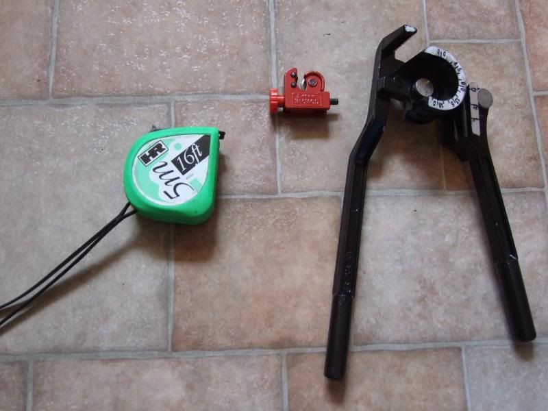
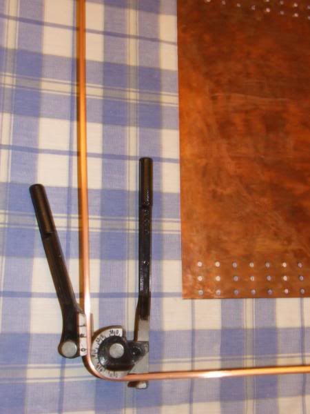
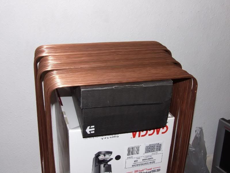
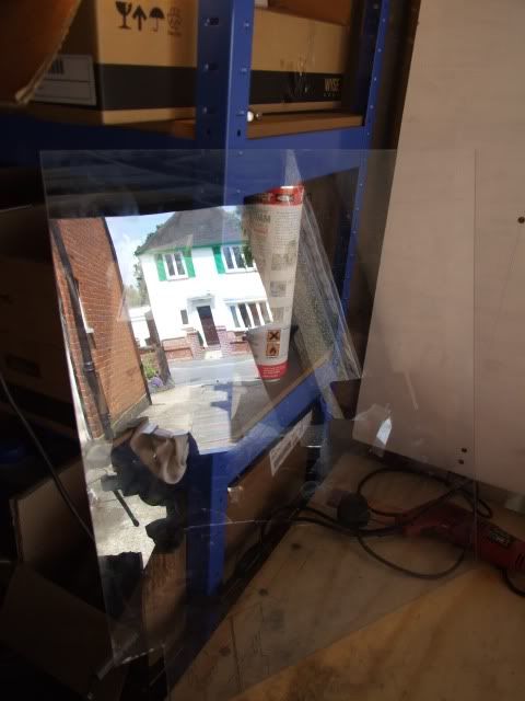
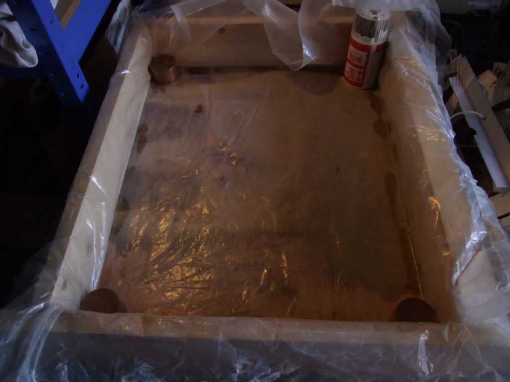
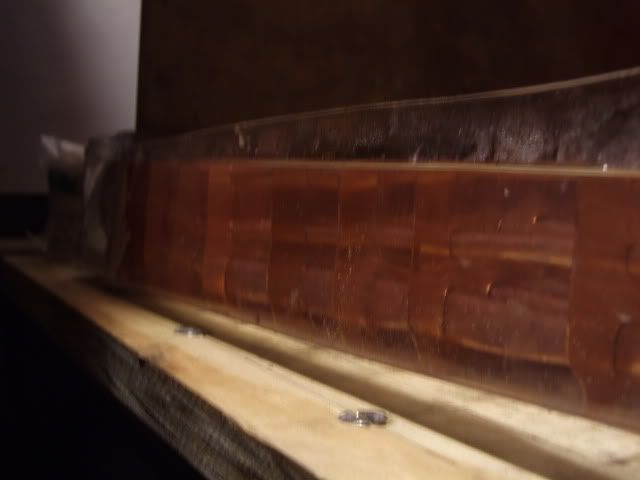
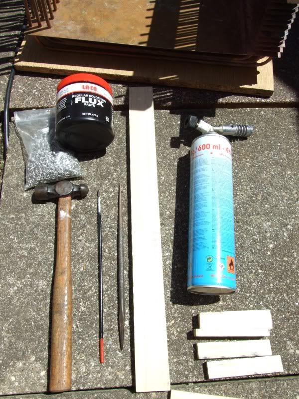
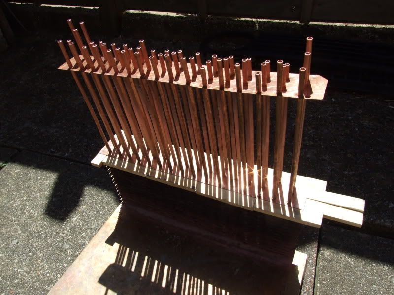
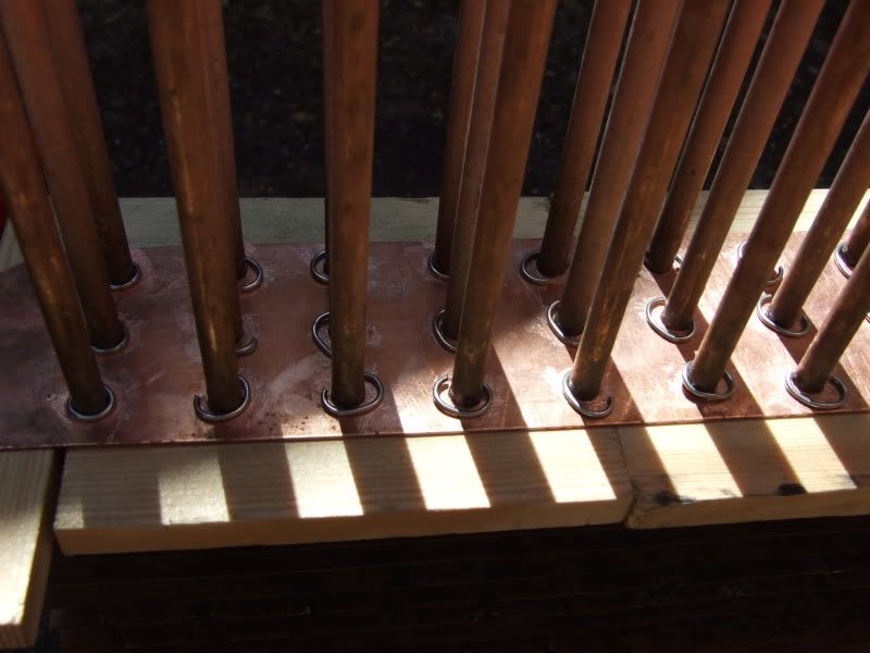
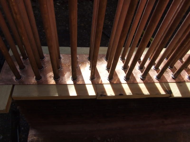
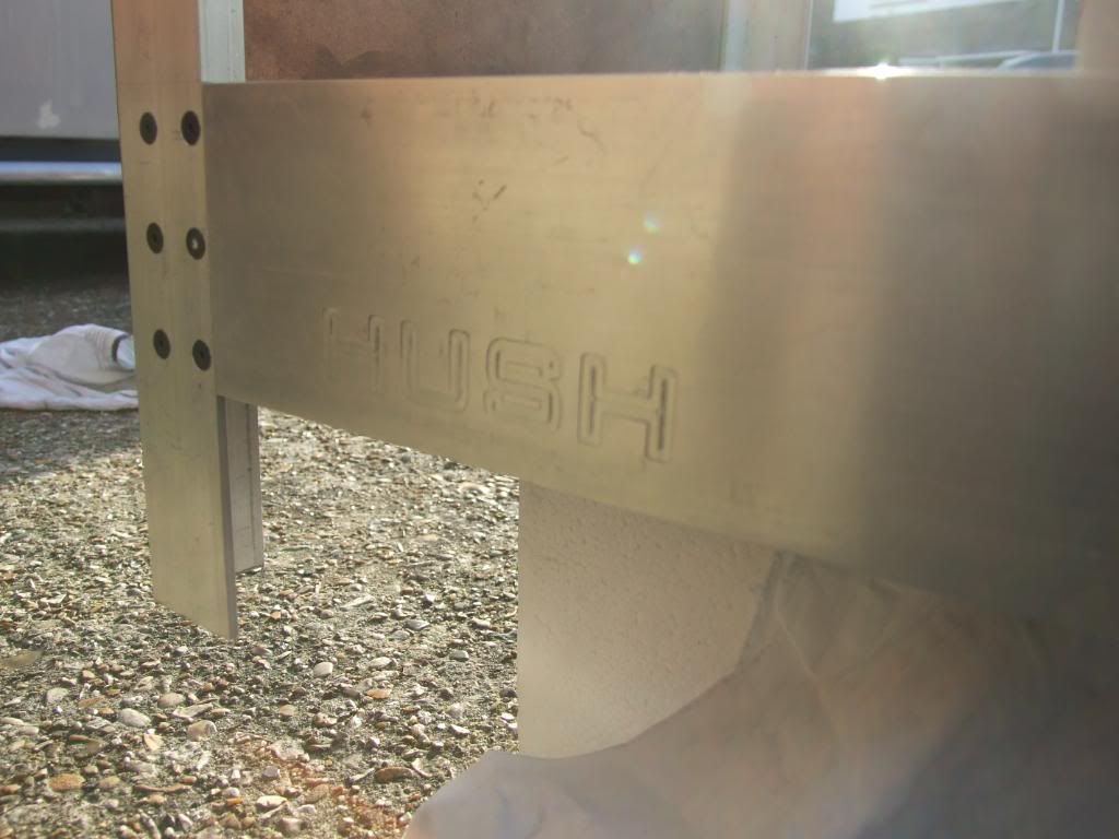
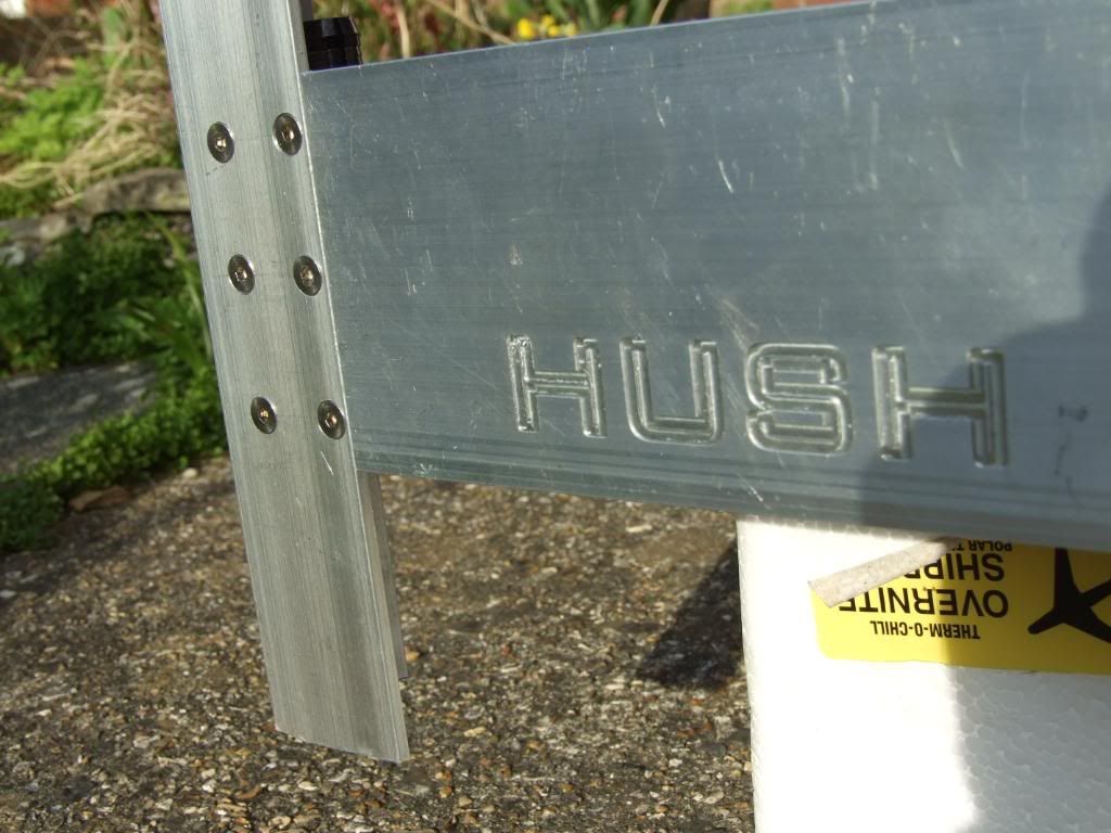
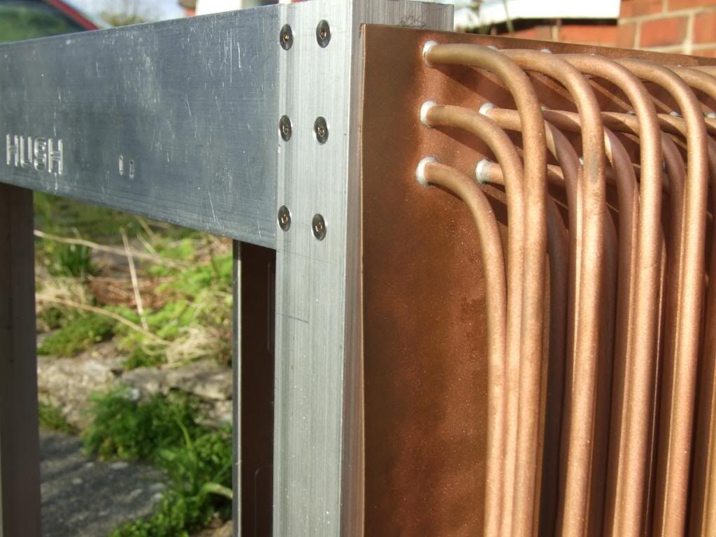
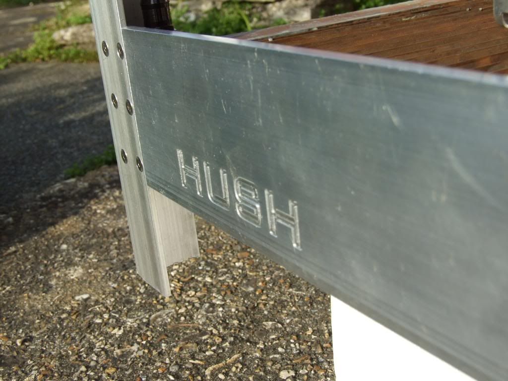
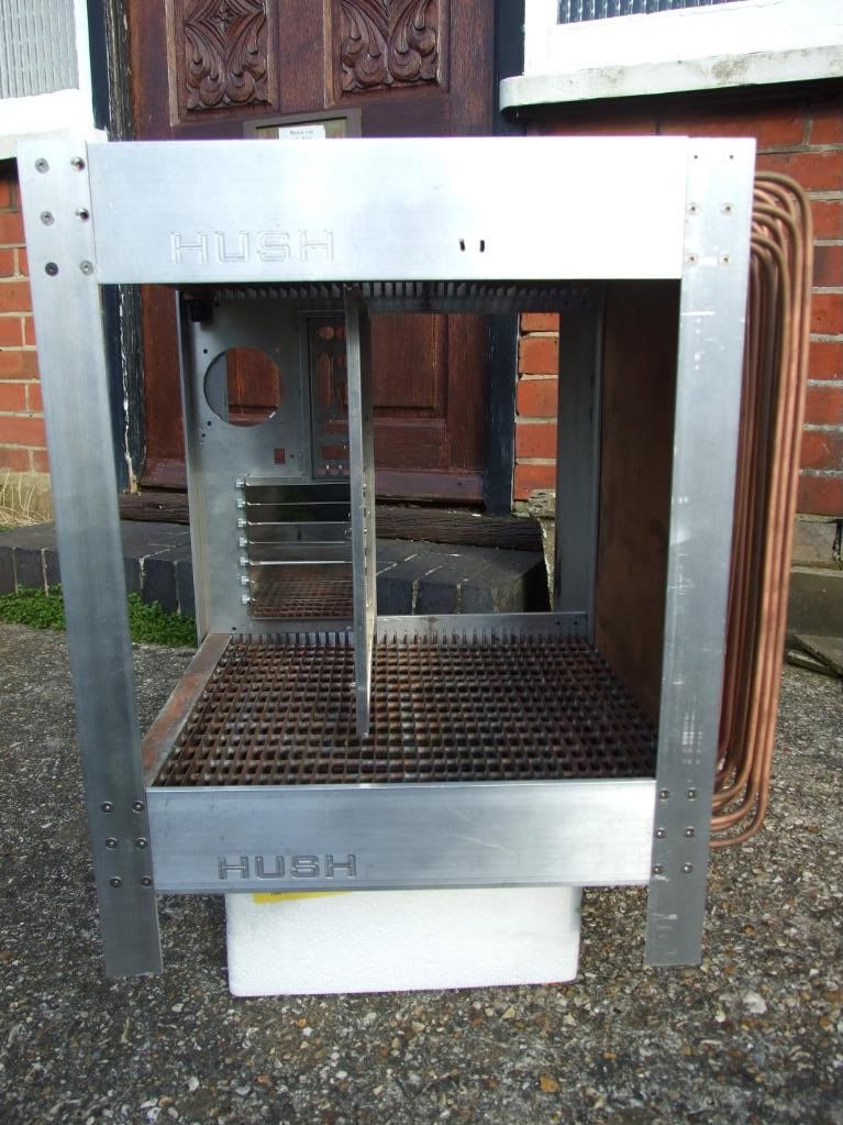
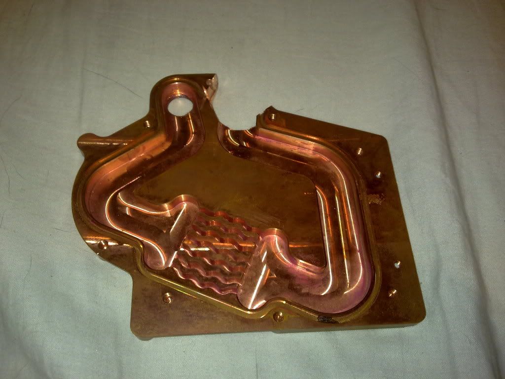
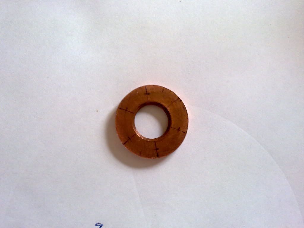
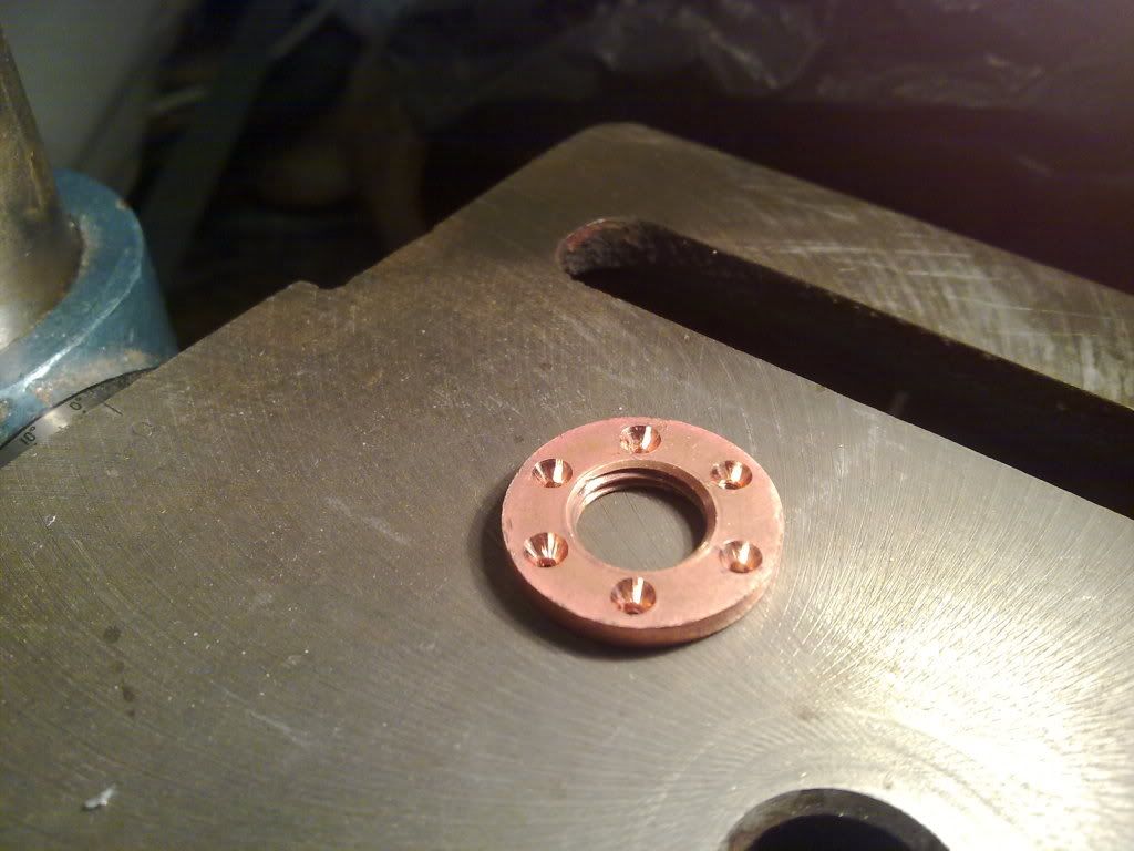
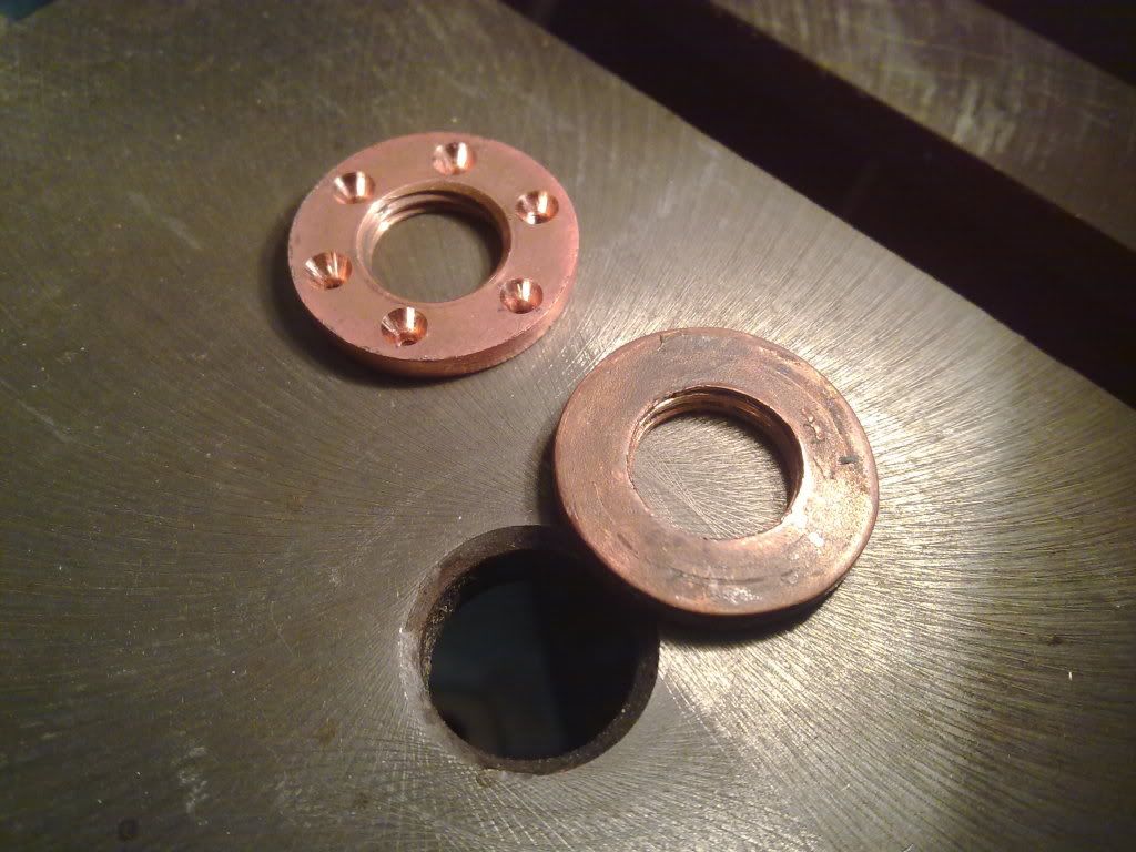
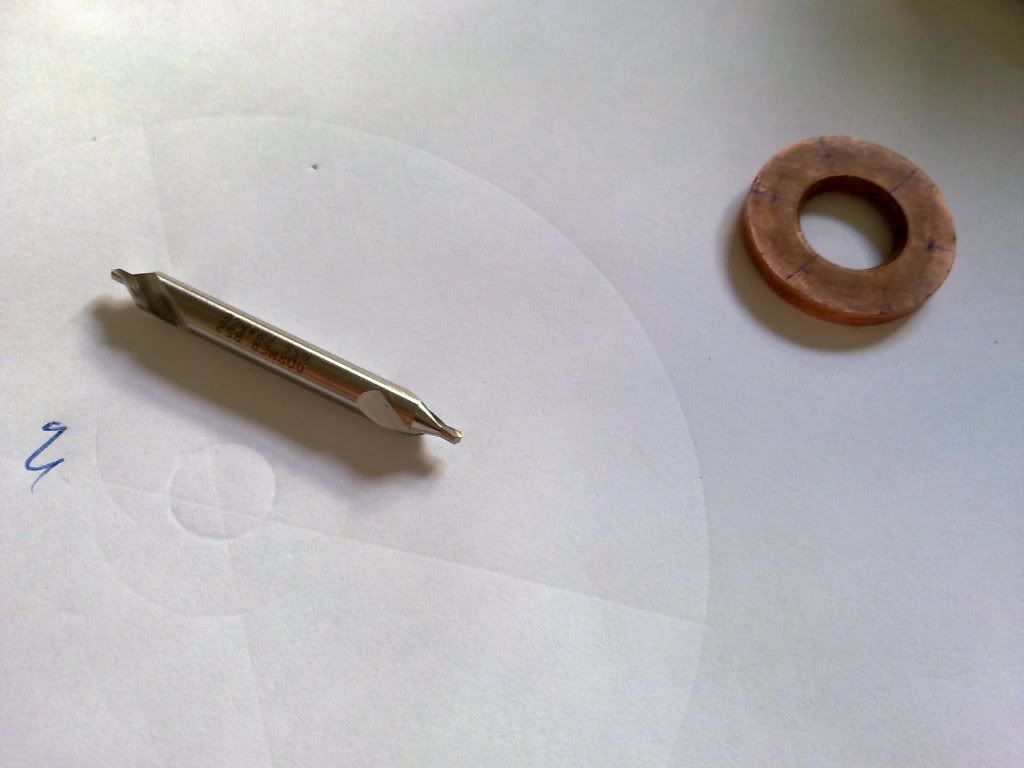
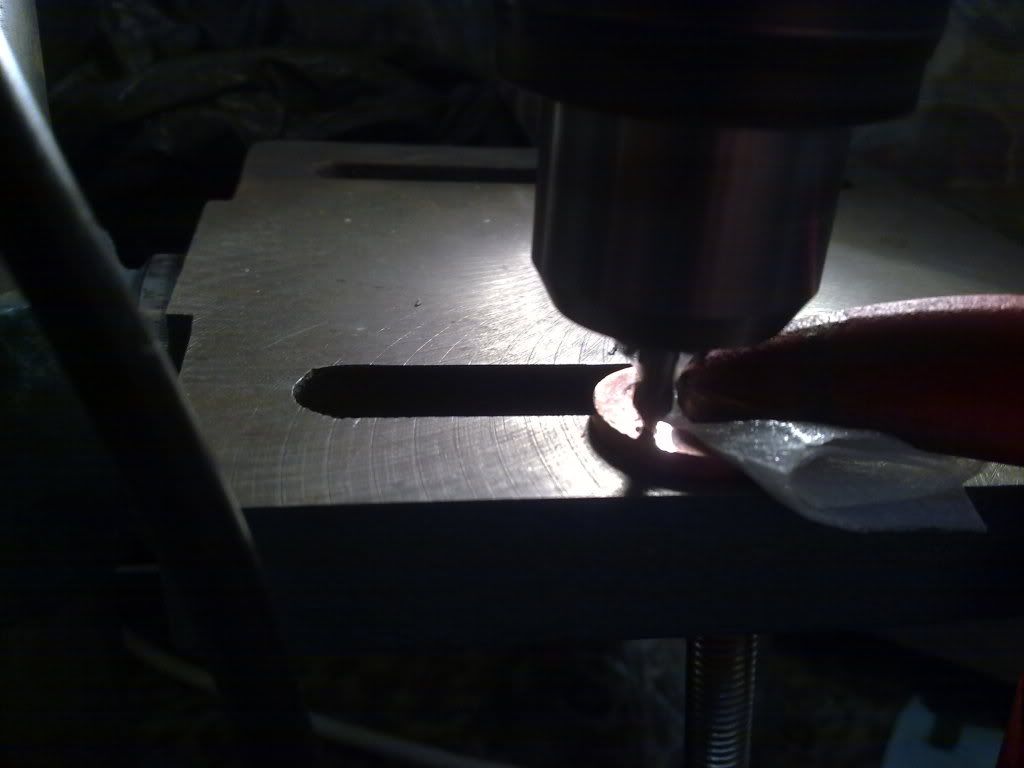
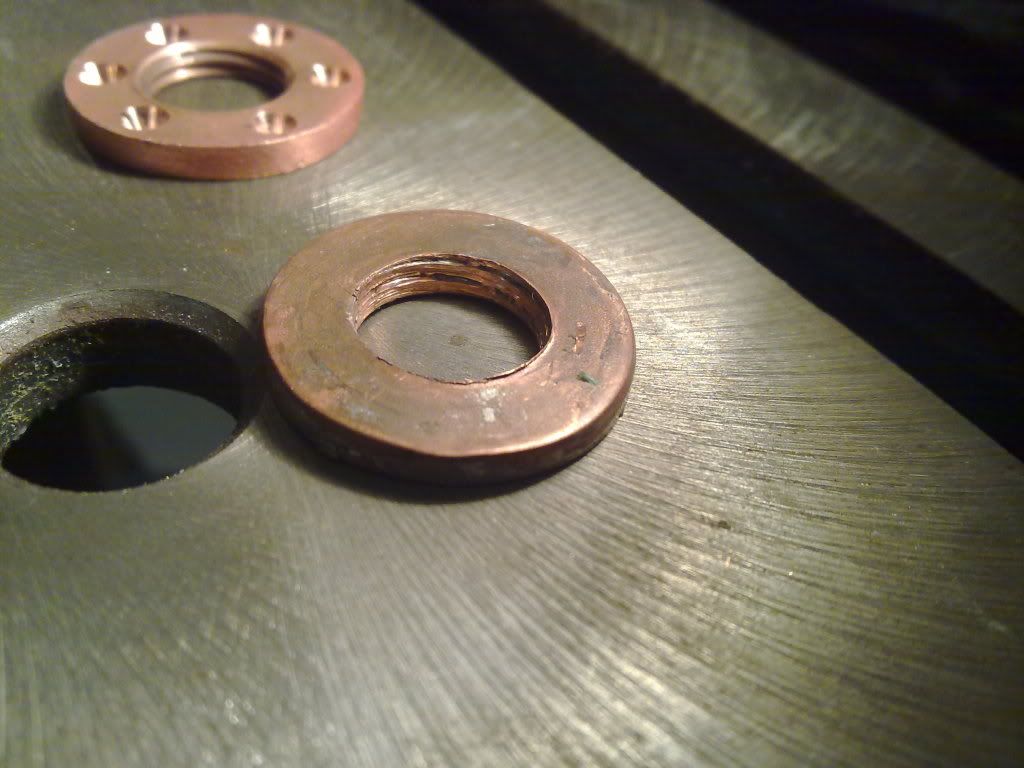
Here's some teaser pics:
Taster pics:
Hope you enjoy the read. Input and suggestions welcome.
----------------------------------------


 Reply With Quote
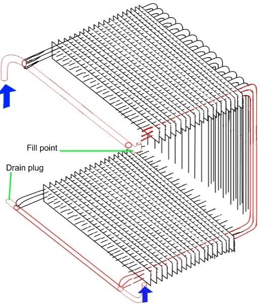
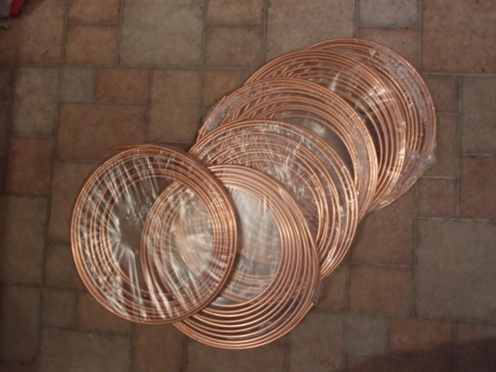
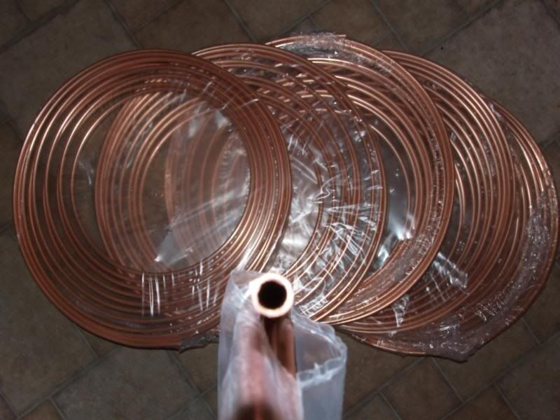
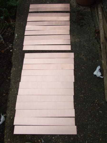
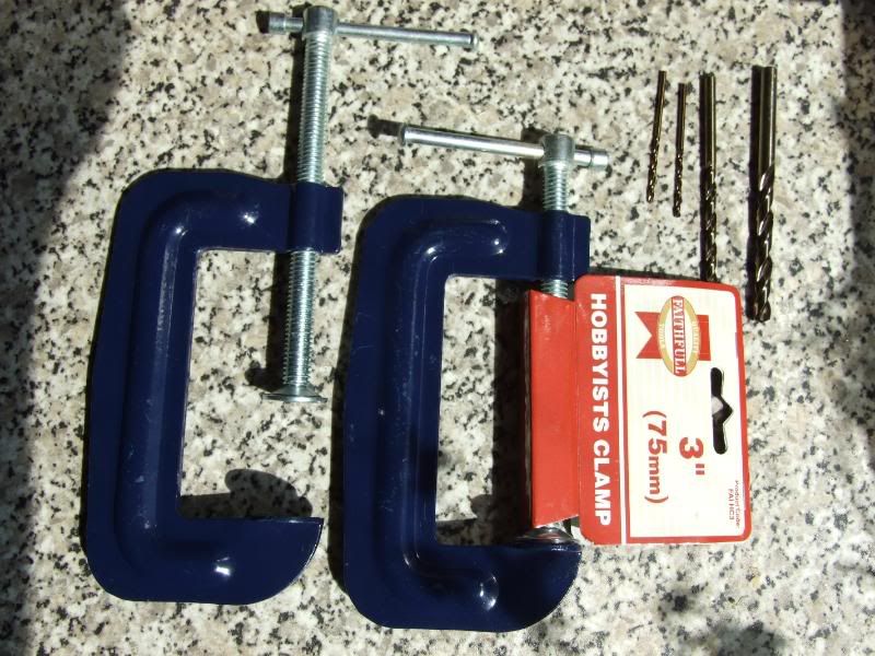
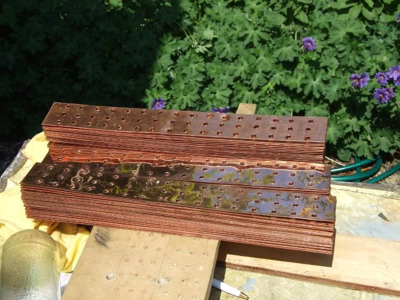
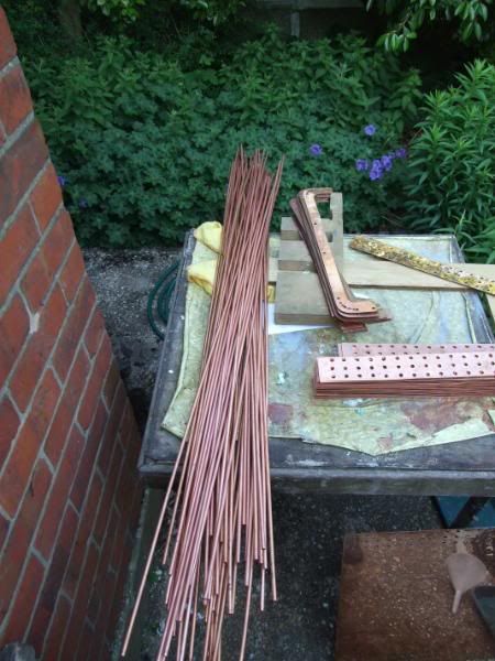
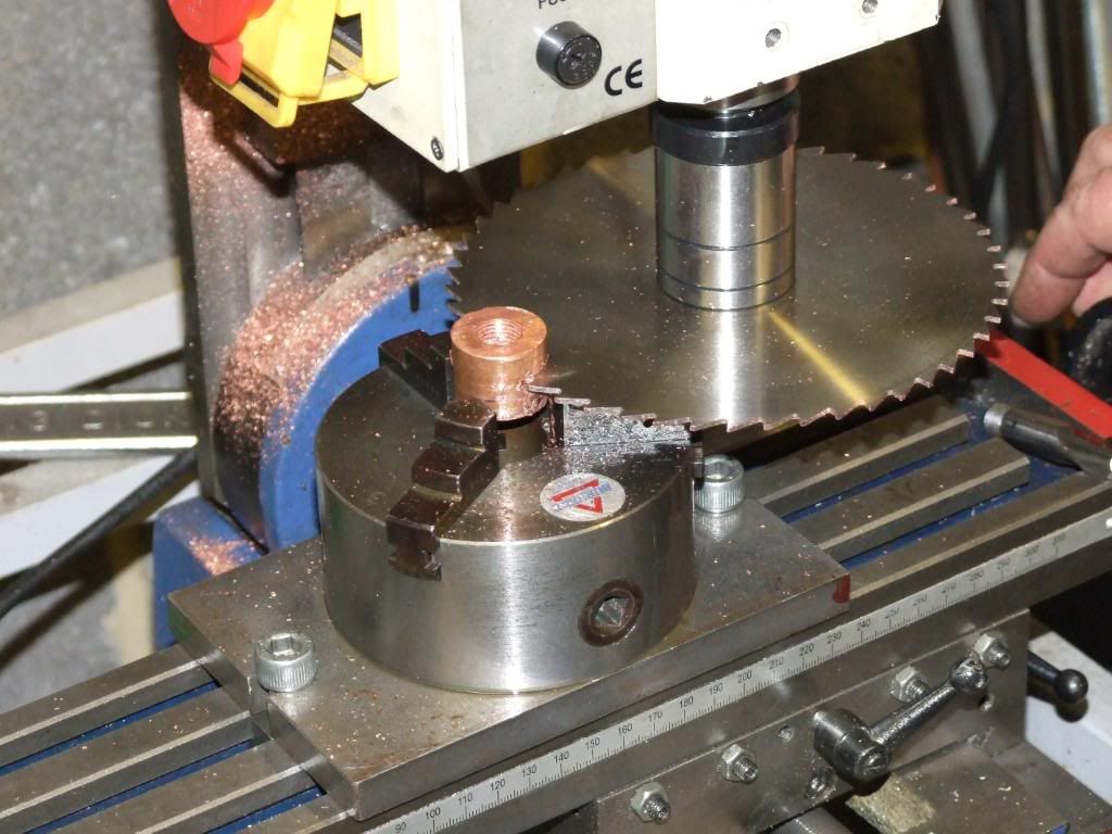
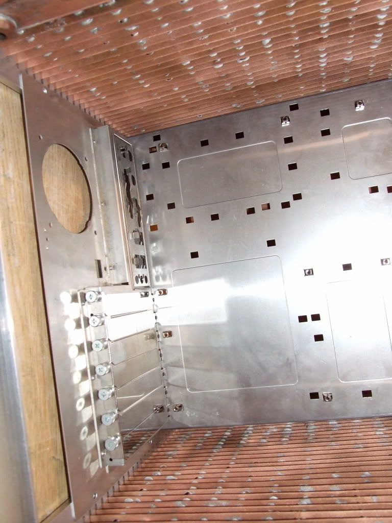
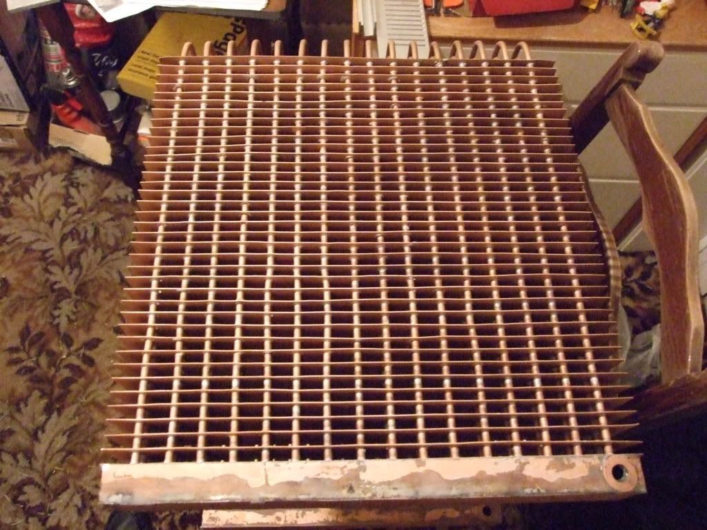
 , and for a small extra charge the seller was even willing to cut it with a metal shear into lots of 395mm x 50mm strips for the heatfins.
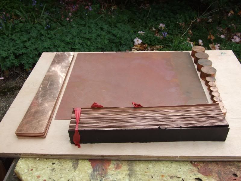
 [/QUOTE]
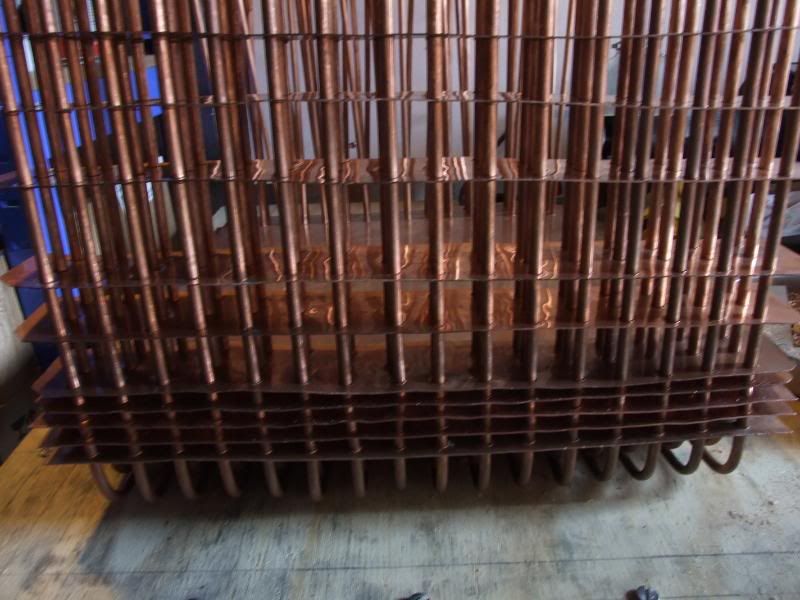
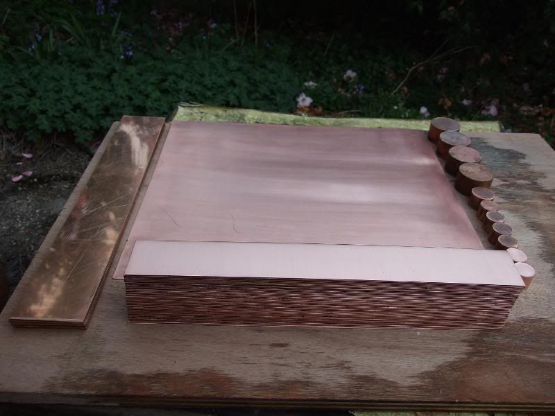
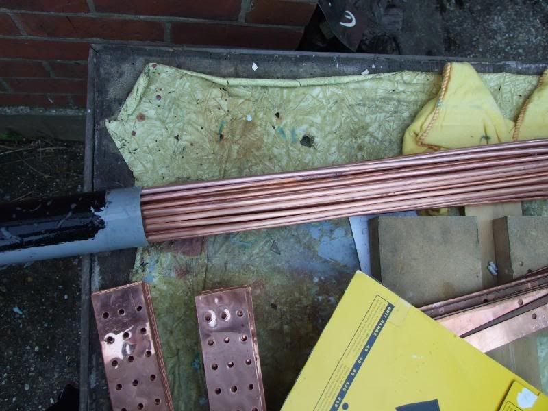
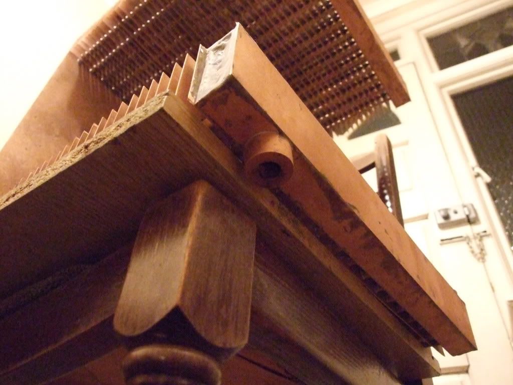
 This took a while.
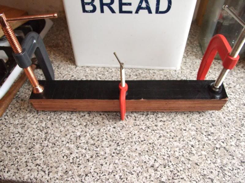

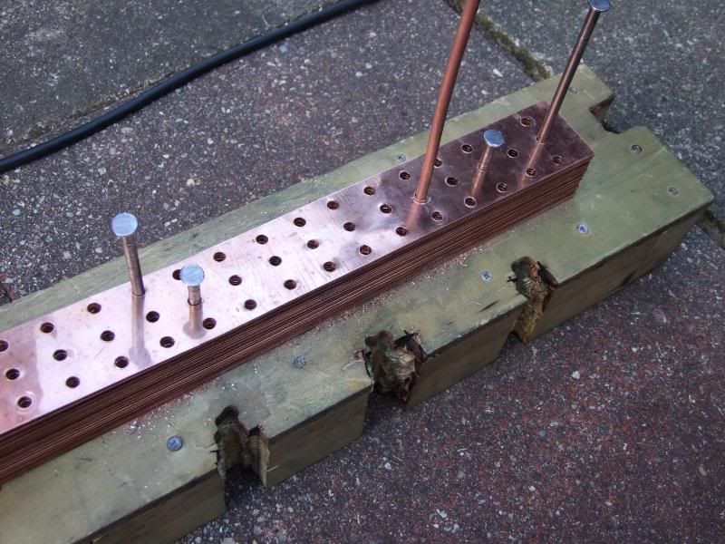
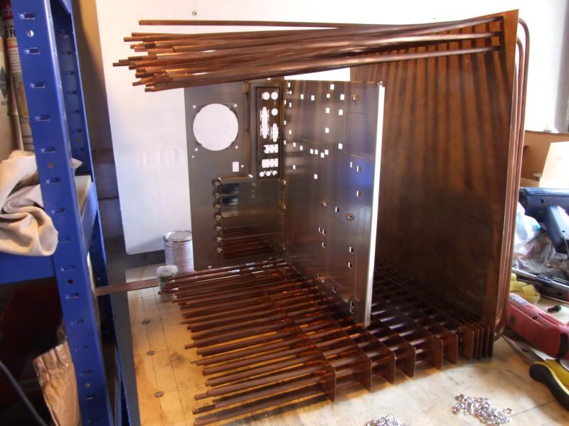
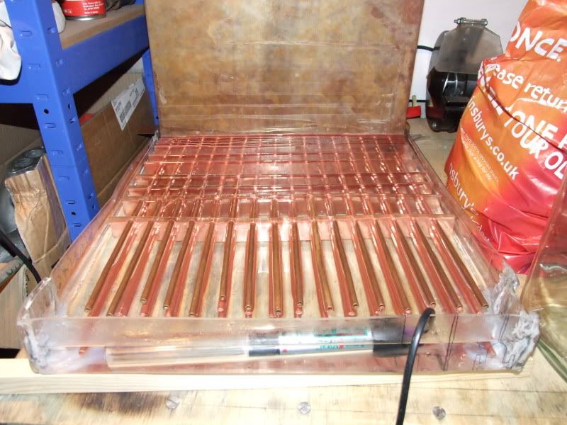
 A few of the first fins are a little bent as well, though they'll be mostly out of sight behind the motherboard tray.
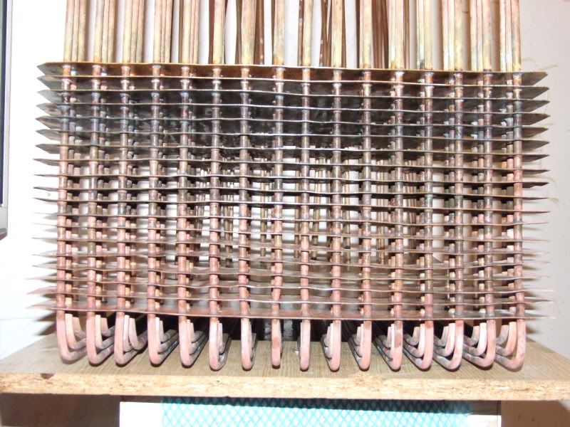
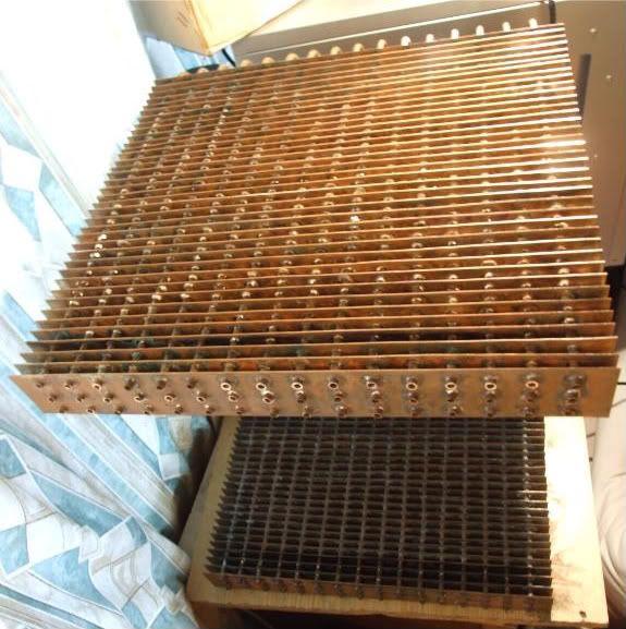
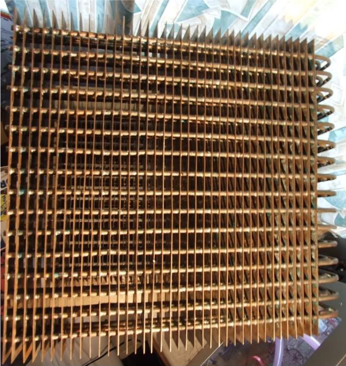
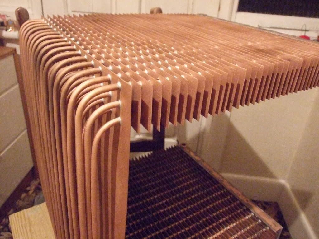
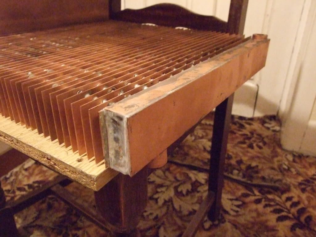
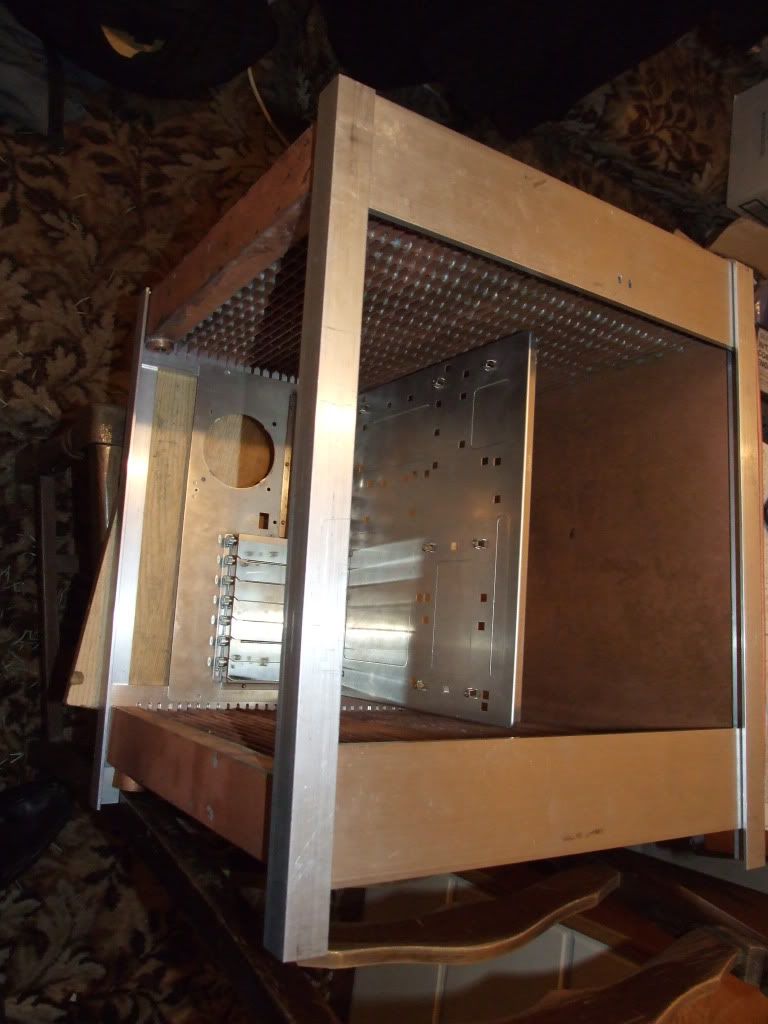
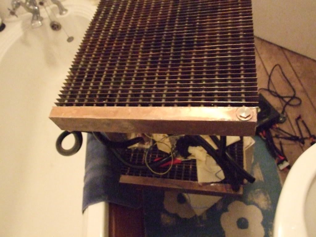
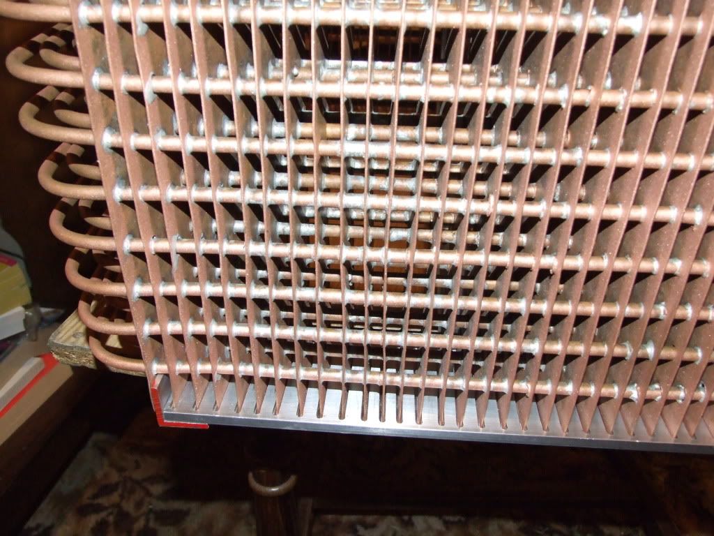
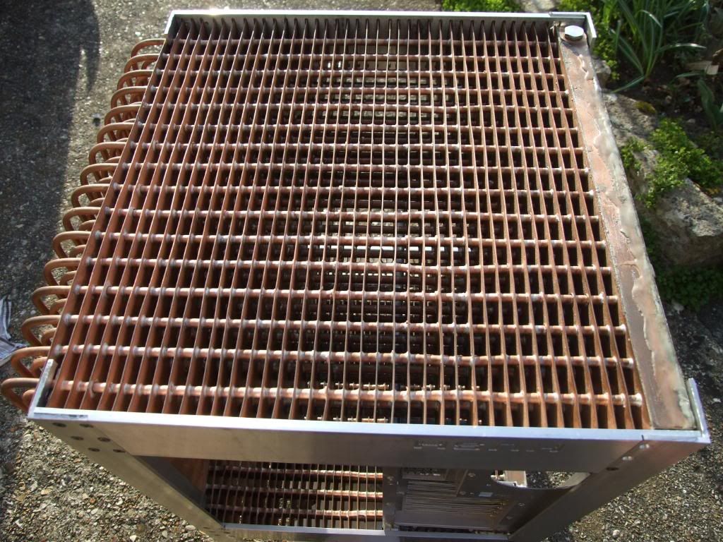
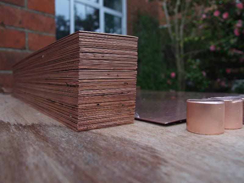
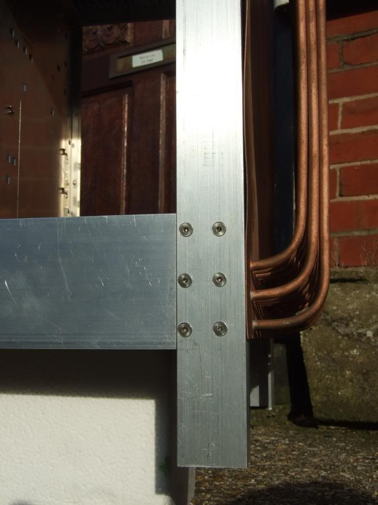
 Needs a bit of filing down to tidy up but getting there.
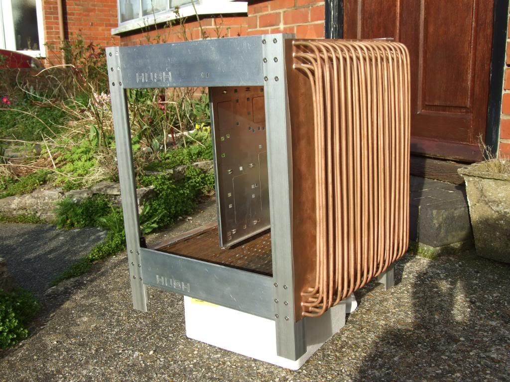


 wipe his butt with steve jobs talking about ipad..


Bookmarks