Page 1 of 2 12 LastLast
Results 1 to 25 of 46

Thread: Exoframe Mini Project

  1. #1
    Xtreme Enthusiast
    Join Date
    Dec 2004
    Location
    Chico, CA
    Posts
    749

    Exoframe Mini Project

    Exoframe Mini


    Hi all,

    Time for my new project. This is my third visit to my Exoframe concept. so technically this would be the Exoframe 3.0.

    Here is a link to the original Exoframe project.
    http://www.overclockers.com/forums/s...d.php?t=597792

    Here is a link to Exoframe 2.0.
    http://www.xtremesystems.org/forums/...51#post5110851


    And a new twist for my modding. My first official sponsorship:


    Unlike my previous two Exoframe based projects, this time I?m going compact!


    Here are my goals:

    1) Gaming PC based on a Mini-ITX platform, full sized video card, full sized power supply.

    2) Small size, appropriate for a Home Theater component.

    3) Watercooled.

    4) I already have all of my components:
    Intel I7 2700k (Swiftech Apogee HD)
    Asus P8Z77-I Deluxe
    XFX 7970 (Heatkiller full cover sink)
    Seasonic X750 power supply
    LG Blu-ray burner
    2x 4gb Corsair Vengeance RAM
    Swiftech MCP35x pump with XSPC Pump/res top
    Samsung 840 500gb SSD
    Phobya 200mm radiator

  2. #2
    Xtreme Enthusiast
    Join Date
    Dec 2004
    Location
    Chico, CA
    Posts
    749
    Here is my general plan:

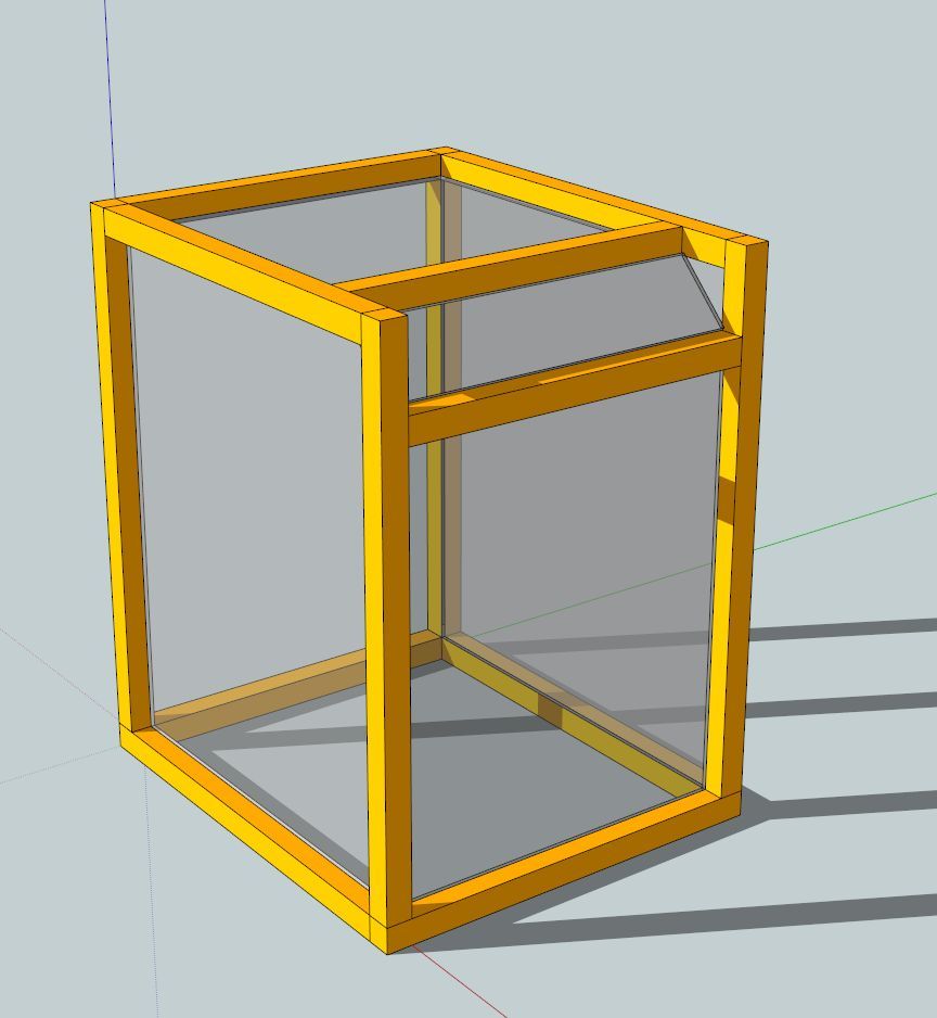
    1) Sketchup concepts, possible layouts
    2) Build a prototype and finalize dimensions and layout
    3) Build frame
    4) Build bracketry
    5) Work my sheet plastic for interior shelving
    6) Work my sheet plastic for exterior paneling
    7) Work with metal/plastic for bracketry for components
    8) Install components
    9) Fit watercooling routes, leak test
    10) Work on cabling
    11) Finalize, install windows
    12) Final photo session
    13) Locate it (home theater), settle on overclock

  3. #3
    Xtreme Enthusiast
    Join Date
    Dec 2004
    Location
    Chico, CA
    Posts
    749
    Okay, here are some Sketchup concept renderings.


    I’m going with my standard exoframe layout:


    It’s a simple box frame of ?” square tube aluminum. One corner (with the extra horizontal bars) will have a slanted panel to give it some “architectural interest”.

    I’ve included a standard football to give an idea of sizing.


    Here are some general possible layouts to fit in this rendering:


    Yes, I know my Sketchup-fu is not strong. I'm stealing free renders from everywhere and I keep seeming to loose bits of them. But I'm only using this to get some general layout concepts.

  4. #4
    Xtreme Enthusiast
    Join Date
    Dec 2004
    Location
    Chico, CA
    Posts
    749
    Okay, it was time to start constructing a prototype.

    I’m using an old kit of extruded aluminum bars. I left extra space at the joints so that I can adjust the actual sizing.

    I like sketchup, but this gives me a much more accurate sizing (especially things hard to model like fittings). The hands on nature does works better for me.

    There are a few things to keep track of, tho, for example these bars are metric based, and so will be smaller than the ?” square tube I will be using for framing.


    Started to put together the frame:


    Basic frame structure completed:


    In the place of plastic, carved up some ⅛” MDF I had around the shop, to build a base:


  5. #5
    Xtreme Enthusiast
    Join Date
    Dec 2004
    Location
    Chico, CA
    Posts
    749
    The next step was to start building up some structure. Plan is for this to be of 3/16” acrylic, but I’m going to use some ⅛” MDF I had around the shop.


    First built a support hoop for the first level.


    Finished it with a tray:


    The tray will hold the power supply:


    And then the top level would hold the motherboard.


    Then I threw in some components:


    But if you look closely, I struggled with where to put my hard drives.


    So I reworked my structure, elevating the first level to accommodate hard drives on their side:


    But as I filled in the rest of the components, I discovered that I had to make this case much taller than I had anticipated:


    This is where Sketchup designing can fool you. With clearances for the watercooling block on the video card, plus an intake fan mounted on the top panel, turns out you need a lot of space above your motherboard.

    I felt like this design was too tall, so I went back to prototyping.

  6. #6
    Xtreme Enthusiast
    Join Date
    Dec 2004
    Location
    Chico, CA
    Posts
    749
    After some more tinkering around, this was my finalized layout and size:


    I stretched the front-to-back dimension by 4 cm (notice the gap from the original floor panel).


    Bottom level holds the radiator plus hard drives on their side:


    Next level is the power supply plus 5.25 bay/optical drive:


    Top level is the motherboard:


    Here some more views, for reference.


    That was it for messing around, it was time to get building.

  7. #7
    Xtreme Enthusiast
    Join Date
    Dec 2004
    Location
    Chico, CA
    Posts
    749
    The first order of business was to generate the cut list for my square tube (?” x ?”, 1/16” thickness, ordered from onlinemetals.com)


    There are 3 types of ending I needed to cut for each length of square tube:


    Square end for a butt joint:


    Single miter to meet at this joint:


    Double miter to meet at 3-way joint::


    My weapon of choice: band saw cutter.


    Picked up my band saw pretty cheap (like $130) by stacking coupons at Harbor Freight, but this can be done (even more accurately) with a $15 miter box and elbow grease:


    Here is a video on how I do the double miter.


    It’s important to keep track of which way you want to cut the 45 degrees.


    The Cut List


    Here was the full cut list listed by what type of miter cut was needed at each end:


    Square end - square end:
    4x 270mm

    Single miter - Double miter
    2x 428mm
    2x 384mm

    Double miter - Double miter
    2x 428mm
    2x 384mm
    3x 270mm


    Couple of hours later here was my stack of ready to go pieces.


    You may notice that I’ve labeled each bar so that I can keep track of them when unassembled--here is the plan, posted here actually for my own future reference:


  8. #8
    Xtreme Enthusiast
    Join Date
    Dec 2004
    Location
    Chico, CA
    Posts
    749
    Next, I?m going to flash back.

    Part of the process for my last Exoframe based build, Exoframe 2 (link here), I put together steel 3 way corner brackets.


    The link on their fabrication is here, but I will recap.

    They started as a drawing, then CAD design (thanks to Matt Mione Solidworks), then cut from 18 gauge steel (thanks to Erik Norcal Laser).


    Bent them into shape:


    And there you have it:


    Next I had them sent off to Kwikki (raptorpit forums) for professional welding.


    And then off to Platinum Powdercoating (Chico, CA) for a matte black finish!


    Now I?ve got cut tubing and brackets--next step assembly!

  9. #9
    Xtreme Enthusiast
    Join Date
    Dec 2004
    Location
    Chico, CA
    Posts
    749
    First step to getting these bars ?n brackets together is to mark and centerpunch my marks:


    Drill them out:


    Thread them:


    And start screwing things together.


    Slowly assembling the basic frame:


  10. #10

  11. #11
    Xtreme Enthusiast
    Join Date
    Dec 2004
    Location
    Chico, CA
    Posts
    749
    Now that I had the basic external frame complete, I turned my attention to some of the supporting mounting structure. Not glorious but very necessary.


    I began fabricating what I call the “hangers”. These pieces mount to the frame and create a mounting surface for the plastic panels. The plastic panels don’t mount directly to the basic frame, but instead are inset within the frame, hence the name “Exoframe”.


    The hangers begin as ?” angle aluminum:


    Next I cut out a tab from one end:


    And then bend the tab to a 45 degree:


    And these are my completed hangers:


    The hangers then get mounted (green arrows):


    You can see how they generate a mounting surface for the inset plastic panels.


    In a similar fashion, I generate 2 short mounting tabs:


    The 45 degree bend creates a mounting surface for the slanted top panel:


    This panel needs a fair bit of support as it will hold the power buttons, and I don’t want it to feel bendy or unsecure when you push the buttons.

  12. #12
    Xtreme Enthusiast
    Join Date
    Dec 2004
    Location
    Chico, CA
    Posts
    749
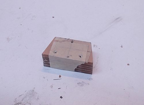
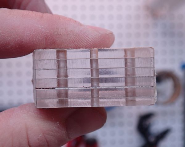
    There are some open areas not supported by my hangers, so I’m going to make some tabs to to hold the body panels.

    They are not meant to be noticed, so I’m building them from ⅛” clear acrylic.


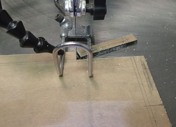
    Cut a stack of trapezoid tabs:


    Next I wanted to get the edges polished, and for this I am going to a use a brand new technique and tool.

    First I rough sanded the edges with my sanding disc thingy, getting all of the tabs exactly edged:


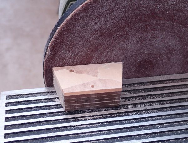
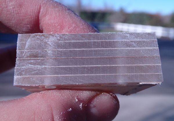
    Here was the unfinished surface:


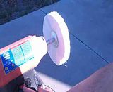
    And here I am, with my $40 Harbor Freight buffing wheel. The tool works great, but the included wheel is unbalanced (good tips from reviews on the HF website), so also ordered a buffing wheel set and buffing compound from tap plastics.

    This is the first time I’ve ever used a buffing wheel--any tips or criticisms appreciated!


    (Click to play video)


    And the finished product:


    Previously I’ve been hand sanding my edges with 220, 400, 600, 1000, 1500 then buffing with rubbing compound. Obviously this method is much faster.


    The finished eges on video:


    (Click to play video)


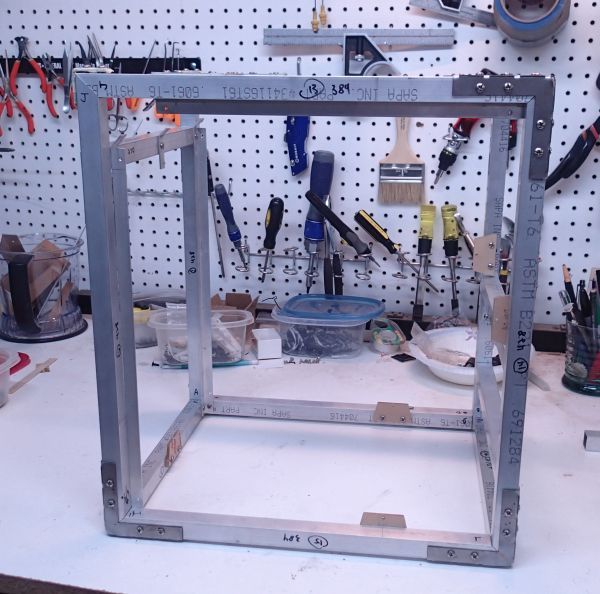
    And here are the tabs mounted up to the frame:


  13. #13
    Extreme BodyBuilder SnW's Avatar
    Join Date
    Aug 2008
    Location
    Holland,NH
    Posts
    271
    IN
    /Follow ON.

  14. #14
    Xtreme Enthusiast
    Join Date
    Dec 2004
    Location
    Chico, CA
    Posts
    749
    Side Project Alert!


    On a closely related note, recently I was able to re-acquire my project, Exoframe 2.0, from the person who commissioned it, after he had completed it (finish work, anodizing, powdercoating, and paint).


    So as little side project, I'm re-assembling it and going to post completed pics of it!


    TRP Link.

    OCforums Link.

    Extremesys Forums Link.

  15. #15
    Xtreme Enthusiast
    Join Date
    Dec 2004
    Location
    Chico, CA
    Posts
    749
    Thanks for the patience on my side project there. Back to it!


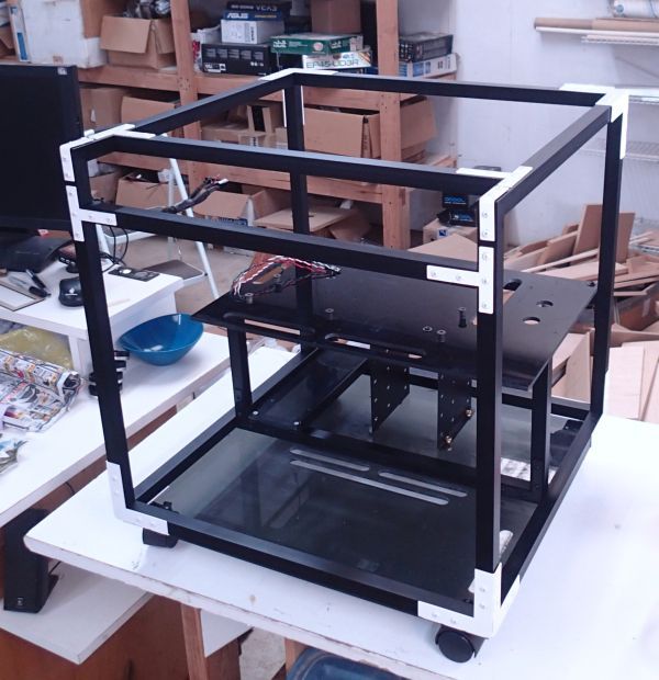
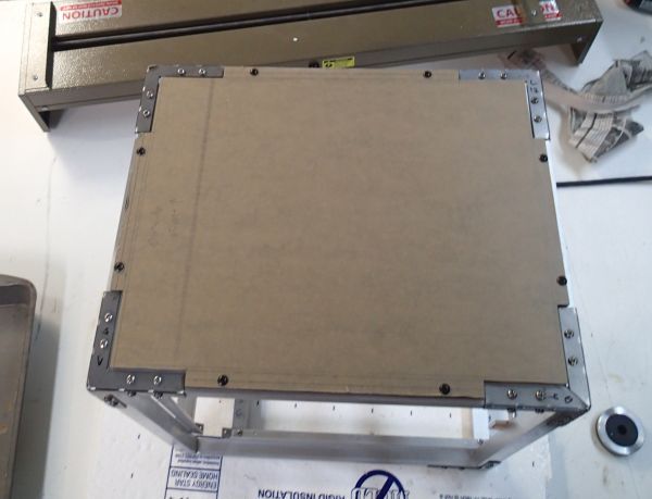
    I dove in on my plastic sheet work. The bottom panel is a very important piece as its going to be the foundation for a number of things. It was made from hefty ?” gray acrylic.

    Of course, purchased a fat stack of stock plastic from Delvies Plastics. In this project I’m going to be using ?” light gray transparent plastic, ⅛” light gray, ⅜” fluorescent orange, ⅛” fluorescent orange, ⅛” opaque black, and some very cool custom laser cut pieces (more on that later).


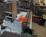
    Tee’d up on my Festool plunge cut saw.


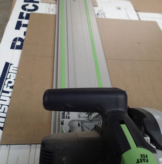
    I’ve talked about this tool before, but man I really love it. It really is as simple as put the track on the line, the drive the saw over the track. I use some rigid insulation for a sacrificial table, and some pool hosing hooked up to me shop vac, keeps things virtually dust free.

    I used to use a table saw to cut my sheet stuff. Accuracy would sometimes be off, there would often been issues with chipping at exit (even with a $150 plastic blade), and quite frankly a table saw is dangerous.


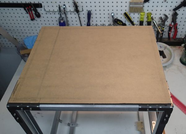
    Got the panel cut to the right size:


    Next I cut out the corners to accommodate for the corner brackets:


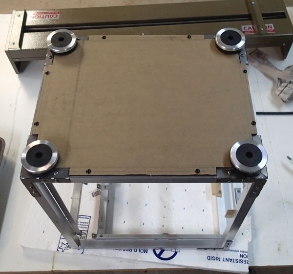
    And now it truly fits:


    Added some feet I had sitting around the shop (I think they are Silverstone).


  16. #16
    Xtreme Enthusiast
    Join Date
    Dec 2004
    Location
    Chico, CA
    Posts
    749
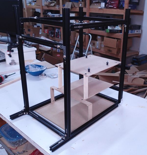
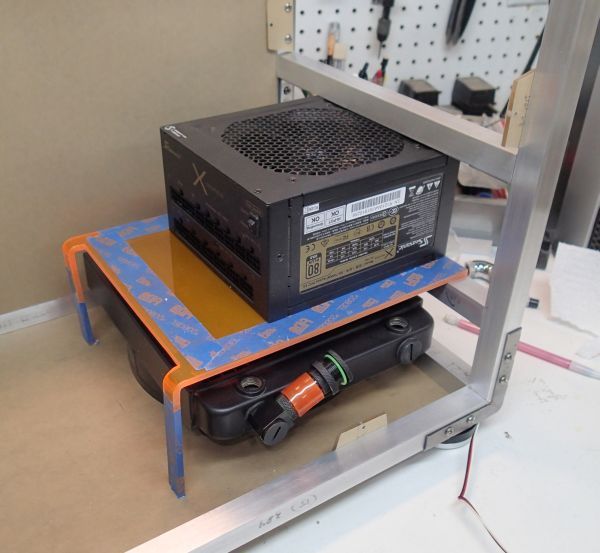
    Next step was to start building the internal structure for components. I’ve got 2 “shelves” to build: one level to hold the power supply and one level for the motherboard. In my mockup here I just cut up some shelves of plywood:


    Plan: bend some structural plastic.

    Project thus far is stuff I have done before (cutting, drilling, tapping metal), and I have bent sheet plastic before, but never to hold significant weight and requiring this degree of precision.


    First I started with sheet 3/16” thick fluorescent orange acrylic (Thanks to Delviesplastics).

    Why 3/16” thickness? ⅛” is too thin to hold significant weight, and ?” is getting too thick to easily bend.

    Why fluroescent orange? Maybe we’re going UV reactive for the internals of this build?


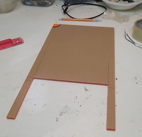
    It is currently slightly oversized in lengths--after bending (which will take up a small percentage of length), I can trim it down to exact size.


    Next I set up a jig to accurately bend my plastic.


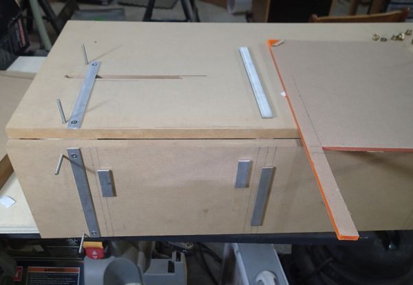
    It’s got the 90 degree bend, plus its got a lot of guides to keep everything square.


    Placed the plastic panel on the strip heater:


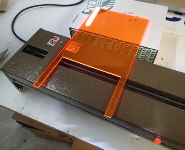
    When it was soft and bendy, maybe 5 minutes, transferred it to my jig:


    Here’s a video of the actual process:


    (Click to Play)


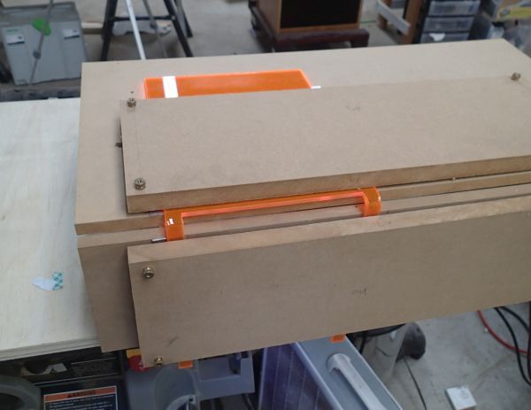
    Once cooled, remove from the jig and voila:


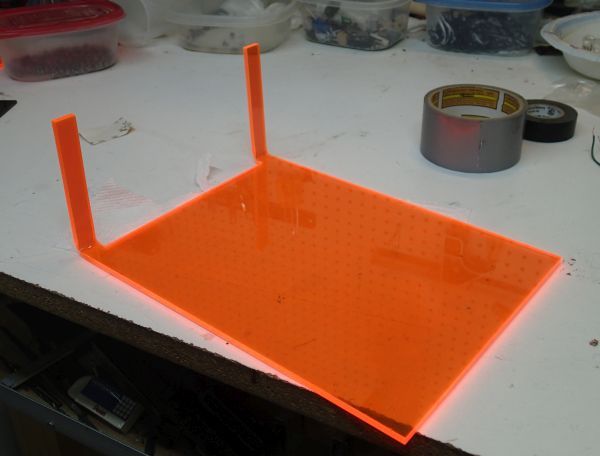
    Dropped the piece in over the radiator unit and started trimming it to fit:


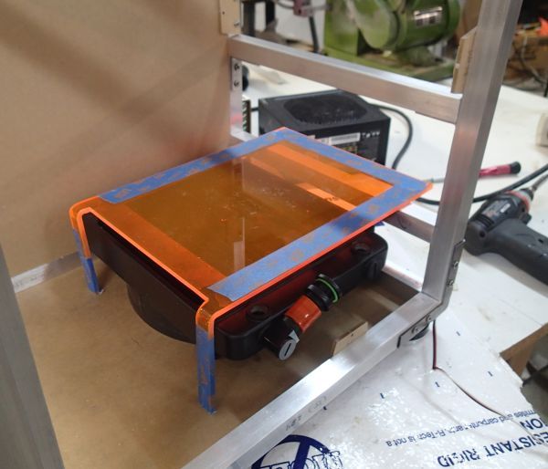
    And here it is, sized and doing its job:


  17. #17
    Xtreme Enthusiast
    Join Date
    Dec 2004
    Location
    Chico, CA
    Posts
    749
    Not done yet! Gots to make it purdy.


    Drilled out a bunch of holes:


    Added clips to hold the powersupply:


    And now it was done:


  18. #18
    Xtreme Enthusiast
    Join Date
    Dec 2004
    Location
    Chico, CA
    Posts
    749
    Time to get to work on the upper shelf unit, which holds the motherboard.

    This was how I laid it out during the planning phase:


    But a flash of inspiration came to me on how to support the 2 shelves, as you will shortly see.


    First I laid out the panel flat, with all my cuts planned:


    This was a lot of fun because I used just about every technique I?ve got to carve out this panel.


    Jigsaw for a square cut out:


    Unibit for large holes:


    Jigsaw to convert the center 2 holes into a slot, for cable pass thru.


    And even the plunge cut tracksaw for long straight cuts:


    And there it was!


  19. #19
    Xtreme Enthusiast
    Join Date
    Dec 2004
    Location
    Chico, CA
    Posts
    749
    Just like the previous shelf, this one gets its legs bent!


    And there you go, my 2 shelf units:


    Let me show you how they go together!


    Approximate layout, prepping for trimming:


    And mounted up!


    This was what came to me like a dream--the two support pillars actually of continuous bent plastic, kind of flowing together. Technically I wasn’t so sure I could get everything so accurate to make it happen, but it worked no problem.


    .

  20. #20
    Xtreme Enthusiast
    Join Date
    Dec 2004
    Location
    Chico, CA
    Posts
    749
    You may have noticed on some of the pics above that I’ve also installed my hard drive mounting system.

    Actually what happened was that in between building the two bent shelves, I found out I had under-ordered my size of 3/16” thick orange plastic sheet. So I had to order up some more. Thanks to Delvie’s Plastics, just a 2 day turn around, but I did put together my hard drive system in the interim (just made more sense to post out of chronologic order, tho).


    I’ve used this type of hard drive mounting system multiple times in the past--simple but effective.


    I start with 3 identical brackets of ⅛” plastic sheet:


    Add mounting holes and screws/washers in order to mount drives:


    Cross bracket will hold the drive brackets down:


    Time to move it in to the actual case. First, I mounted the cross bar, raised with standoffs and rubber nut guides:


    Get the brackets mounted:


    And here it is installed:


    And situated with the mounting shelves:


    Here’s a little demo video on how to mount hard drives:


    (click to play)

  21. #21
    Xtreme Enthusiast
    Join Date
    Dec 2004
    Location
    Chico, CA
    Posts
    749
    Now that I had all my major structural components ready, I wanted to test fit my major pieces to get a general idea of layout and fit.


    Empty System:


    Add the mobo:


    PSU:


    Graphics card and radiator:


    Things stack up nice thus far!

  22. #22
    Xtreme Enthusiast
    Join Date
    Dec 2004
    Location
    Chico, CA
    Posts
    749
    Time to fabricate a pump/res mount.


    Cut this form from the orange plastic:


    Mounts to my MCP35x/EK cylinder pump/res:


    Here’s where I set it, front and center:


    And mounted up:


    I know it looks a little saggy. No worries, in the end it will be supported by a fillport above and the blu ray burner below.


    .

  23. #23
    Xtreme Enthusiast
    Join Date
    Dec 2004
    Location
    Chico, CA
    Posts
    749
    My next step was to construct my support and brackets for the 5.25 optical drive.

    However, before I build all that I needed to locate my 5.25 drive.

    After a lot of measurements, I settled on the vertical height, and since the drive would be anchored to the front panel, first I constructed the front panel.


    The panel is made from transparent gray plastic.

    The bezel is a made from ⅛” opaque black plastic, and laser cut by Delvie’s Plastics. Contacted Delvies prior to this build, knowing that I would want 5.25 sized bezels for this and future builds. Making 100% accurate shapes like this (cutting out the inside square) is difficult by hand, and super easy by laser.


    Made my hole in the plastic--this hole doesn’t need to be super accurate as the bezel will overlay it.


    Mounted the panel up, and here is where the Blu-Ray burner will be.


  24. #24
    Xtreme Enthusiast
    Join Date
    Dec 2004
    Location
    Chico, CA
    Posts
    749
    Plan for the mounting brackets for the blu-ray drive would be a pair of supports that mount to the sides of the drive and span from the vertical orange posts to the front panel bezel.


    Started with some straight pieces of plastic:


    And bent the ends:


    This was the their basic shape:


    Located my mounting holes to the drive:


    Ends get threaded holes:


    Located my attachment height to the main posts:


    And mounted up the brackets:


  25. #25
    Xtreme Enthusiast
    Join Date
    Dec 2004
    Location
    Chico, CA
    Posts
    749
    So, once again, time to mount up my hardware and check my clearances.


    Radiator goes here:


    PSU and mobo into their shelves:


    Blu-ray drive mounted up:


    And mount the reservoir:


Page 1 of 2 12 LastLast

Bookmarks

Bookmarks

Posting Permissions

  • You may not post new threads
  • You may not post replies
  • You may not post attachments
  • You may not edit your posts
  •