Page 1 of 3 123 LastLast
Results 1 to 25 of 68

Thread: Project: ProtoHype - 23 may

  1. #1
    Registered User
    Join Date
    May 2010
    Location
    Sweden
    Posts
    39

    Project: ProtoHype - 7 dec, case top

    PROTOHYPE

    Hey
    I'm all new to this forum. Been lurking around for some time though but it's not until now that I realize the real potential of this place. At first I couldn't find a thing.. but then I found this section with the worklogs. I thought I would give it a try to post my ongoing project here since Im looking forward to hear your opinions aswell as to share and recive ideas and tips. This is my first computer related project, and therefore my introduction to watercooling. Even though its my first watercooling setup, im pretty familiar with the basics of watercooling since I've been reading a lot about the subject. But there is nothing as valuable as feedback from the ones who is experienced.

    Who am I?? I'm currently in the last steps of completing my design engineering studies att university. Will be finished in a couple of weeks and after that I will be devoting my time to job searching and this project. Ever since I was a little kid I have loved drawing and building things and I still do today. The urge of building things is why I'm doing this project.

    This project has actually been going on for quite some time, but I was late to post the log on this forum and therefore, I got some catching up to do. There will be quite a lot of updates in the beginning until I get to the stage I am at the moment. At the beginning of this project, I hadn't access to any real workshop and therefore I decided to invest in my own tools lika a mill and lathe as you will see in the pictures below. Ironicaly a couple of months later I got acess to my schools workshop with a lot bigger tools.

    Why ProtoHype? If I'm gonna try to relate it, it's probably because it is supposed to look more like a machine prototype of some sort and I guess the hype could be related to all the totally unnecessary stuff I will put in it to make it geeky enough. It was first intended to be some kind of steampunk theme but it evolved into a more modern kind of steampunk machinery look.


    Specifications

    Case
    • 2 seperate watercooling loops, one out of ALU and one copper
    • Custom waterblocks for cpu, nort/south bridge, RAM's, HDD and maybe GPU
    • 3x120mm Black Ice Extreme Radiator
    • External watertanks
    • Front acts as a radiator
    • A lot of aluminium


    Hardware
    So far I have desided to wait with the hardware until most of the case is finished. The hardware I currently got is not top notch, and therefore any potential new hardware is put on hold because any large economical funds are absent at the moment.


    And now to the pics.

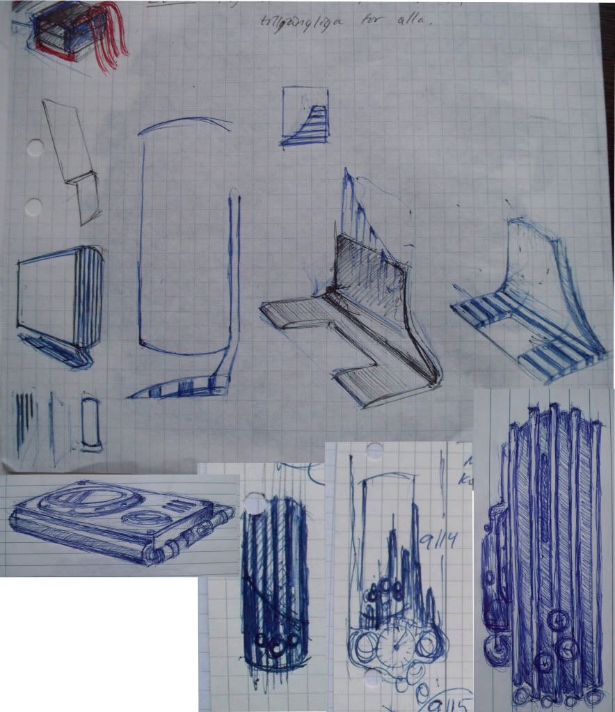
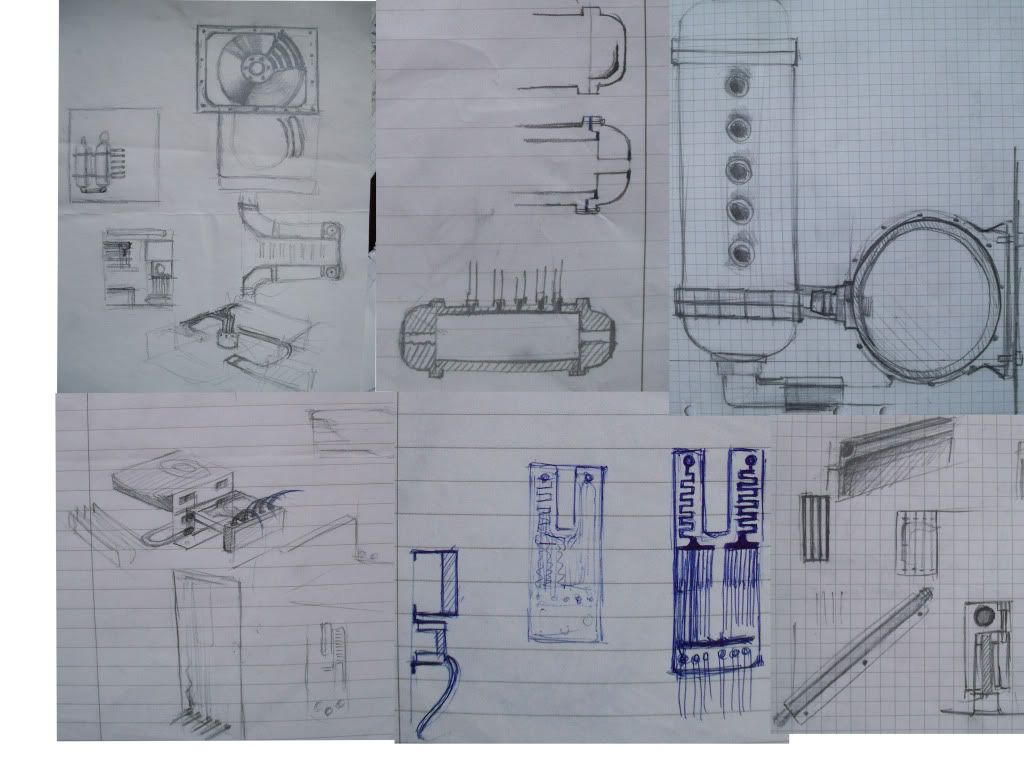
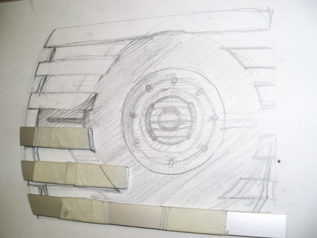
    Here is some of the doodle sketches that have been made. No top of the line sketches, but at least it shows how some of the ideas are developing. As you can see from the paper of choice this is what happens when I'm bored in class.


    (CLICK TO ZOOM)


    (CLICK TO ZOOM)

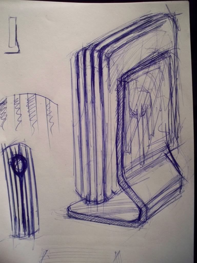
    Here is one of the ideas for the foot, not the definit one but a hint of what's in my mind.

    (CLICK TO ZOOM)

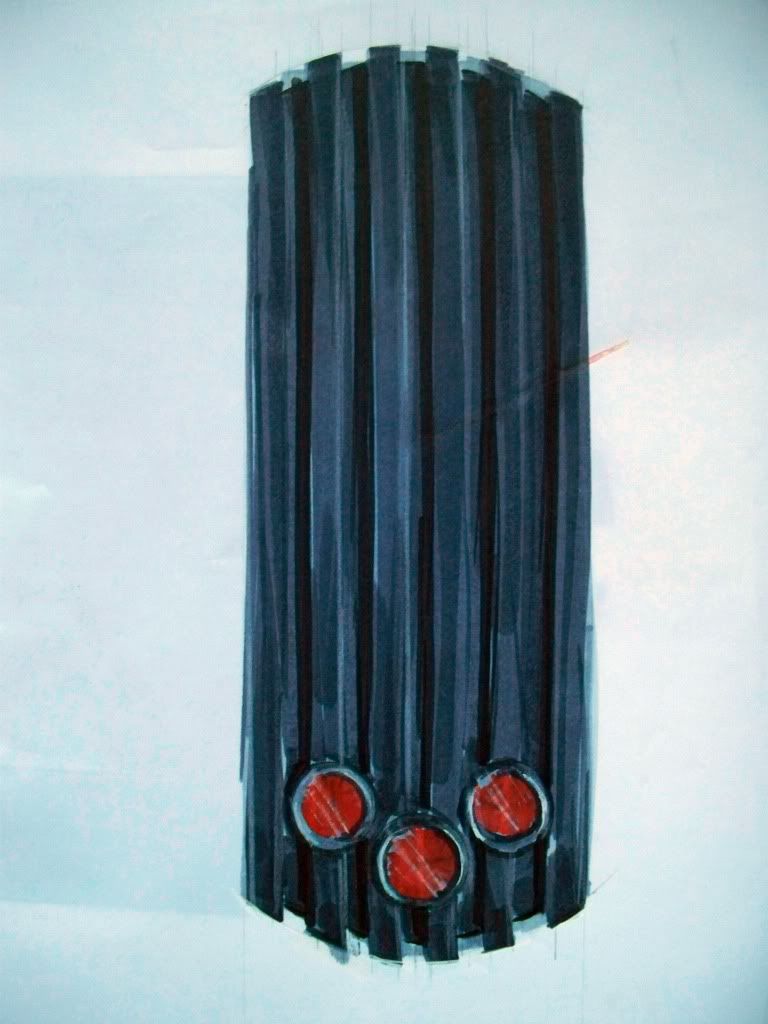
    Here is a simple marker sketch to practice some drawing.

    (CLICK TO ZOOM)


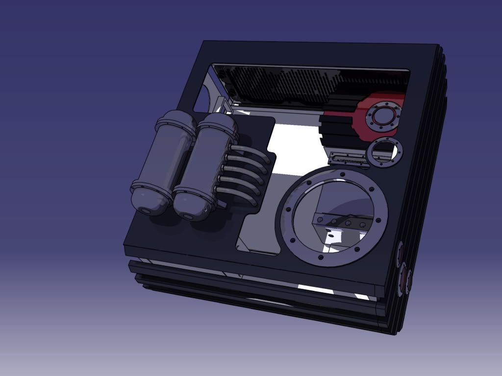
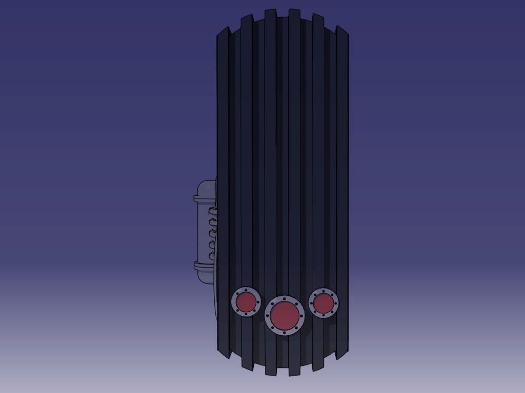
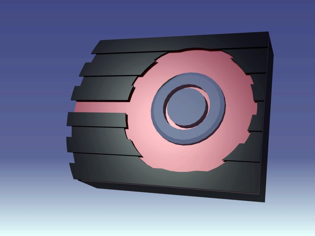
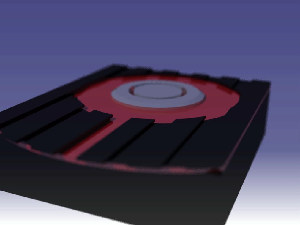
    Here is some basic 3D renders to get a better understanding of what I'm trying to do. I focused the modeling to the exterior of the main body. I didn't bother to putt much effort into all the details as I think there need to be some moment of surprise to keep a worklog interesting. And some parts are left out because I simply haven't decided what to do yet. As for the case feet.


    (CLICK TO ZOOM)


    (CLICK TO ZOOM)


    (CLICK TO ZOOM)


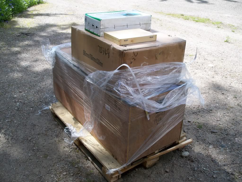
    As I mentioned previously I ordered a couple of new tools too be able to fabricate all the bits and pieces I wanted. And if I can't get to the schools workshop, I'll have to build my own .. even if I'll have to spend all my savings.
    Here's one of the packages.


    (CLICK TO ZOOM)

    Tada... a brand new 9x30 lathe

    (CLICK TO ZOOM)

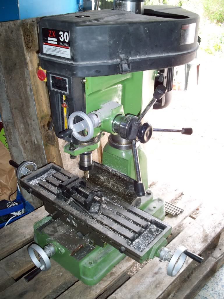
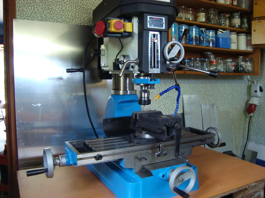
    Next tool arived like this. Not as brand new. Kind of messy and badly treated..

    (CLICK TO ZOOM)

    ...So while I waited for the electrician, i took some time disassembling, cleaning and repainting it.


    (CLICK TO ZOOM)

    Finished.. much nicer to work with this

    (CLICK TO ZOOM)

    That mill weighs 350kg and I had to get it up there on my own. Never thought I would make it but with a lot of elbow grease, some rollers and a bandy stick it's sits where it 's supposed to.

    (CLICK TO ZOOM)

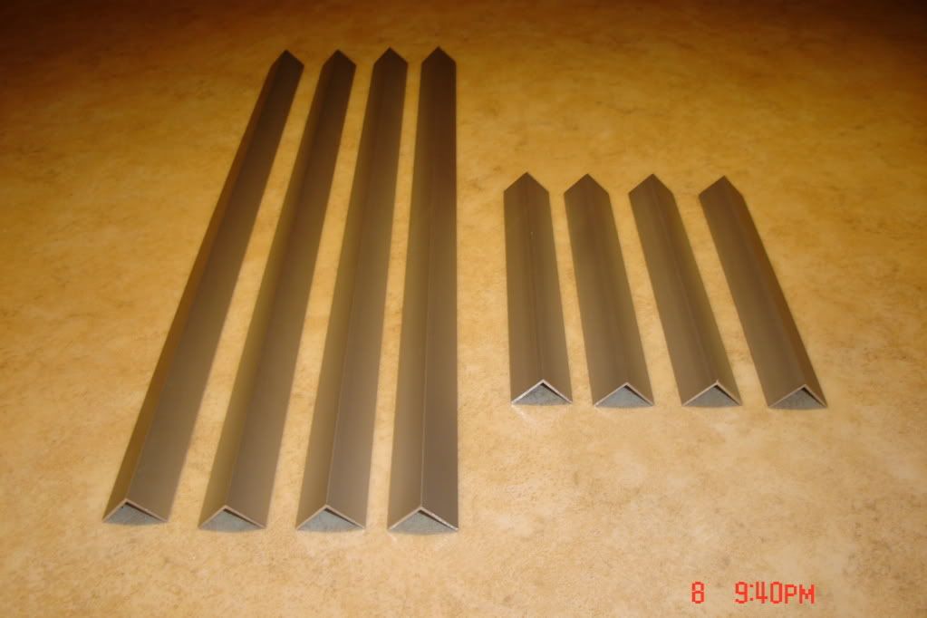
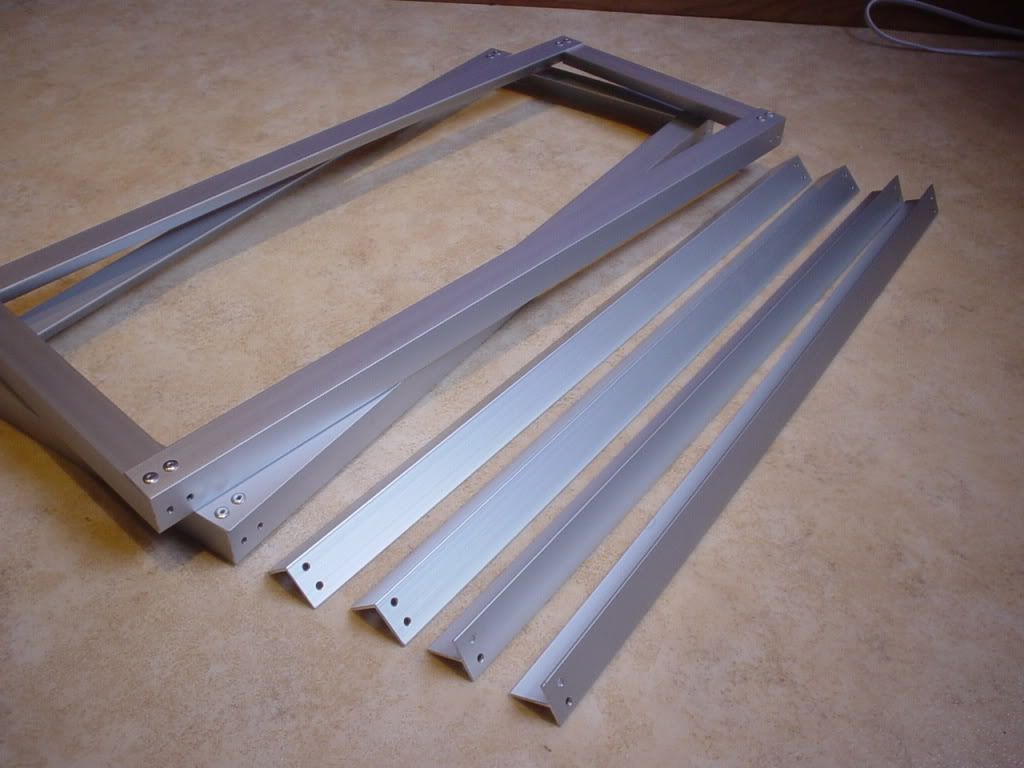
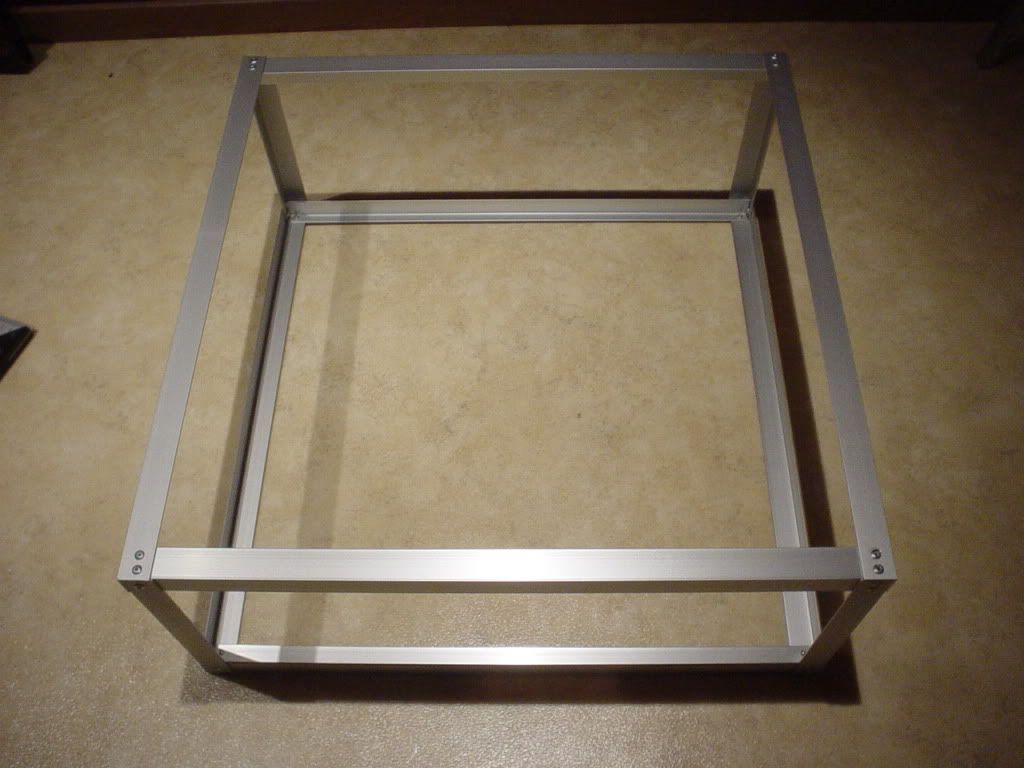
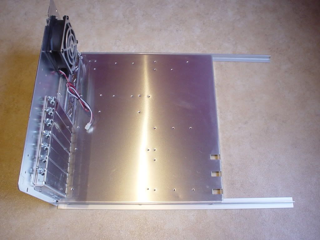
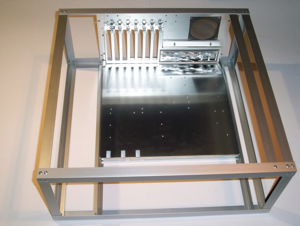
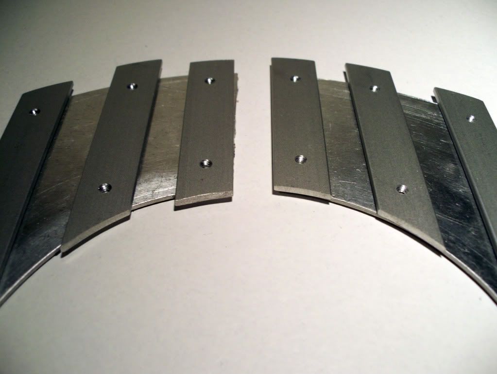
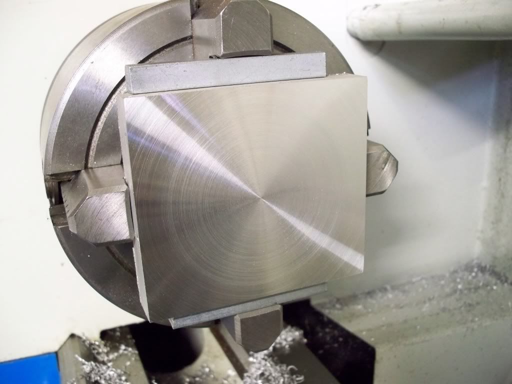
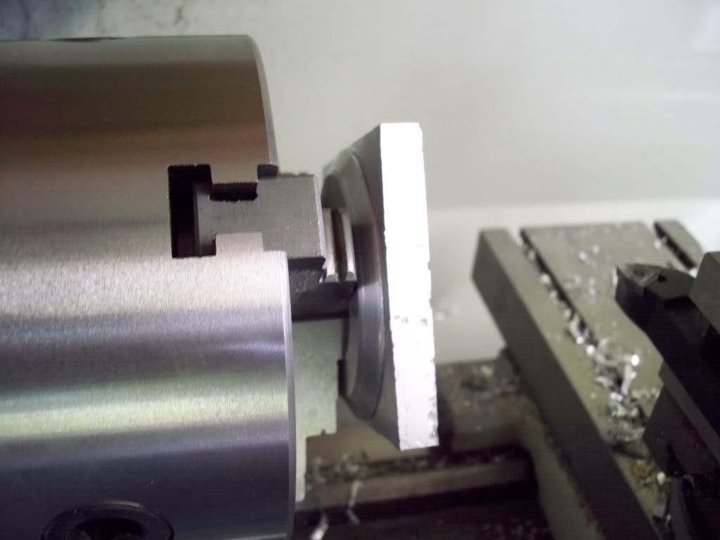
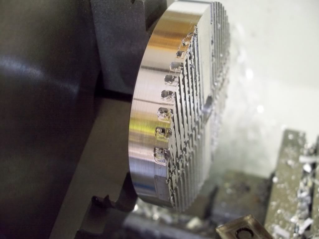
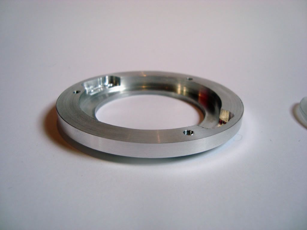
    Okay now for the Construction of the case itself. Guess the pictures speak for them self.

    (CLICK TO ZOOM)


    (CLICK TO ZOOM)


    (CLICK TO ZOOM)


    (CLICK TO ZOOM)


    (CLICK TO ZOOM)

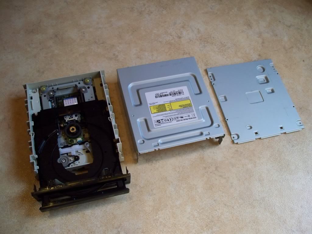
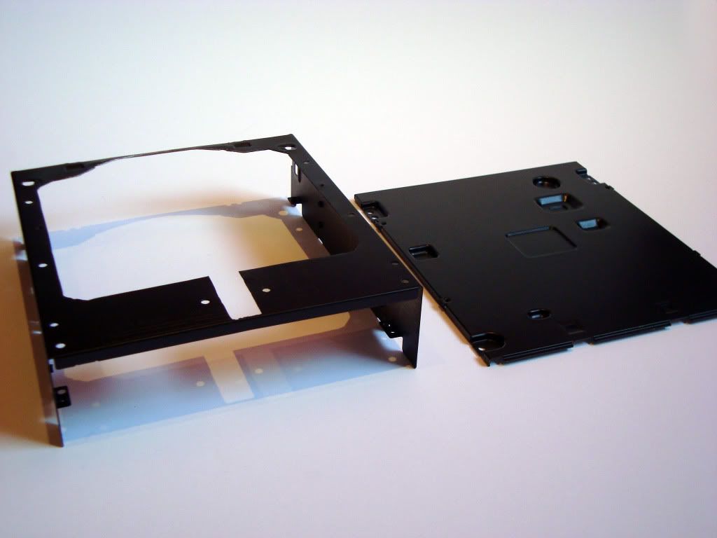
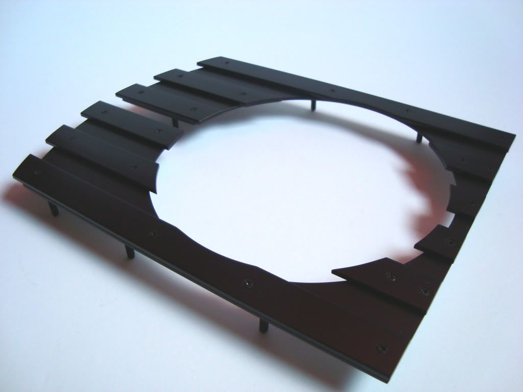
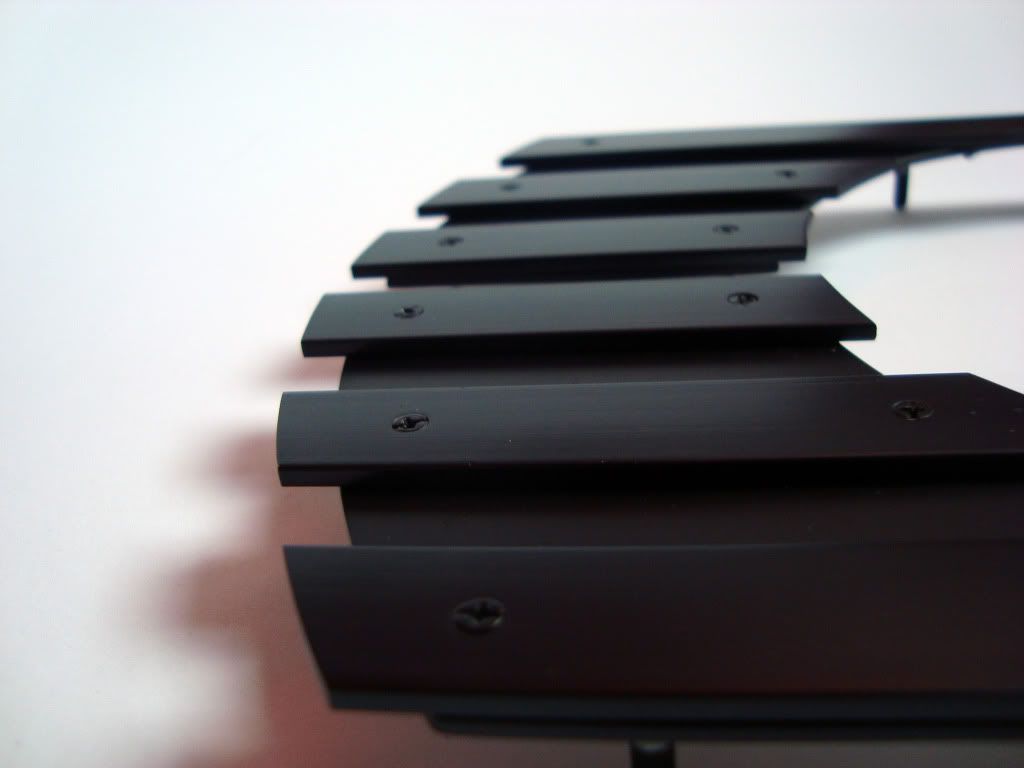
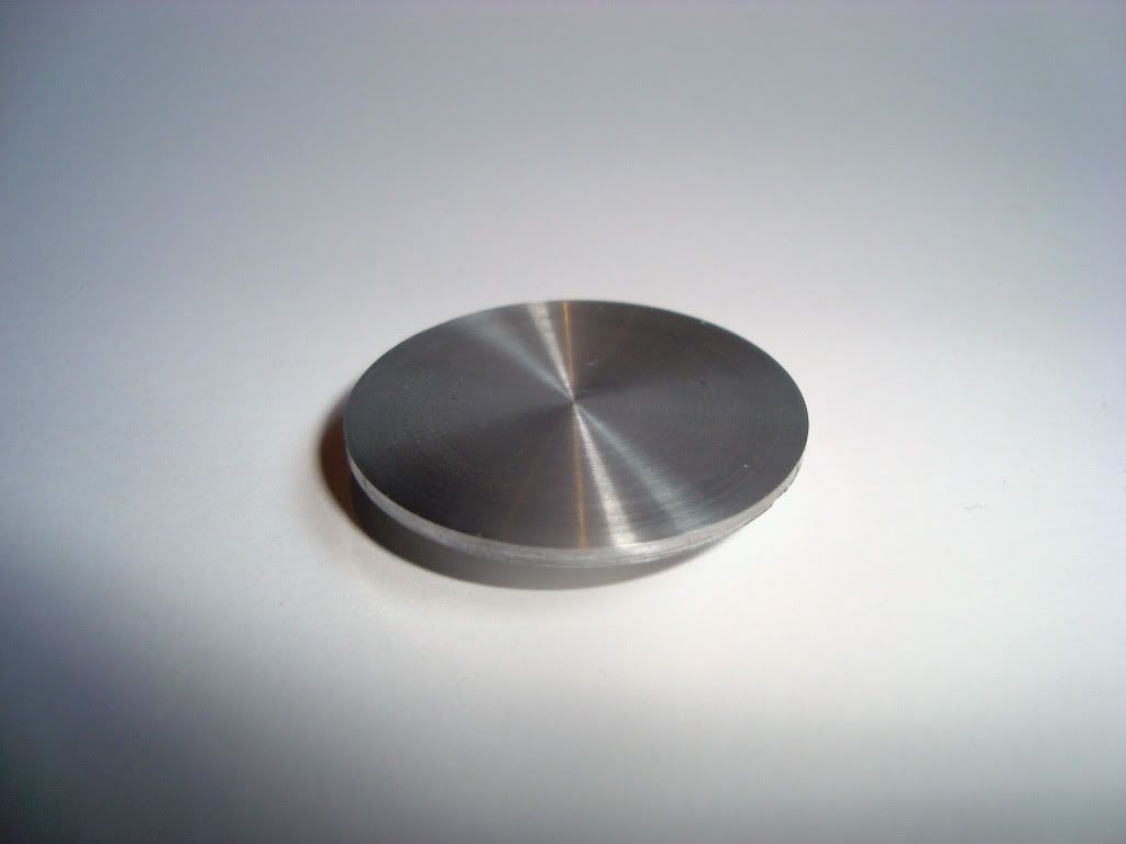
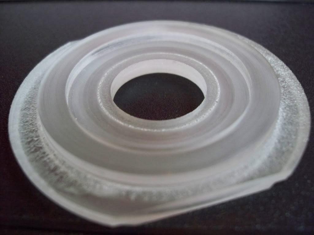
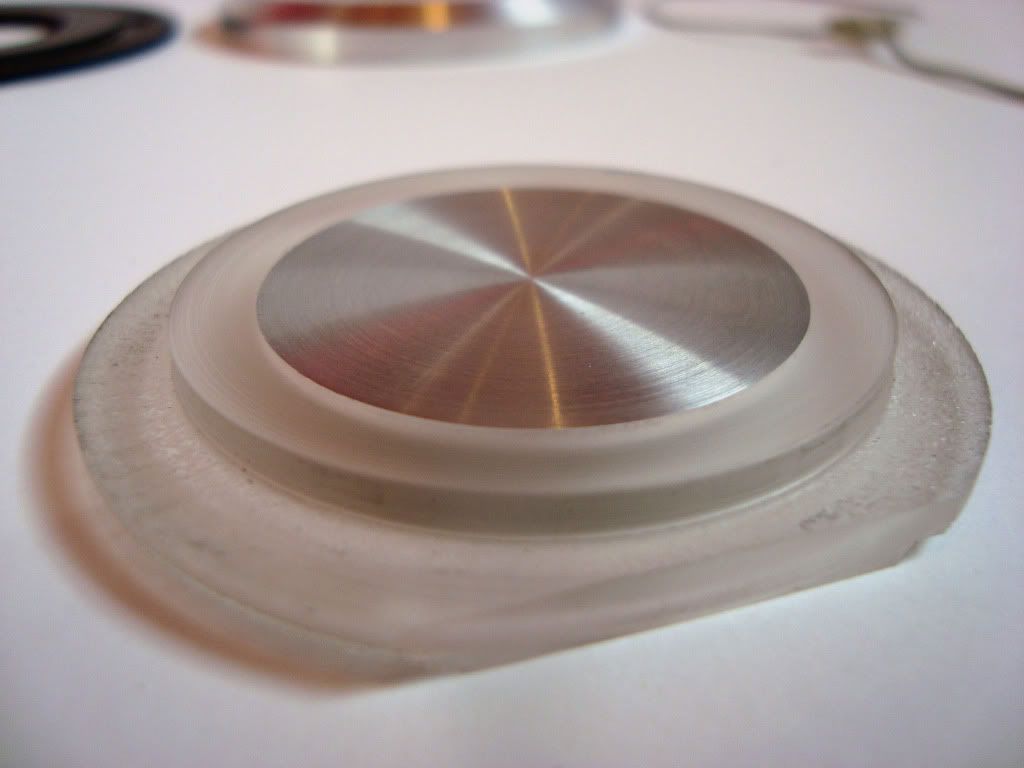
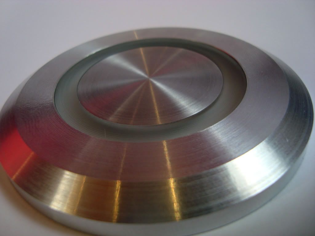
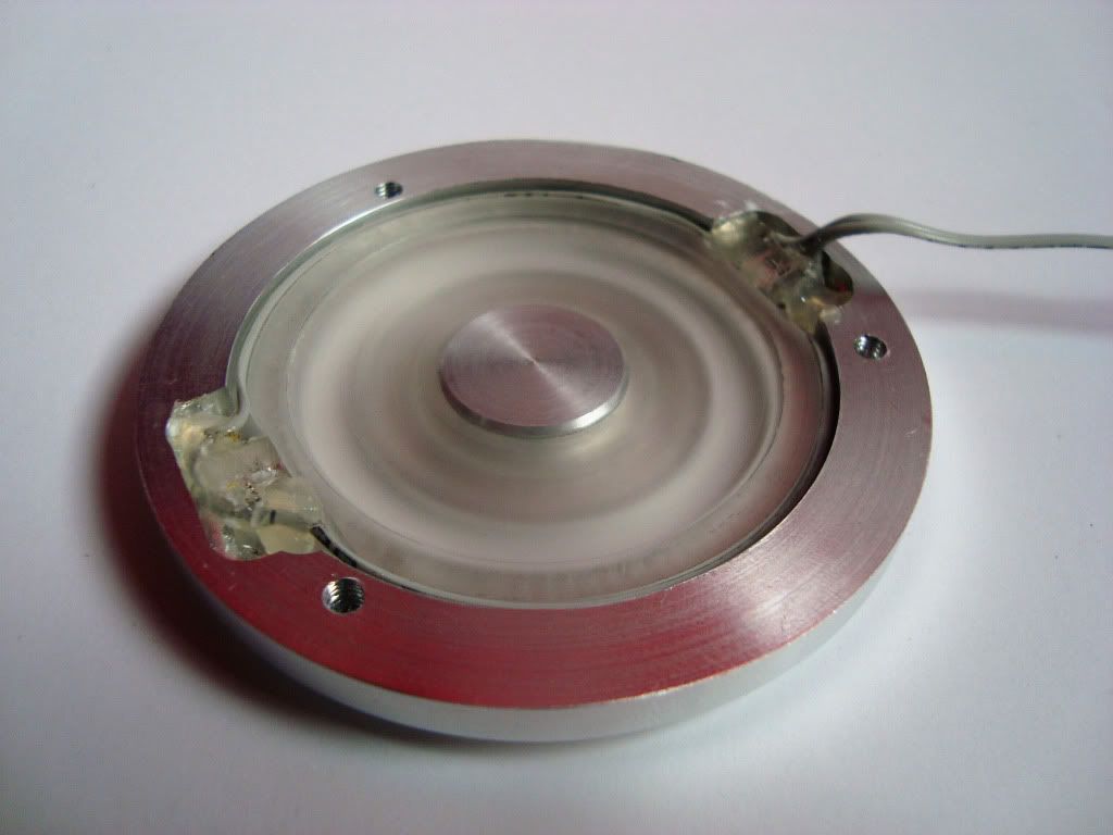
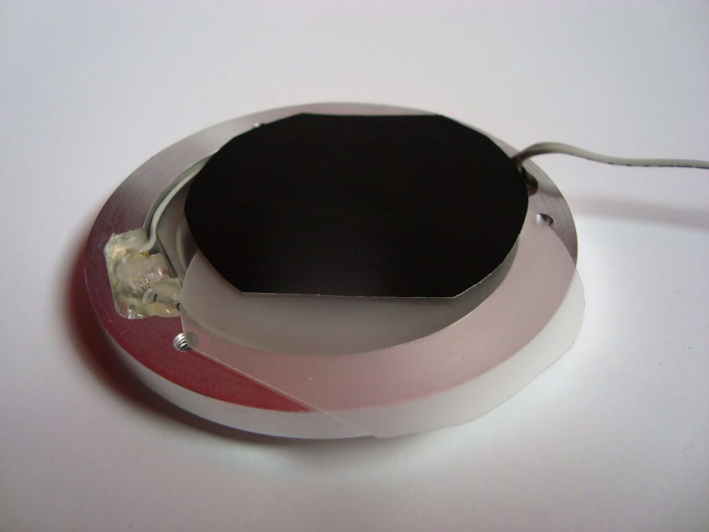
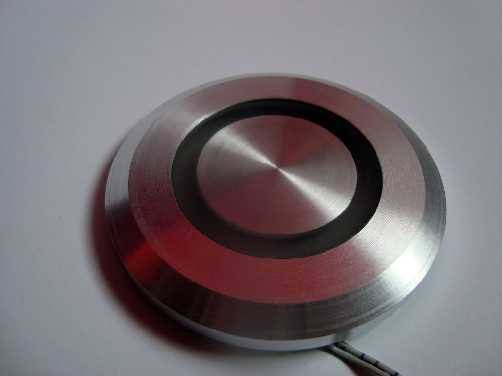
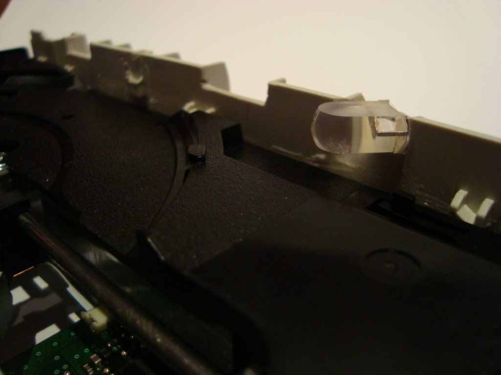
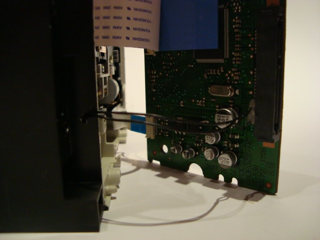
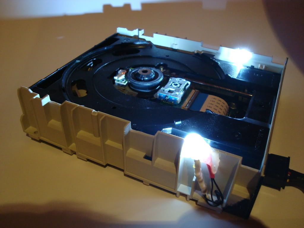
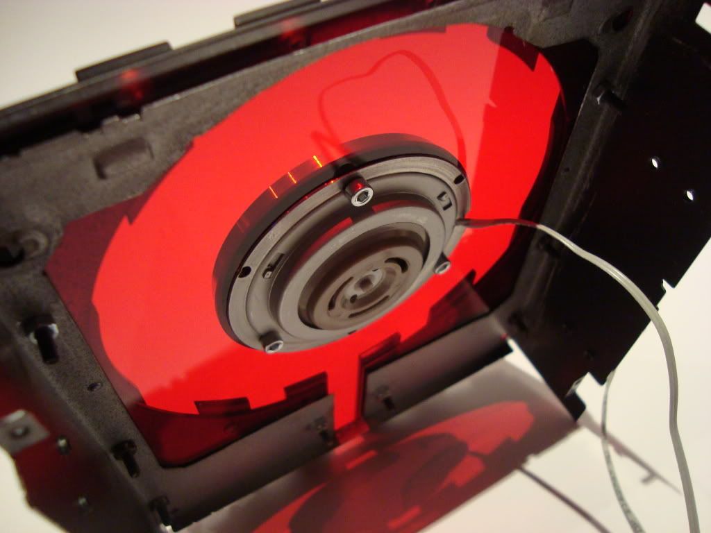
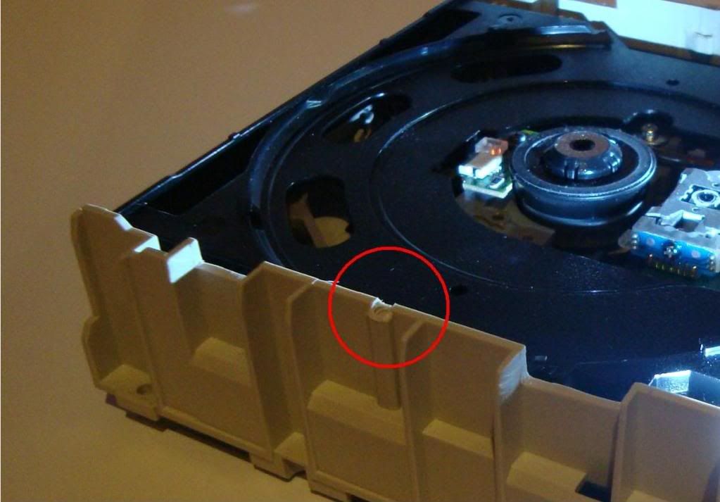
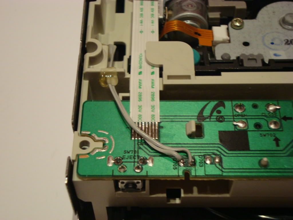
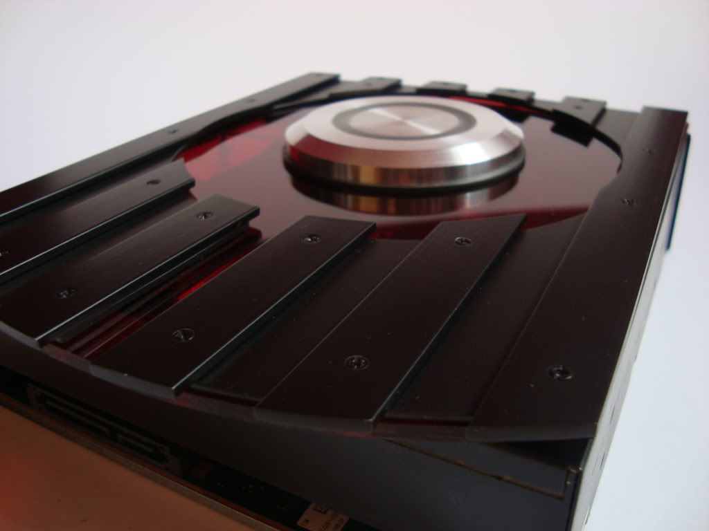
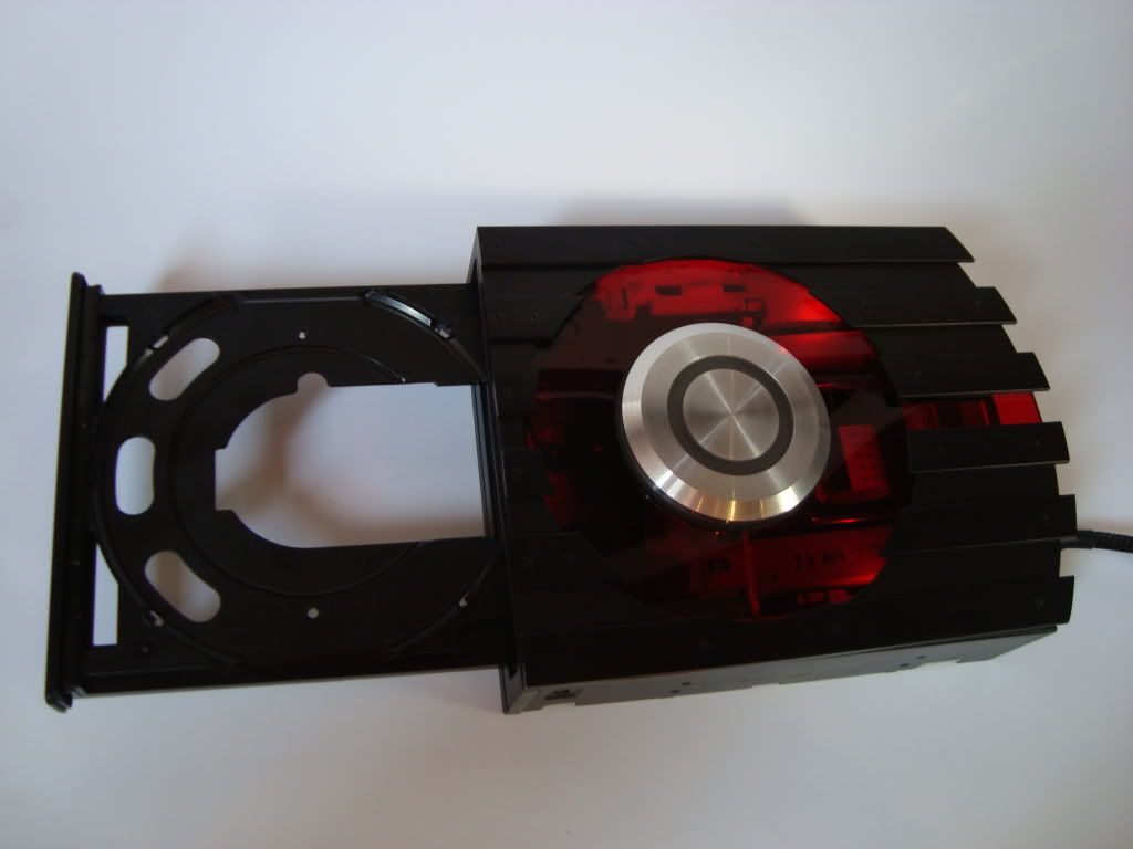
    This is the window mod of the DVD-drive. This was created before I had my mill and lathe and it took a lot of blood, sweat and tears. Since I'm such a freak when it comes to the finish of the things I do, I often spend way to much time trying to achieve perfection. I often end up redoing some parts over and over again until I'm satisfied. I'm not kidding when I say I have at least spent 100 hours on this DVD drive.

    As you probably notice I have removed the center magnetic ring that is supposed to support the disk from above. This will be added later onto the plexi window because I want the window as big as possible. This proved to be one of the mor time consuming tasks.

    But anyway here are the pics


    (CLICK TO ZOOM)


    (CLICK TO ZOOM)


    (CLICK TO ZOOM)


    (CLICK TO ZOOM)


    (CLICK TO ZOOM)


    (CLICK TO ZOOM)


    (CLICK TO ZOOM)


    (CLICK TO ZOOM)

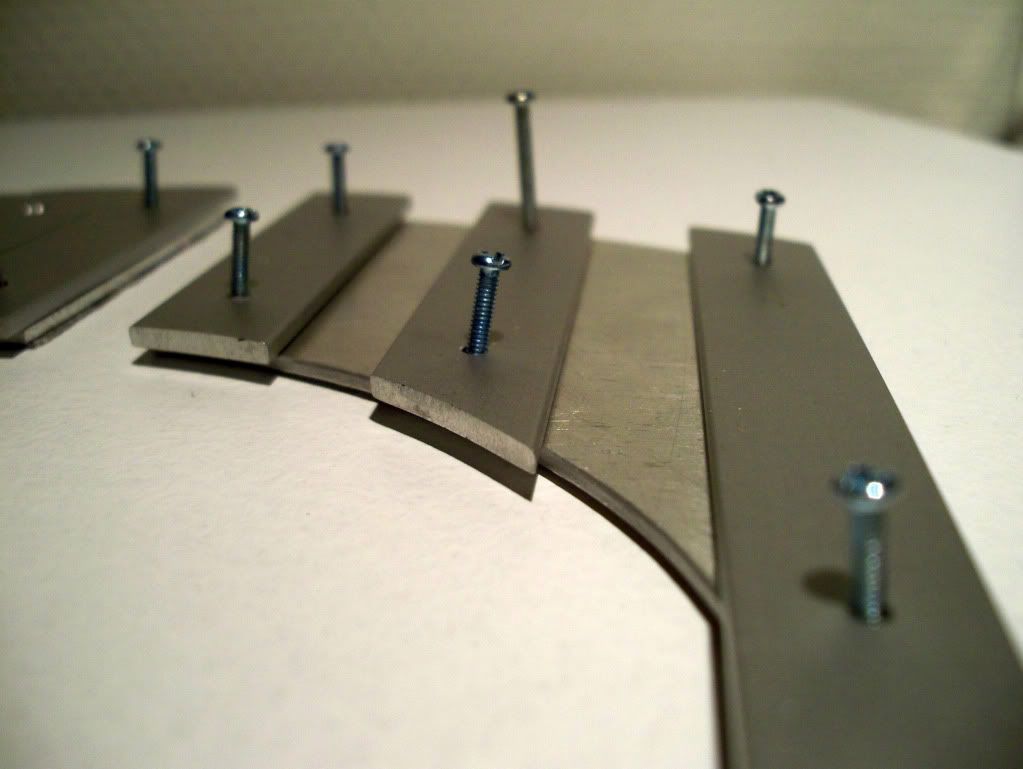
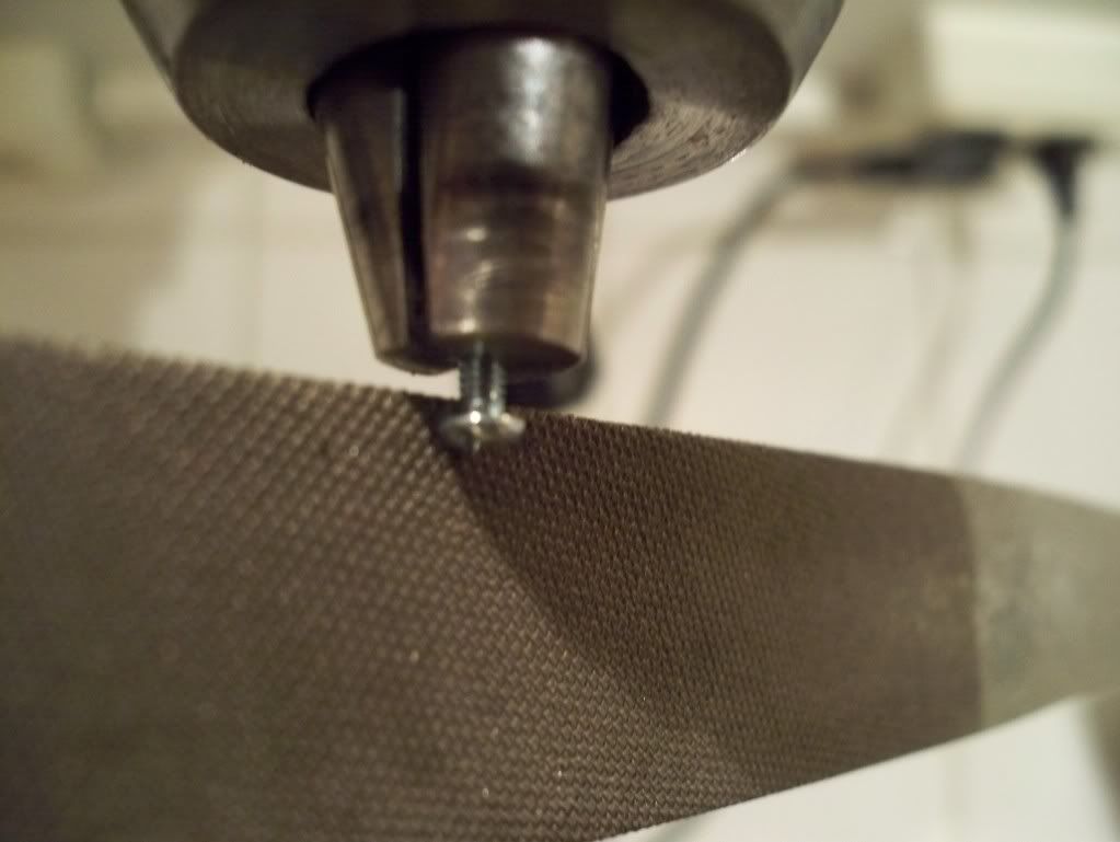
    Each of the screws had to go through a makeover in the drillpress. Using a file, I trimmed them down to make them flush with the rest of the drive case. They were also shortened to the right size.

    (CLICK TO ZOOM)

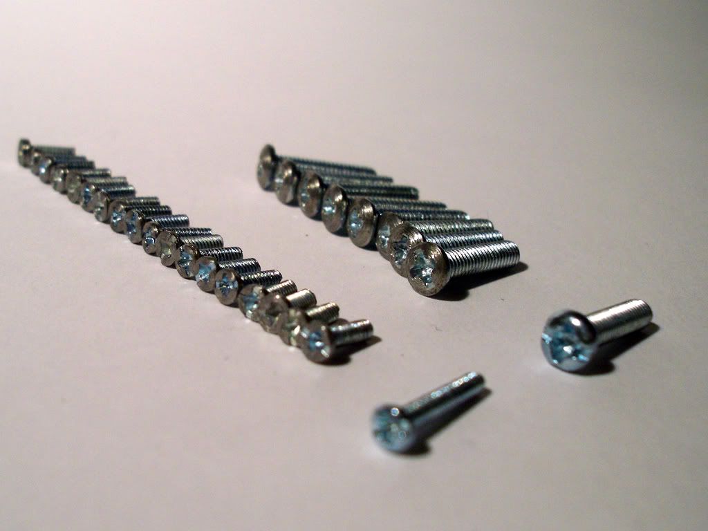
    Here they are all done. The original screws are the ones in the front. The surface of the modded screws doesn't look that rough in reality. It is probably because this is such a macro shot and the screws are M2 and M3.

    (CLICK TO ZOOM)

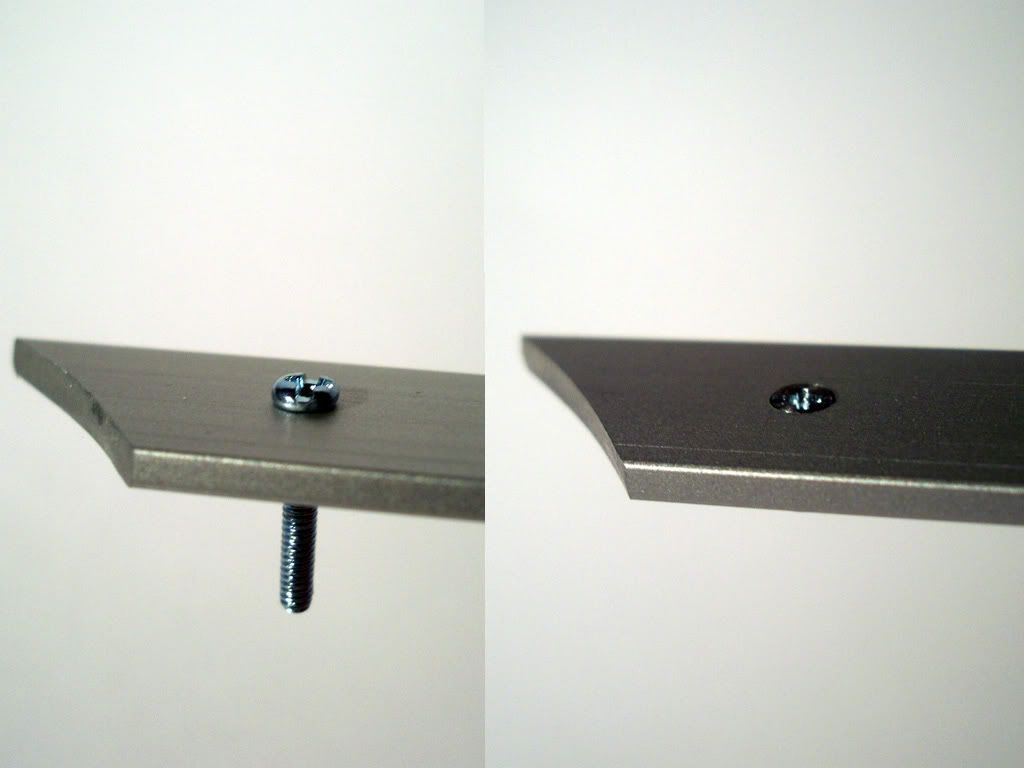
    Before and After shot of the trimmed down M2 screws..

    (CLICK TO ZOOM)

    Painted with matt black spray paint.

    (CLICK TO ZOOM)


    (CLICK TO ZOOM)

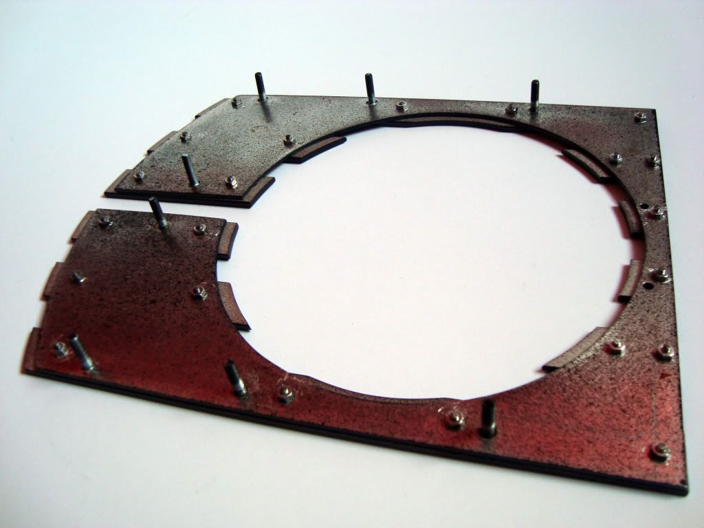
    Backside of the top with all the M2 nuts in place.

    (CLICK TO ZOOM)

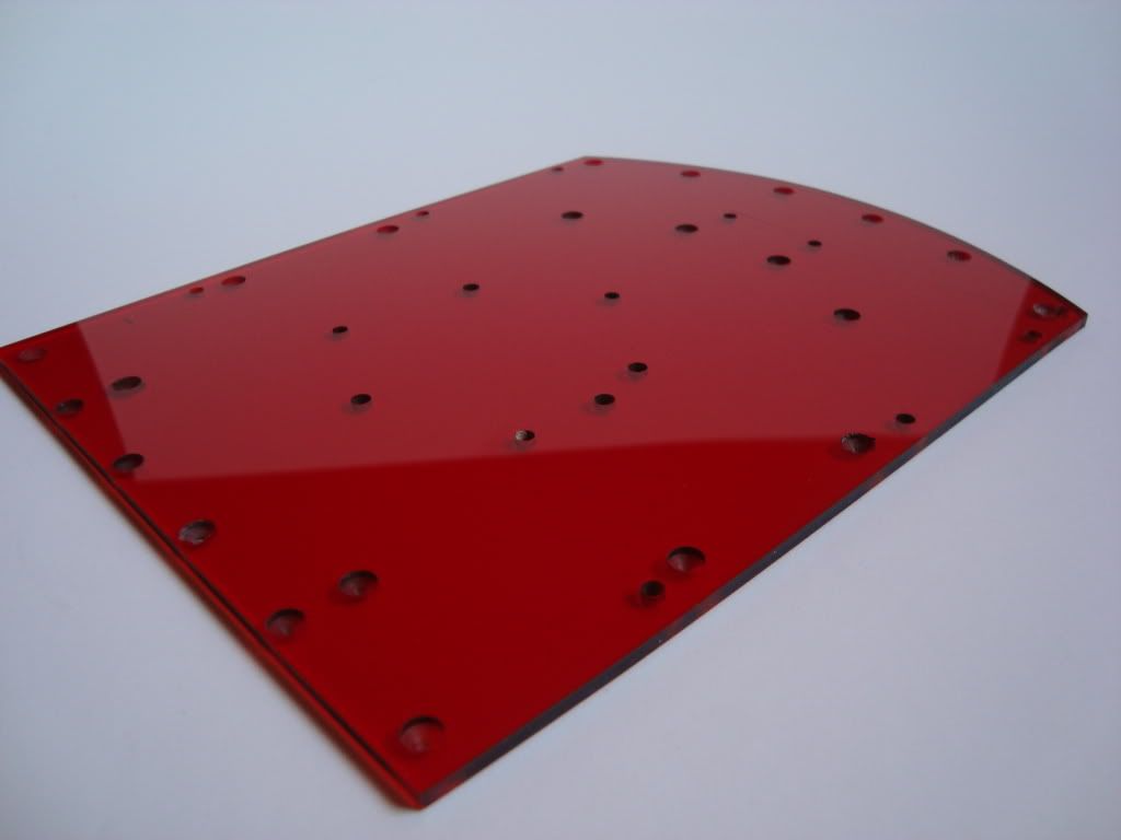
    Plexi being drilled.

    (CLICK TO ZOOM)

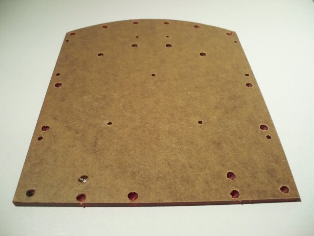
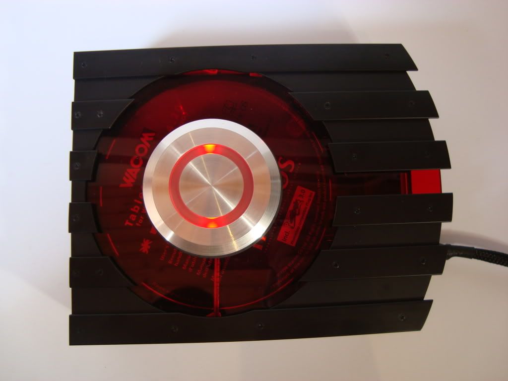
    Some of the holes (the big ones) are not drilled all the way through. This is because they will prevent the bolts from falling in to the drive if they were to come loose but still make room for the M2 bolts when the top and plexi is mounted together.

    (CLICK TO ZOOM)

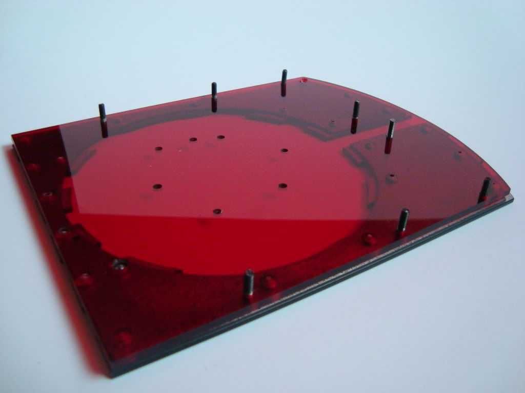
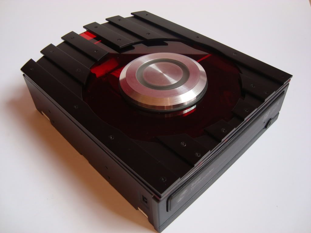
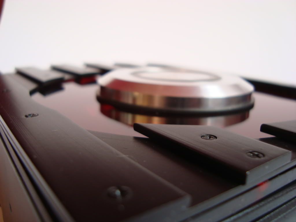
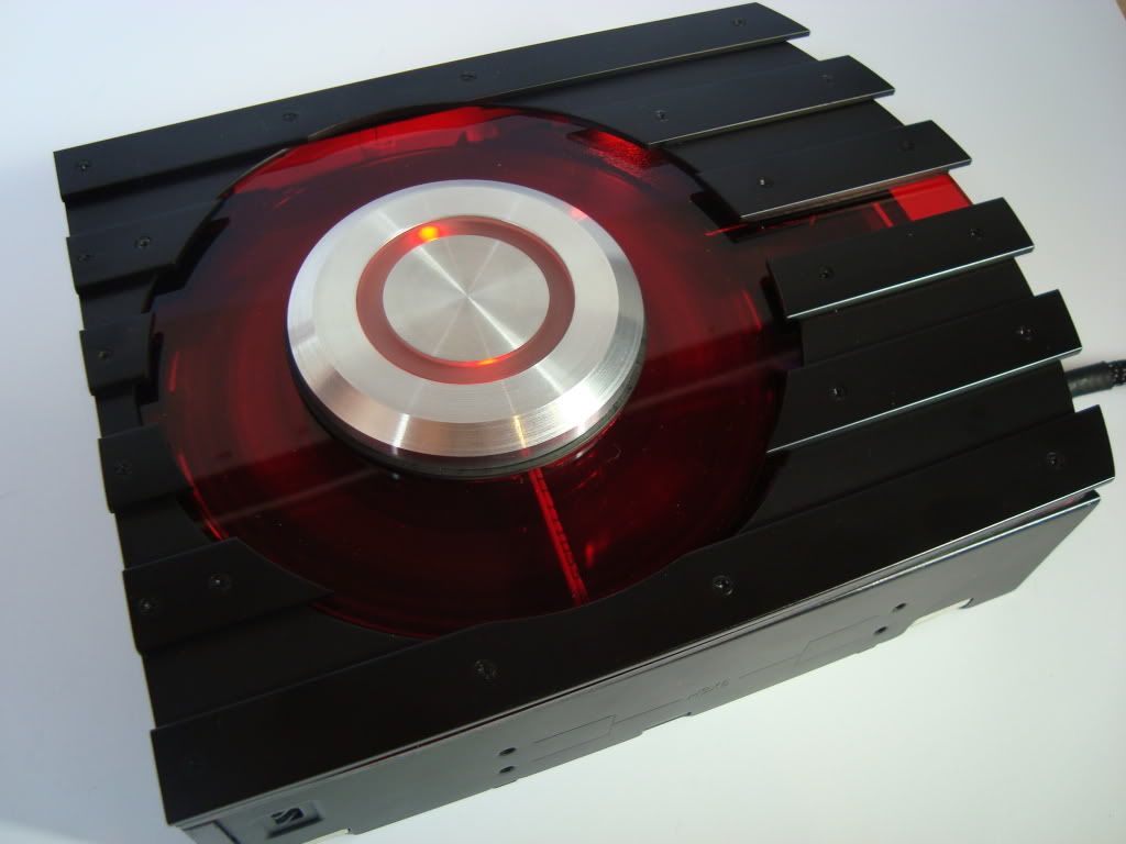
    And here is the top and window mounted together. Here it's easier to see that some of the holes are not drilled all the way through.

    (CLICK TO ZOOM)

    Hope you like it.


    /Gnu
    Last edited by The_Gnu; 12-07-2010 at 12:38 AM. Reason: Update

  2. #2
    Xtreme Guru
    Join Date
    Dec 2009
    Location
    Latvia, Riga
    Posts
    3,972
    I'm looking at those side reservoirs, round window and three round analog gauges (if i'm not mistaken, and those are really some buttons or miniwindows) on front .. you could have gone steampunk way ..
    BTW, speaking of analog gauges. What/which you plan to use there?

  3. #3
    Xtreme Cruncher
    Join Date
    Feb 2008
    Location
    Cincinnati, Ohio
    Posts
    166
    I'm liking what I'm seeing! sub'd
    My Rig
    Case: Corsair Air240
    PSU: Corsair AX860i
    MB: Asus Z270G Strix
    CPU: Intel Core i7 7700K w/Corsair H100i v2
    RAM: 64GB (4 x 16GB) Corsair Vengeance DDR4 3000
    GPU: EVGA GeForce GTX 1070
    SSD: 2 x Samsung 960 Pro - Raid 0
    OS: Windows 10 Pro

  4. #4
    Xtreme Member
    Join Date
    Sep 2007
    Location
    Australia, rAdelaide
    Posts
    268
    Oh man, this is going to be wild!! nice tool choice too
    Last edited by callen_1; 05-24-2010 at 03:00 PM.

  5. #5
    Registered User
    Join Date
    Dec 2009
    Location
    Western Australia
    Posts
    230
    looking nice already and you've barely started, can tell this will be a nice project as im already seeing great attention to detail

    keep it up
    sub'd

  6. #6
    Registered User
    Join Date
    May 2010
    Location
    Sweden
    Posts
    39
    Quote Originally Posted by churchy View Post
    I'm looking at those side reservoirs, round window and three round analog gauges (if i'm not mistaken, and those are really some buttons or miniwindows) on front .. you could have gone steampunk way ..
    BTW, speaking of analog gauges. What/which you plan to use there?
    Your.. spot on. I guess you could kind of call it steampunk without the old copper look. At the moment I got the analog gauges from coolemsater musketer II. (Left - right channel and Hd activity) However im currently searching for some nice analog temp gauges about the same size( 3 - 5cm). Anyone know a place I could get some from?

    Quote Originally Posted by callen_1 View Post
    Oh man, this is going to be wild!! nice tool choice too :uo:
    Quote Originally Posted by erikmorgan View Post
    I'm liking what I'm seeing! sub'd
    Quote Originally Posted by h20xide View Post
    looking nice already and you've barely started, can tell this will be a nice project as im already seeing great attention to detail

    keep it up
    sub'd
    Thanks a lot.. hope you'll like the rest aswell

  7. #7
    Registered User
    Join Date
    Apr 2010
    Location
    France, Paris
    Posts
    39
    We would say a machine as in Jules Verne's novel. I am ready for the odyssey, and I do not leave the screen. Your engineering workshop is already an introduction in the dream.

  8. #8
    Xtreme Member
    Join Date
    Mar 2010
    Location
    UK
    Posts
    284
    Hey,

    This is an exciting introduction to your build, and fantastic work so far. I don't have the patience or tools to craft things by hand! I am really interested in how you came about acquiring the anologue gauges, I have always prefered these over LCD gauges and would love to integrate them into my case.

    Cheers!

  9. #9
    Registered User
    Join Date
    May 2010
    Location
    Sweden
    Posts
    39
    Quote Originally Posted by manu_D View Post
    We would say a machine as in Jules Verne's novel. I am ready for the odyssey, and I do not leave the screen. Your engineering workshop is already an introduction in the dream.
    wow..thx for your first post and the nice comments. Stay tuned and, I'll do my best to make this "novel" readable aswell

    Quote Originally Posted by Mudgey View Post
    Hey,

    This is an exciting introduction to your build, and fantastic work so far. I don't have the patience or tools to craft things by hand! I am really interested in how you came about acquiring the anologue gauges, I have always prefered these over LCD gauges and would love to integrate them into my case.

    Cheers!
    Thanks..I love the analouge way aswell. The gauges that will be on the front of this build are from a coolermaster muskeeteer II. There will be some other aswell, but I havn't aquired those yet.


    Ok
    Time for an update of the DVD progress. This update is about the center ring that will hide the magnetic holder of the disk drive that is needed. It will also contain the Activity LED of the DVD drive. This is also the first real part created by the lathe. Since I yet have to by some aluminium material I had to use what whas laying around.

    In this case. It was an old heatsink

    (CLICK TO ZOOM)


    (CLICK TO ZOOM)


    (CLICK TO ZOOM)

    Starting to take shpe.

    (CLICK TO ZOOM)


    (CLICK TO ZOOM)


    (CLICK TO ZOOM)

    Finished product.

    (CLICK TO ZOOM)

    Milled two slots for the LEDs. These slots will not be visible and therefore I didn't put too much effort in the finish, as you can see. Also M3 holes are drilled and taped for mounting

    (CLICK TO ZOOM)

    The middle disk.

    (CLICK TO ZOOM)

    This is the acrylic LED ring to distribute the light. Some of the parts look rough but this part won't be vissible.

    (CLICK TO ZOOM)


    (CLICK TO ZOOM)


    (CLICK TO ZOOM)

    All parts in there orders. The "wires" are the two red LEDs that will fit in the acrylic ring.

    (CLICK TO ZOOM)

    Here you can see the LEDs mounted in the two slots with some hot glue. The wires are along the sides of the outer aluminium ring.

    (CLICK TO ZOOM)

    This is a piece of difuser plastic and black paper added to help even out the light from the LEDs and make the background colour black when the LEDs are turned of.

    (CLICK TO ZOOM)

    Finished LED ring

    (CLICK TO ZOOM)

    This is the magnetic ring that will be placed on the inside of the plexi window and backside of the LED ring.

    (CLICK TO ZOOM)

    more to come

  10. #10
    Xtreme Addict
    Join Date
    Jun 2007
    Posts
    2,064
    these designs remind me of Bioshock

  11. #11
    Registered User
    Join Date
    May 2010
    Location
    Sweden
    Posts
    39
    Quote Originally Posted by Serpentarius View Post
    these designs remind me of Bioshock
    Without the rust and alga I hope

  12. #12
    Xtreme Member
    Join Date
    Jan 2009
    Location
    colmar, france
    Posts
    458
    i love my job, but guys you rock at what you do, and it makes me feel jealous from time to time (talkin' to you The_Gnu and callen_1 )
    maybe some day i'll have the tools and the skill to do things like that!?
    with all i have in mind, there's a lotta nice rig comin' up (maybe)


    doctor pepper's desk
    EVGA P55 FTW | i5 650 @ 4GHz | 4Gb Corsair Dominator DDR3-1600 XMS3 | XFX 4870 1Gb | Corsair X32 | Samsung SpinPoint F1 - 320Go | Fractal Design Newton R2 650W | Samsung P2450H | Microsoft Laser Desktop 7000 | JBL Spyro Black
    AirCooling: Prolimatech Mega Shadow | Xigmatek Bifrost | Fractal Design SATA Cluster Box | Fractal Design 2x120mm, 2x140mm and 1x92mm

    Cosmos-S
    Foxconn BloodRage Rev1.1 Bios P07 | i7 920 D0 @ 4,629GHz max & 4,3GHz stable | 6Gb Corsair Dominator DDR3-1600 | XFX 5870 | Sonar X-Fi | Intel X25-M 80 Go PostVille | Samsung SpinPoint F1 - 1To | Corsair HX620W | CoolerMaster Cosmos S | Samsung T240 | Logitech MX-5500 & Z-2300
    Watercooling: Laing DDC + plexi top and tank | CPU - HK 1366 rev 3.0 LT | GPU - EK Water Blocks EK FC5870 V2 - Acétal Nickel | MB - Foxconn's original | HDD - HK SilentStar HD-Single rev 2.0 | radiator - 3x120mm | tubing - High Flex 10/16mm | red PrimoChill ICE coolant


  13. #13
    Registered User
    Join Date
    Nov 2008
    Location
    London
    Posts
    32
    Looking good
    My Rig
    Case: Silverstone TJ07B
    Cpu: i7 930
    MOBO: Asus P6T Deluxe v2
    Gpu:None
    Cooling: Air and Dust
    Trying to make big things happen on a small budget

  14. #14
    Registered User
    Join Date
    May 2010
    Location
    Sweden
    Posts
    39
    Quote Originally Posted by josk1 View Post
    i love my job, but guys you rock at what you do, and it makes me feel jealous from time to time (talkin' to you The_Gnu and callen_1 )
    maybe some day i'll have the tools and the skill to do things like that!?
    with all i have in mind, there's a lotta nice rig comin' up (maybe)
    Thanks for the nice comments..I bet you already do doc, ones the will is there there is nothing to stop you. Im actually surprised by how fast its' possible to learn to use tools. There have been many times that I have feel satisfied with a part just to want to remake it a bit later because I know I have learned the tools much better and could do better. Im a bit afraid I will want to remake the case once its done :S. The skills will come with the patience.


    Quote Originally Posted by D1RtY AssASS1n View Post
    Looking good
    Thanks

  15. #15
    Xtreme Member
    Join Date
    Sep 2007
    Location
    Australia, rAdelaide
    Posts
    268
    The dvd mod is looking great, man! I can't wait to see what other crazy stuff you do with your tools!

    BTW that marker sketch of the case front looks awesome, you get any of that inspiration from Chip Foose perhaps?

  16. #16
    Xtreme Member
    Join Date
    Nov 2007
    Location
    Russia
    Posts
    138
    Cool

  17. #17
    Registered User
    Join Date
    May 2010
    Location
    Sweden
    Posts
    39
    Quote Originally Posted by callen_1 View Post
    The dvd mod is looking great, man! I can't wait to see what other crazy stuff you do with your tools!

    BTW that marker sketch of the case front looks awesome, you get any of that inspiration from Chip Foose perhaps?
    Thanks, man. Chip foose.. hm.. nah. Not on this one even thou he creates masterpieces. Did the marker sketch during a class in industrial design. Been doing some car sketches aswell but those arn't even good enough to wipe foose ass.
    Quote Originally Posted by Alexxx650 View Post
    Cool
    thanks

  18. #18
    Registered User
    Join Date
    May 2010
    Location
    Sweden
    Posts
    39
    Almost forgot, a mini-update. This is the internal LEDs that is supposed to light up the interior of the drive. The LEDs are 10mm 800 000 mcd white leads and puts out quite a lot of light. Not the optimal lightsource since I will use a red window that block a lot of the light. Bt these where the ones laying around at the moment. I might change them later if I feel the need.

    I trimmed them down in the mill to be able to fit them on the inside.


    This is the wiring taking power from the backside of the sata-power connector. Not vissible from the front.


    Let there be light

  19. #19
    Xtreme Member
    Join Date
    Mar 2009
    Posts
    143
    excellent! when you start a build with a lathe and mill you know its gonna get good! i really like the led ring idea and cant wait to see what else you have up your sleeve. +1 for leaving some surprises into the build... its way more interesting that way
    Current System:

    Coolermaster HAF 932
    XFX 680i LT SLI Motherboard
    Intel Core 2 Quad Q6600 @ 2.99 GHz
    4 Gb (2x 2Gb) OCZ SLI-Ready RAM
    2x XFX 8800gt XXX edition @ 690/975
    1x 300GB Western Digital Caviar HDD

  20. #20
    Registered User
    Join Date
    May 2010
    Location
    Sweden
    Posts
    39
    Quote Originally Posted by alphadog009 View Post
    excellent! when you start a build with a lathe and mill you know its gonna get good! i really like the led ring idea and cant wait to see what else you have up your sleeve. +1 for leaving some surprises into the build... its way more interesting that way
    Yeah a lathe and mill is a greate addition to the workshop. The possibilities are almost endless of what you can make compared to standard hand tools. Takes some practice and skill though.


    It's about time to finish this DVD drive so I can continue with the rest of the case.

    Here is the LED ring again if you forgotten about it.

    (CLICK TO ZOOM)

    It is mounted to the outside of the drive window with the magnetic disc holder on the inside. All the taped holes are lined up and screwed together in place using three hex screws.

    (CLICK TO ZOOM)

    The wire for the LED ring is feed along a cut channel in the plastic on the internal case (red circle) and feed through to the other side of the case where it is soldered to the original LED connections.

    (CLICK TO ZOOM)


    (CLICK TO ZOOM)

    The whole case is assembled and the dvd drive is finaly done.

    (CLICK TO ZOOM)


    (CLICK TO ZOOM)


    (CLICK TO ZOOM)

    Yay it works...

    (CLICK TO ZOOM)


    (CLICK TO ZOOM)

    Doing a testspinn with a disk.. and it works fine.

    (CLICK TO ZOOM)


    (CLICK TO ZOOM)

    As you can see the red plexi blocks out some of the light from the White led's, but that was expected. These photos where taken in bright daylight with sun shining in to the room. Therefore it was hard to get a fair picture of the light. The LED ring light is much more evenly lit in reality. Next time I'm at the workshop I will try to get a couple of nightshots to show the lighting better..

    There you have it, the result of way to much time spent on a DVD drive. But anyway I'm satisfied with the result and I hope you like it.

    Time for the rest of the case..

  21. #21
    Xtreme Member
    Join Date
    May 2009
    Location
    Tennessee
    Posts
    158
    Nice work man.
    Cosmos S
    Core i7 920 3.9GHz
    6GB Corsair Dominator DDR3 1600
    EVGA GTX 285
    X-fi Forte
    WD VR 300GB
    EVGA x58 MB

    LC Loop
    Swiftech GTZ
    Swiftech MCR-320 Radiator
    Swiftech MCP655
    EK Multi option reservoir
    Feser 1/2" ID tubing (AWESOME)

  22. #22
    Registered User
    Join Date
    May 2010
    Location
    Sweden
    Posts
    39
    Quote Originally Posted by Rumpus01 View Post
    Nice work man.
    Thanks..

    Time for some nightshots
    It was really hard to capture the true effect of the led light. The real color is too red for the camera to pic up and it gets a more orange color. This is really anoying Because the light is a nice deep red in reality. Untill I get hold of a better camera (tried 2 already) these pics will have to do.

    Drive bay open...

    (CLICK TO ZOOM)

    ..and closed, with the activity LED ring flashing.

    (CLICK TO ZOOM)

    Time to show some progress of the chassi work. Won't say much exept that I know that some of the bits and pieces could probably have been made in a much more effective way. When creating this case I have realised that using 90 degre L profiles can sometimes result in some complications e.g in the corners. Next time I vill most likely use solid square rods to save some time and headache.

    Anyway here are the pics..

    Some alu L bar reshaping in the mill..

    (CLICK TO ZOOM)


    (CLICK TO ZOOM)

    When trying to pop rivet the parts together I realized there was a slight broblem. Couldn't get in to the base with the plier...

    (CLICK TO ZOOM)

    I had to use the lathe to create a small extender out of steel.. If you create something like this you will have to make shure it is not too long since then the plier won't get a good grip of the rivet. This is about as long as my plier can handle.


    (CLICK TO ZOOM)

    And it works like a charm and I have been using it on almost all rivets since most of them are in cramped places.


    (CLICK TO ZOOM)


    (CLICK TO ZOOM)

    Here is the internal bottom side plate and its mounting brackets. One of them is black because it was part of a previous solution that once it was painted, turned out not to work. Don't worry, the rest of the case parts will allso be painted and anodized black once they are all done.

    (CLICK TO ZOOM)

    This is part of the PSU holder riveted in place...

    (CLICK TO ZOOM)

    ..and here is the other part of the psu holder mounted in the chassi.

    (CLICK TO ZOOM)

    Bottom plate brackets mounted in the chassi..

    (CLICK TO ZOOM)

    ..and here the bottom plate has been added.

    (CLICK TO ZOOM)

    The bottom plate will be mounted using M3 nutts. That means the 1,5mm thin L brackets that will hold the plate needs to bee threaded. And since I often screw up those threads, because I can't hold the thread tap in a 90degree angle, I did this little tool. I used my drillpress to drill a 90degree hole, the same size as the tap, in a spare peace of aluminium

    (CLICK TO ZOOM)

    Now the thread tap is always 90degree to the hole and the threads are perfectly straight. Very usefull for thin materials where you only have one try..

    (CLICK TO ZOOM)

    PSU backplate being fabricated the good old style..

    (CLICK TO ZOOM)


    (CLICK TO ZOOM)

    Riveted in place..

    (CLICK TO ZOOM)

    Time for a test fit of the PSU.. it's a 580w Hiper-R for those wondering.

    (CLICK TO ZOOM)


    (CLICK TO ZOOM)

    And here it is from the back. The Fan guard is Removed as you can see but will be added later along with the mounting holes for the PSU

    (CLICK TO ZOOM)


    (CLICK TO ZOOM)

    Hope you like it.
    All comments and criticism are more than welcome.[/QUOTE]

  23. #23
    Registered User
    Join Date
    May 2010
    Location
    Sweden
    Posts
    39
    Btw.. It seems like I can't edit the Thread title that is displayed in the worklog section. The title is changed in the thread but not when viewed from the "outside" keeps saying "23- may" or is that just for mee?.

    Any ideas on how to solve this?

  24. #24
    Xtreme Member
    Join Date
    Mar 2009
    Posts
    143
    looks good! i like the backplate for the bottom part but was wondering how you were gonna hide the cables cuz i see no holes through the plate but im probably being an idiot and missing something.... or you probably just have a better idea.
    Current System:

    Coolermaster HAF 932
    XFX 680i LT SLI Motherboard
    Intel Core 2 Quad Q6600 @ 2.99 GHz
    4 Gb (2x 2Gb) OCZ SLI-Ready RAM
    2x XFX 8800gt XXX edition @ 690/975
    1x 300GB Western Digital Caviar HDD

  25. #25
    Registered User
    Join Date
    Dec 2009
    Location
    Western Australia
    Posts
    230
    Quote Originally Posted by The_Gnu View Post
    Btw.. It seems like I can't edit the Thread title that is displayed in the worklog section. The title is changed in the thread but not when viewed from the "outside" keeps saying "23- may" or is that just for mee?.

    Any ideas on how to solve this?
    still says 23- may here too mate

    No clue

    But this build is certainly coming together very nicely

Page 1 of 3 123 LastLast

Tags for this Thread

Bookmarks

Bookmarks

Posting Permissions

  • You may not post new threads
  • You may not post replies
  • You may not post attachments
  • You may not edit your posts
  •