Page 2 of 3 FirstFirst 123 LastLast
Results 26 to 50 of 68

Thread: Project: ProtoHype - 23 may

  1. #26
    Registered User
    Join Date
    May 2010
    Location
    Sweden
    Posts
    39
    Quote Originally Posted by alphadog009 View Post
    looks good! i like the backplate for the bottom part but was wondering how you were gonna hide the cables cuz i see no holes through the plate but im probably being an idiot and missing something.... or you probably just have a better idea.
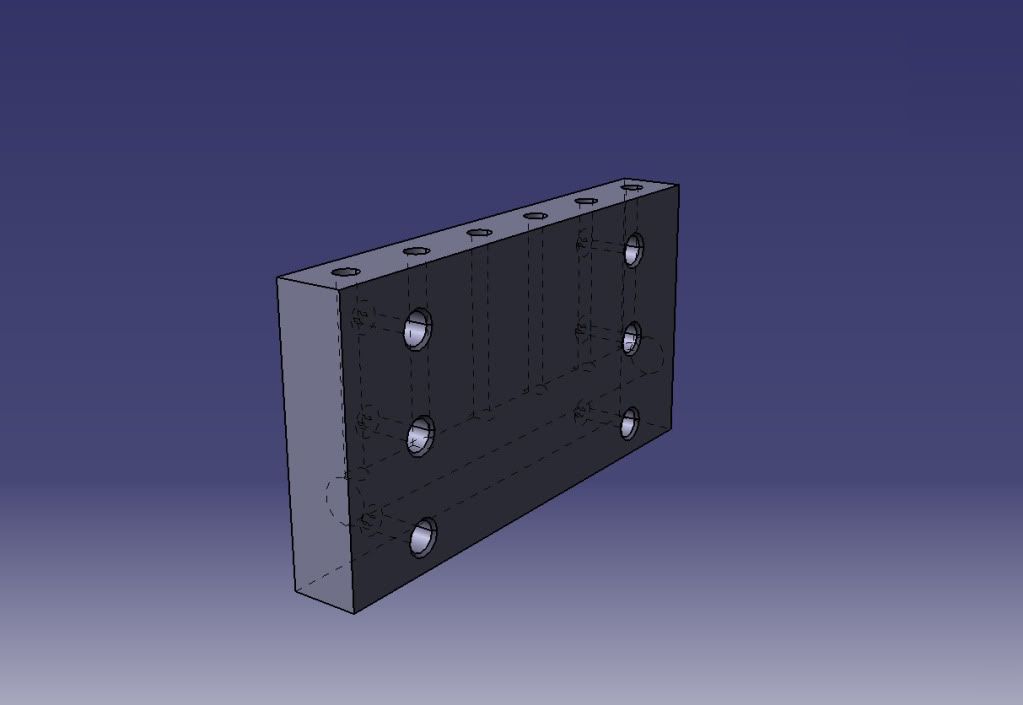
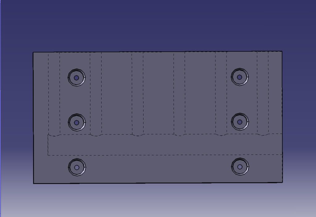
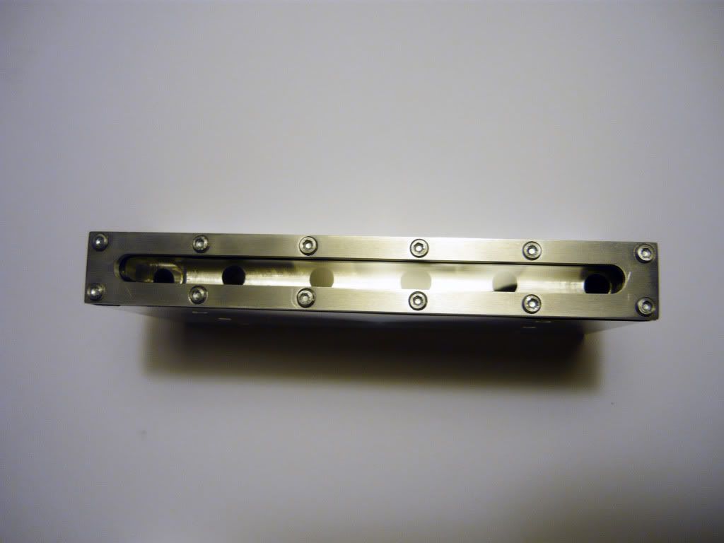
    thanks.. na your not an idiot, it's just me that havn't realy decided where to place the holes yet. There will be holes somewhere for shure. At the moment im thinking of routing the cables down through the bottom of the chassi and through one of those alu profiles. Hard to describe but it will come clear eventually.

    Quote Originally Posted by h20xide View Post
    still says 23- may here too mate

    No clue

    But this build is certainly coming together very nicely
    Thanks mate

  2. #27
    Xtreme Member
    Join Date
    Feb 2010
    Posts
    224
    Looks like this could be stunning! keep it up! more updates!

  3. #28
    Registered User
    Join Date
    May 2010
    Location
    Sweden
    Posts
    39
    Quote Originally Posted by imersa View Post
    Looks like this could be stunning! keep it up! more updates!
    thanks

    *EDIT: oops.. managed to mix the pictures with the last update, so here are the real pictures

    it is time to improve the rigidity of the case. Especially the part where the DVD-drive and the harddrives + harddriveblocks will be mounted. This is mainly becasue I reallised that there will be some serious weight and stress on some of the parts and I want to make shure that it alls stays stable

    Finally, there is some milling.
    But first I need some material. This is the two aluminium squareblocks I purchased for this build. The dimentions are 20x200x1000mm and 10x200x1000mm and almost all of it will be used in this build.

    (CLICK TO ZOOM)

    (CLICK TO ZOOM)

    Some of the 10mm alu was cut..

    (CLICK TO ZOOM)

    Clamped in the vice and the milling could begin.

    (CLICK TO ZOOM)


    (CLICK TO ZOOM)

    First milling session is done.

    (CLICK TO ZOOM)

    Test fitting the support brackets...

    (CLICK TO ZOOM)

    ..and realised that I need some room for some connections.
    Wha that board's for?.. well you'll have to wait and see if you can't figure it out by your self..


    (CLICK TO ZOOM)

    The groove is taking shape.

    (CLICK TO ZOOM)


    (CLICK TO ZOOM)

    Drilled some holes on the other support brackets as well and some adjustments with the mill

    (CLICK TO ZOOM)

    Now there is enough room for the connections..

    (CLICK TO ZOOM)


    Rivet in place from the backside

    (CLICK TO ZOOM)


    (CLICK TO ZOOM)

    This is how I cut the pannels. Using a jigsaw annd an alu ruller.

    (CLICK TO ZOOM)

    As I predicted, there was some nasty gap between the pannel and the motheroard tray (to the right in the picture). Even though it probably won't be vissible once the Motherboard is mounted, I can't stand the knowledge of it being there.

    (CLICK TO ZOOM)

    Fabricated a small part from an L-alu part using the mill. I thought for shure it would bend in the middle but I managed to pull it of. The reason it is black is because I't was intended for another use and since the whole case will be black, it won't matter.

    (CLICK TO ZOOM)

    This is how it will be mounted..with rivets.

    (CLICK TO ZOOM)

    Test fitting the panel

    (CLICK TO ZOOM)

    now thats better..

    Drilled some holes and did some taping and here the plate is testfitted using m3 hex-bolts. Those hex-bolts stand out cuite a lot and they are only there temporarely. Will change them to some flat head screws.

    (CLICK TO ZOOM)

    there you go.
    Last edited by The_Gnu; 06-29-2010 at 12:44 PM. Reason: wrong pictures

  4. #29
    Xtreme Member
    Join Date
    Nov 2007
    Posts
    268
    i smell a mdpc in the works...
    [SIGPIC][/SIGPIC]

  5. #30
    Xtreme Member
    Join Date
    Sep 2007
    Location
    Australia, rAdelaide
    Posts
    268
    More brilliant work! Are those mills relatively easy to use?? it looks like you can do so much cool stuff with them!!

    The fix for the gap in the mobo tray turned out fantastic too

  6. #31
    Registered User
    Join Date
    May 2010
    Location
    Sweden
    Posts
    39
    Quote Originally Posted by geoffsthaboss View Post
    i smell a mdpc in the works...
    Thanks mate

    Quote Originally Posted by callen_1 View Post
    More brilliant work! Are those mills relatively easy to use?? it looks like you can do so much cool stuff with them!!

    The fix for the gap in the mobo tray turned out fantastic too
    Thanks, Yeah these mills are easy to use. The precission is very great and your fingers are kept safe . There is also the possibility to mod most mills to your own desires, like DIY digital read outs. Only bad thing about these mills that exept the cost for the mill itself, you need a lot of tools and acessories to be able to do a large variety of stuff. What you can do and how precise it is, is often limited by the acessories. Another drawback with my mill is the belt drive, it takes a lot of time to change the speed. a mill with gearbox is better but often more expensive.

    God luck

  7. #32
    Registered User
    Join Date
    May 2010
    Location
    Sweden
    Posts
    39
    okay, sorry for my abcense but I have to say I don't feel too enthusiastic to keep posting updates while the title of my log still says 23 may. I've tried to contact moderators but with no luck. Anyone know of a moderator that might be worth sending a PM?


    Well heres the next update.

    This is the part Im about to fabricate next, it is the top (and bottom) of the case as you probably already figured out.

    (CLICK TO ZOOM)

    This is how the finished parts hopefully will look. It's a quite advanced shape, atleast I think so. Since I don't have acess to a CNC, the rounded surfaces will be a pain in the ass to fabricate

    (CLICK TO ZOOM)

    This is the profile of the bars and the support for them. The bottom of the bars and the support might look a little bit unnecessarily complex. The reason for this is that there will be alumium mesh added between the rods and this will probably make it a little bit more easy to install. There is also the airflow in mind. The support will probably still see some modifications to ease the fabrication, if you know of any, please let me know since I'm still learning.

    (CLICK TO ZOOM)

    This is how I intendt on creating the curve. Milling the parts in a stair patern and then even out the curved surface by hand with a file. This is the only solution I have to the problem at the moment, please let me know if you got a better one that will save me some elbow grease.
    I was thinking of fabricating my own cutter with the desired radius but I would need to fabricate 3 different ones and also a tool to create them.

    (CLICK TO ZOOM)

    Picked up some aluminium square rods last week. The thickness is 20mm and it was delivered in 6 X 1m lengts.

    (CLICK TO ZOOM)

    The first thing to do was to cut them all down to 50cm lengts.

    (CLICK TO ZOOM)

    At this point I'm starting to realise how much this case will weigh...a lot

    (CLICK TO ZOOM)


    (CLICK TO ZOOM)

    Since the rods are 20mm square, I need to mill them down 2mm since I want them to be 18 mm. I could have bought 18mm square rods from the beginning but since (half) of these rods will be on the top of the case and very vissible, I wan't them to be perfect. There is almost always some dents or large scratches from the metal supplier and therefore I prefer to have some excess material.
    Btw this is one of the mills at school that I finally have acess to, not my own. This one is much larger and there is a lot of nice tools. Like this facemill.

    (CLICK TO ZOOM)

    I also discovered a second vice wich helped me speed up the facemilling process a lot, since there is a total of 24 sides that need to be treated.

    (CLICK TO ZOOM)

    I ran out of time and had to stop after half of the pieces where done. This is what I got so far.

    (CLICK TO ZOOM)


    (CLICK TO ZOOM)

    See ya

  8. #33
    Registered User
    Join Date
    May 2010
    Location
    Sweden
    Posts
    39
    Hello
    I have had some alignment problems with the mill im currently using at school and therefore the toprods have ended up taking longer to fabricate than estimated. For that reason I have also started the work on some other parts of the project to speed up the process a bit. This is the work currently done on the top rods

    all 12 rods and 24 sides are facemilled and ready for the rough milling.


    (CLICK TO ZOOM)


    (CLICK TO ZOOM)

    Here is the first rod taking shape. Each step has a different depth to create the a rough shape of the desired radius.


    (CLICK TO ZOOM)


    (CLICK TO ZOOM)


    (CLICK TO ZOOM)

    This is suposed to bee one of the underside of the rods. Managed to screw it upp a bit because the previously mentioned alignment problems with the vices. Think I managed to save it though.

    (CLICK TO ZOOM)

    The work on the toprods are on hold untill I manage to solve the problems with the vices.
    Therefore I started working on the HD-blocks that are a lot less problematic to fabricate.

    This is the plan for the HD blocks. Two solid Alu blocks that will cool up to three hard drives. The water will enter the top block and continue on to the second block through a single tube and then exit the second block through 6 separate tubes.


    (CLICK TO ZOOM)

    Layout of the top block. The middle "plate" is supposed to be a plexi window to add to the geekyness. There will also be a thin sheat of rubber to (hopefully) make it leak proof.


    (CLICK TO ZOOM)

    Sideview of the top block, here you can see the chanel structure


    (CLICK TO ZOOM)

    Bottom block, with chanel structure.


    (CLICK TO ZOOM)


    (CLICK TO ZOOM)


    Time for fabrication.
    First of I need some thick pieces of alu. These are 160x20mm and cut with an angle grinder


    (CLICK TO ZOOM)


    (CLICK TO ZOOM)

    Using an endmill to trimm the edges and make it the right dimentions.


    (CLICK TO ZOOM)


    (CLICK TO ZOOM)


    (CLICK TO ZOOM)


    (CLICK TO ZOOM)


    (CLICK TO ZOOM)


    (CLICK TO ZOOM)

  9. #34
    Registered User
    Join Date
    May 2010
    Location
    Sweden
    Posts
    39
    So... my work with the HD blocks continues
    I discovered that the two alupieces I've previously cut were not totaly flat. They had a slight curve on them and therefore needed some treatment. The curve was from the manufacturing process so if you plan on buying anything like this, it's a good thing not to buy the exact dimension since this seems to be quite common. I used the 4-jaw chuck, on the lathe wich alows me to attach non cirkular workpieces.


    (CLICK TO ZOOM)

    Have to make shure to keep those fingers out of the way.


    (CLICK TO ZOOM)

    Here you can se the curve of the pieces. The center part is beeing romeved first while the edges are left untouched and this is because the curve.


    (CLICK TO ZOOM)

    After some passes the piece is nice and flat. Flipped it over an did the same on the other side.


    (CLICK TO ZOOM)

    To bad they will probably not stay this shiny during the rest of the working. Well...will probably have to redo the surface once finished.

    (CLICK TO ZOOM)


    (CLICK TO ZOOM)


    (CLICK TO ZOOM)

    Here I'm starting to drill the channels in one of the blocks. They will be threaded with M8 threads later and therefore I used a 7mm drill. 6,8 is the optimal drill for this thread but I didn't have that one so this will have to do. The depth of the holes are 60mm.

    (CLICK TO ZOOM)


    (CLICK TO ZOOM)


    Flipped the pieces over and started to drill the holes for the HD mounting. I used a 4mm drill to drill all the way through.


    (CLICK TO ZOOM)

    For those of you thinking of doing somethings similar, the long distance between the holes are 101,6 mm which is standard for 3,5" HDD.


    (CLICK TO ZOOM)

    Here I use a 8,5 mm drill to make room for the head of the HD mounting screws. These holes are not drilled all the way through.


    (CLICK TO ZOOM)


    (CLICK TO ZOOM)


    (CLICK TO ZOOM)


    (CLICK TO ZOOM)

    Time to start threading with the M8 tap. The alu piece with a hole in it is the guid tool I made to make shure the thread starts taping at a 90degree angle.


    (CLICK TO ZOOM)


    (CLICK TO ZOOM)


    (CLICK TO ZOOM)

    Also did some edge chamfering of the holes to give it a nicer look. Here you can se that the large hole is not all the way through since it leaves 2mm in the bottom to make the screws pop out enough on the mounting side.


    (CLICK TO ZOOM)


    (CLICK TO ZOOM)


    (CLICK TO ZOOM)


    (CLICK TO ZOOM)

    There is still the largest intake hole, some mounting holes and surface treating left to do but you get the idea.

  10. #35
    Xtreme Addict
    Join Date
    Jan 2003
    Location
    Macomb Twp MI
    Posts
    1,221
    I wana move into your house!
    Running now, http://www.evga.com/forums/tm.aspx?m=693435

    Intel 3960 @ 5Ghz
    Asus Rampage IV Extreme
    QuadFire 7970
    X-Fi Sound Card
    16GB G.Skill 2133Mhz DDR3 Quad Channel Ram 9,11,10 @ 1.65v.
    3 Acer 23" 3D Ready LCDs
    2x Ultra X4 1600 WATT P/S 's
    MM Extension Ascention UFO Case W/ Top of the line Water cooling. Dream build!

  11. #36
    Registered User
    Join Date
    Oct 2008
    Posts
    40
    WOW, amazing work here! Keep it up, I am looking forward to the updates.

  12. #37
    OVERCLOCKAHOLICS
    Join Date
    Jul 2010
    Location
    Hawaii
    Posts
    858
    Now here is something that merits a WOW! Thanks for the update!

    OCM

  13. #38
    Xtreme Enthusiast
    Join Date
    Oct 2004
    Location
    Canada
    Posts
    763
    holy cow, awesome!
    Lian Dream: i7 2600k @ 4.7Ghz, Asus Maximus IV Gene-z, MSI N680GTX Twin Frozr III, 8GB 2x4GB Mushkin Ridgeback, Crucial M4 128GB x2, Plextor PX-755SA, Seasonic 750 X, Lian-li
    HTPC: E5300@3.8, Asus P5Q Pro Turbo, Gigabyte 5750 Silentcell, Mushkin 2GBx2, 2x 500gb Maxtor Raid 1, 300gb Seagate, 74gb Raptor, Seasonic G series 550 Gold, Silverstone LC16m

    Laptop: XPS15z Crucial M4
    Nikon D700 ~ Nikkor 17-35 F2.8 ~ Nikkor 50mm F1.8
    Lian Dream Work Log
    my smugmug
    Heatware

  14. #39
    Registered User
    Join Date
    May 2010
    Location
    Sweden
    Posts
    39
    Quote Originally Posted by eclypse View Post
    I wana move into your house!
    Haha no you don't. I live in a small apartment far away from the tools unfortunately. Some work you see is done at my mums house (my tools though) and the larger machines you might see in some updates are from my schools workshop.

    Quote Originally Posted by Fyrelith View Post
    WOW, amazing work here! Keep it up, I am looking forward to the updates.
    Quote Originally Posted by OC Maximus View Post
    Now here is something that merits a WOW! Thanks for the update!

    OCM
    Quote Originally Posted by Jokester_wild View Post
    holy cow, awesome!
    Thanks a lot guys.. Hope you'll like the rest aswell :P

  15. #40
    I am Xtreme
    Join Date
    Feb 2003
    Location
    Netherlands
    Posts
    6,421
    Wowsers! Looking good!!
    Asus Crosshair V Formula-Z | FX 8350 | 2x4GB Trident-X 2600 C10 | 2x ATI HD5870 Crossfire | Enermax Revo 1050watt | OCZ Vertex 3 60GB | Samsung F1 1TB

    Watercooling: XSPC Raystorm | EK 5870 Delrin fullcover | TFC X-changer 480 w/ 4x Gentle Typhoon | DDC2+ Delrin top | EK 200mm res | Primochill LRT 3/8 tubing

    Case: Murdermodded TJ-07

    sub 9 sec. SPi1M 940BE 955BE 965BE 1090T

  16. #41
    Xtreme Addict
    Join Date
    Feb 2010
    Location
    Wisconsin
    Posts
    1,634
    Very clean cuts you got there.
    Signatures make my posts look huge... but I'm not humble enough to completely remove my signature, so I kept this note explaining it.

  17. #42
    Registered User
    Join Date
    May 2010
    Location
    Sweden
    Posts
    39
    Quote Originally Posted by Zeus View Post
    Wowsers! Looking good!!
    Thanks

    Quote Originally Posted by ScottALot View Post
    Very clean cuts you got there.
    Thanks..I try my best. I Meassure 2-3 times before cutting to to avoid misshaps, but that still doesn't prevent some misstakes from happening :S

  18. #43
    Xtreme Member
    Join Date
    Mar 2008
    Location
    Finland
    Posts
    250
    Insane. Subscribed.
    Not into xtreme builds anymore, just like to keep things silent.
    Asus P6T Deluxe V2 - Intel i7 920 3.6 GHz - 6 Gb 1800 MHz DDR3 - AMD HD5850

  19. #44
    Xtreme Addict
    Join Date
    Feb 2010
    Location
    Wisconsin
    Posts
    1,634
    Quote Originally Posted by The_Gnu View Post
    Thanks..I try my best. I Meassure 2-3 times before cutting to to avoid misshaps, but that still doesn't prevent some misstakes from happening :S
    Measure twice, cut once!
    Signatures make my posts look huge... but I'm not humble enough to completely remove my signature, so I kept this note explaining it.

  20. #45
    Registered User
    Join Date
    May 2010
    Location
    Sweden
    Posts
    39
    Quote Originally Posted by Lagaaja View Post
    Insane. Subscribed.
    Nice.. thanks

    Quote Originally Posted by ScottALot View Post
    Measure twice, cut once!
    Ehm..yeah I wish twice was enough

  21. #46
    Xtreme Member
    Join Date
    Jun 2007
    Location
    Bloomington, IN
    Posts
    208
    Looking nice, keep up the good work

  22. #47
    Registered User
    Join Date
    May 2010
    Location
    Sweden
    Posts
    39
    Quote Originally Posted by rocket733 View Post
    Looking nice, keep up the good work
    Thanks. I'll try


    With one of the Hd-blocks almost done, its time to start the work on the next one. This one will be a little bit more of a challenge than the previous one since it will require a lid with a leakproof sealing. The plan is to seal it with a rubber gasket but I've been told that an O-ring seal is better. However using an o-ring on this block would require a total makeover of the block since ther isn't enough room (as you'll see in the pics later). I decided to give the rubber gasket a shot and see if it's possible. If its not.. well I'll have to redo it.

    First of I cutt a slot with a 6mm endmill. This is to make things a little bit easier for the final 8mm mill. The slot was made in several steps to get to the desired depth of 10mm.


    (CLICK TO ZOOM)


    (CLICK TO ZOOM)


    (CLICK TO ZOOM)


    Here I've milled the slot again with a 8mm end mill.


    (CLICK TO ZOOM)


    (CLICK TO ZOOM)

    When milling slots that is as wide as the cutter, one of the sides tend to get a nice finish, while the other side gets pretty rough. This is because of the milling direction. To get a nice finish on both sides, I milled it over once again while taking a very small cut about 0,05mm of the rough edge. This left the nice side untouched and smoothed out the rough side. If you look closely you can se the fine line between the rough and smooth surface right on the left of the mill.


    (CLICK TO ZOOM)


    (CLICK TO ZOOM)


    (CLICK TO ZOOM)


    (CLICK TO ZOOM)

    Drilling 2,5mm holes that for the M3 threads


    (CLICK TO ZOOM)


    (CLICK TO ZOOM)


    (CLICK TO ZOOM)

    Again.. my little taping tool to keep the holes at a 90deg angle.


    (CLICK TO ZOOM)


    (CLICK TO ZOOM)


    (CLICK TO ZOOM)

    All M3 threads done. Here you can se that there is almost no space left to fit an O-ring as I mentioned eralier. Lets just hope I can get it sealed enough with the rubber gasket. I'm afraid it might be a bit tricky...but hey. it's worth a shot.


    (CLICK TO ZOOM)

    Here I'm drilling the internal channels for the whater to pass through.


    (CLICK TO ZOOM)

    This shot you better enjoy because I was doing the drilling while taking a picture and it almost messed up the whole part. The drill managed to slip a little bit in the beginning and created some ugly marks by the top of the hole as you can se in the last photo of this post.. I was seriously thinking of redoing the whole part because of that, but I swallowed my pride and perfectionism and decided it will have to do.


    (CLICK TO ZOOM)

    Drilling some mounting holes, similar to the ones on the previous block.


    (CLICK TO ZOOM)


    (CLICK TO ZOOM)

    And there you have it... the two blocks together. I still got the water in/out channels left to drill on both of them.


    (CLICK TO ZOOM)


    (CLICK TO ZOOM)

    Here you can see the drillslip mark I was talking about. Third hole from the top on the left piece....Gaah it hurts to know that it's there.

    (CLICK TO ZOOM)

  23. #48
    Registered User
    Join Date
    May 2010
    Location
    Sweden
    Posts
    39
    I have been trying to fabricate the top for the HD block. The hardest part was, as expected, to create the rubber gasket and make it able to provide a leakproof seal. I first tried by cutting a gasket from a sheat of rubber but soon abandoned that idea to try the luck with silicone. The silicone was also hard to use since I would need to be able to remove the silicone once set, and that wasn't easy without destroying the silicone. This ended up with a leaking seal and I decided to give another shot at cutting a rubber gasket. The second time it turned out much better and this is the method I'm sticking with at the moment. I still have to hard test it for leeks while applying real pressure since I've only been testing it with the pressure my lungs are able to produce .

    Anyway... Here are the pictures of the last parts for the HD blocks in the making.
    Sorry for the crapy quality of the first 4 pictures. I forgot my real camera at home and had to use the "light identifier" also known as "camera" on my nokia 5310.


    (CLICK TO ZOOM)


    (CLICK TO ZOOM)


    (CLICK TO ZOOM)


    (CLICK TO ZOOM)


    (CLICK TO ZOOM)


    (CLICK TO ZOOM)


    (CLICK TO ZOOM)


    (CLICK TO ZOOM)


    (CLICK TO ZOOM)


    (CLICK TO ZOOM)


    (CLICK TO ZOOM)


    (CLICK TO ZOOM)


    (CLICK TO ZOOM)


    (CLICK TO ZOOM)


    (CLICK TO ZOOM)


    I couldn't keep myself from modding the screws just a tiny bit. Gave them a treatment in the lathe to make them a littlebit smaller and give them a more edgy look.

    (CLICK TO ZOOM)


    (CLICK TO ZOOM)


    (CLICK TO ZOOM)


    (CLICK TO ZOOM)


    (CLICK TO ZOOM)


    (CLICK TO ZOOM)


    (CLICK TO ZOOM)


    (CLICK TO ZOOM)


    Had to do some test fitting with some old harddrives. Fits like a glove but dang this thing turned out heavy


    (CLICK TO ZOOM)


    (CLICK TO ZOOM)

    There you have it... the HD blocks are done, (apart from the finishing surface treatment later on). Now it's time to work on the rest of the build.

    /GNU

  24. #49
    Xtreme Addict
    Join Date
    Feb 2010
    Location
    Wisconsin
    Posts
    1,634
    go ahead and watercool the psu while you're at it!
    Signatures make my posts look huge... but I'm not humble enough to completely remove my signature, so I kept this note explaining it.

  25. #50
    Registered User
    Join Date
    May 2010
    Location
    Sweden
    Posts
    39
    Quote Originally Posted by ScottALot View Post
    go ahead and watercool the psu while you're at it!
    Actually, I did some tests regarding that yesterday. Either heatpipe or watercooling was my thoughts but it turns out that one of the heatsinks of the PSU is live (240V). Therefore I think I'll leave the modding of the PSU. But maybe I'll give it a try if I can figure something out or find a PSU without live heatsinks.

Page 2 of 3 FirstFirst 123 LastLast

Tags for this Thread

Bookmarks

Bookmarks

Posting Permissions

  • You may not post new threads
  • You may not post replies
  • You may not post attachments
  • You may not edit your posts
  •