

Wow! Sick work so far, keep it up!

Matt Black
Shiny Silver
Black Sparkle

Wow! Sick work so far, keep it up!
thankksOriginally Posted by xxrabid93


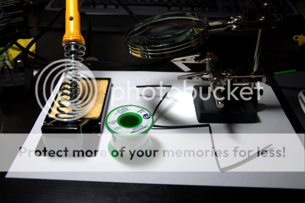
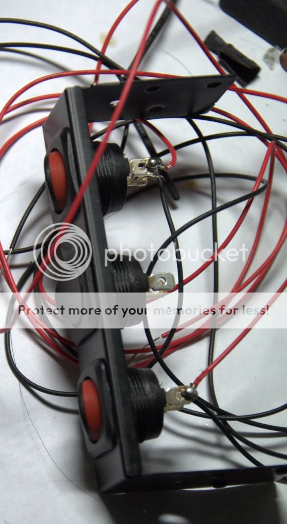
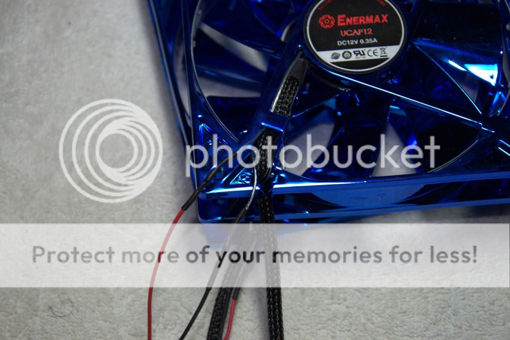
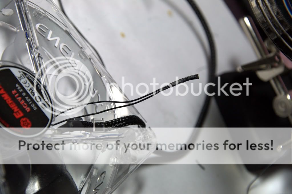
Well couldnt find a way to join two fan wires to make them longer without soldering. At the end, I have no choice:
Could anyone explain this?
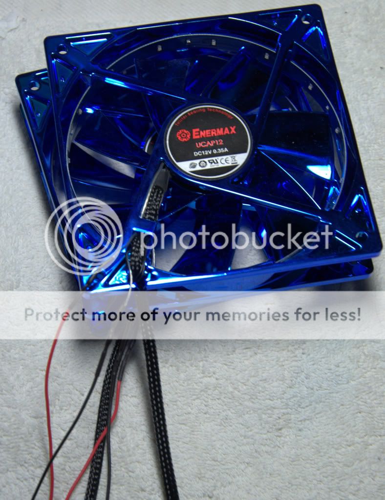
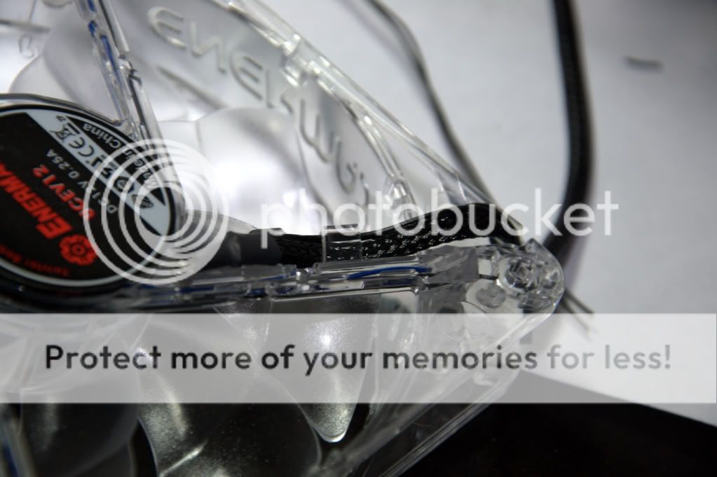
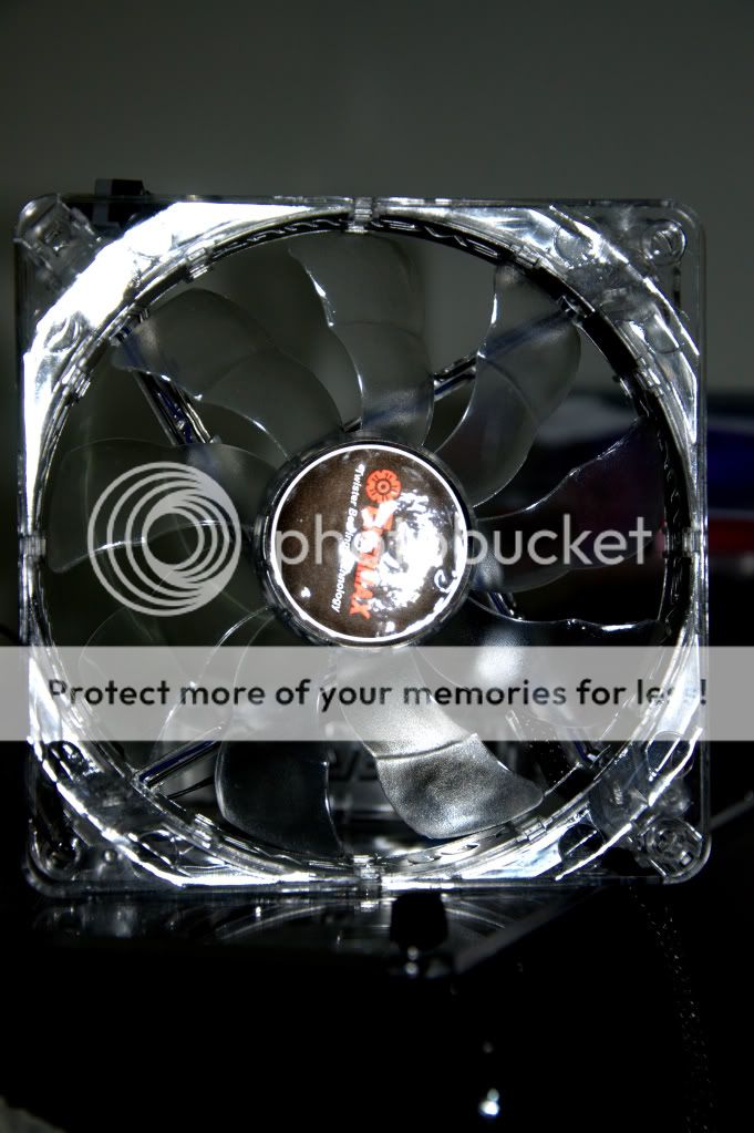
I got 4 in 1 fan wires
and why does only one of them has three pins while other 2 has pins? Whats the purpose of yellow wire?
The one with black, red and yellow had a sticker attached "with fan speed signal"? I am scratching my head now. The reason I am asking this I just want to know what I am doing.


yellow is the rpm sensor wire
Main: i7-930 @ 2.8GHz HT on; 1x GIGABYTE GTX 660 Ti OC 100% GPUGrid
2nd: i7-920 @ 2.66GHz HT off; 1x EVGA GTX 650 Ti SSC 100% GPUGrid
3rd: i7-3770k @ 3.6GHz HT on, 3 threads GPUGrid CPU; 2x GIGABYTE GTX 660 Ti OC 100% GPUGrid
Part-time: FX-4100 @ 3.6GHz, 2 threads GPUGrid CPU; 1x EVGA GTX 650 100% GPUGrid
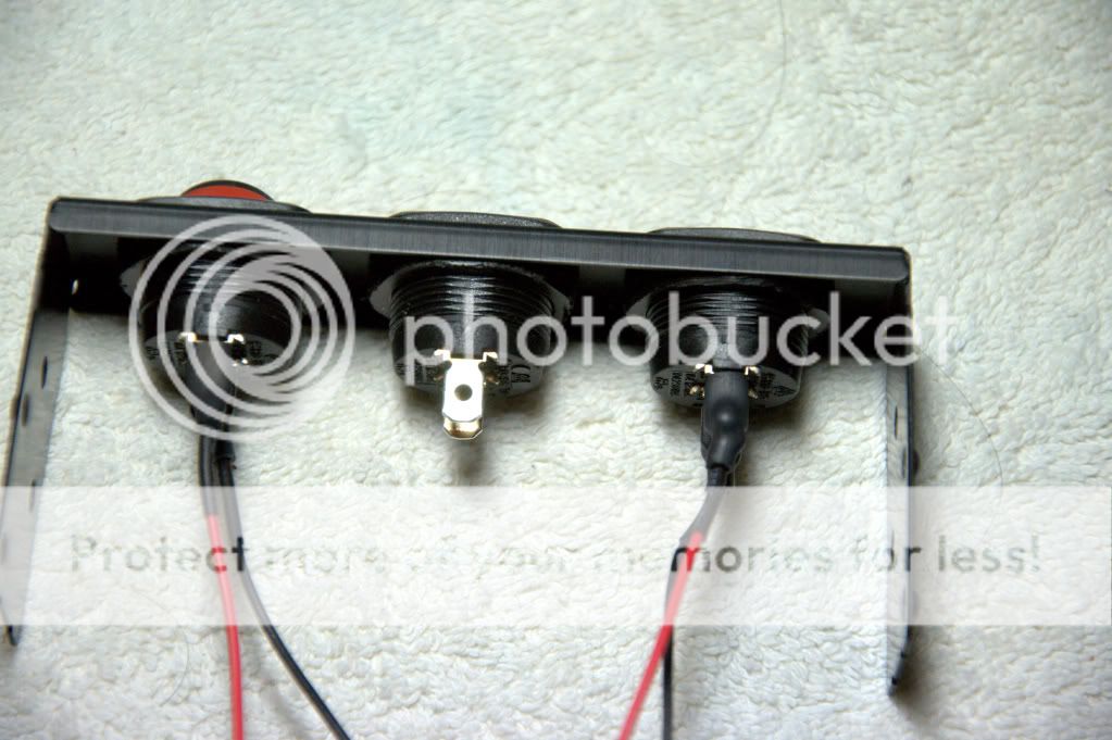
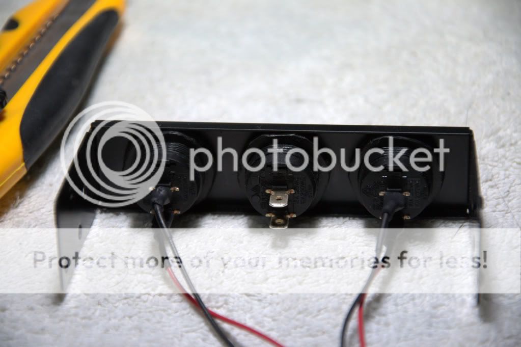
Switch for fans LED
Last edited by marxviper; 06-08-2010 at 08:53 AM.

As stated above, the yellow wire is the RPM wire, it produces a signal via a hall effect sensor on the fan blades which is counted to produce RPMs, you can only sense one of your 4 fans correctly, wiring up 4 yellow in parallel will not work. Judging from your picture, it appears you have done everything correctly.
One hundred years from now It won't matter
What kind of car I drove What kind of house I lived in
How much money I had in the bank Nor what my cloths looked like.... But The world may be a little better Because, I was important In the life of a child.
-- from "Within My Power" by Forest Witcraft
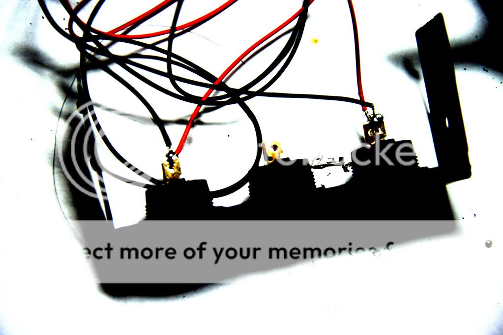
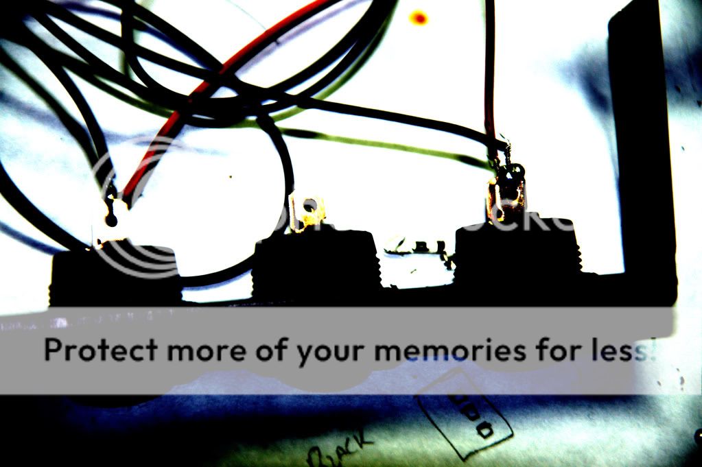
I would suggest re-soldering the switch contacts. You have little balls of solder, what that looks like to me is you heated the solder but not the metal tab itself, so the solder did not "flow" onto the tab. It may feel solid now, but potentially unreliable.
Yeah, definitely resolder -- a little flux on the tab as well probably would help given the condition of the tab as it stands.
One hundred years from now It won't matter
What kind of car I drove What kind of house I lived in
How much money I had in the bank Nor what my cloths looked like.... But The world may be a little better Because, I was important In the life of a child.
-- from "Within My Power" by Forest Witcraft
Also, make sure to heat the tab, not the wire. You should not be touching the iron directly to the solder but instead let the solder flow on to the tab and then on to the wire.
Yup -- the solder should 'wet' or 'flow' into the tab/wire much like water wicking up into a paper towel.
Soldering is not hard, but it does take a bit of practice to get good at it.
One hundred years from now It won't matter
What kind of car I drove What kind of house I lived in
How much money I had in the bank Nor what my cloths looked like.... But The world may be a little better Because, I was important In the life of a child.
-- from "Within My Power" by Forest Witcraft
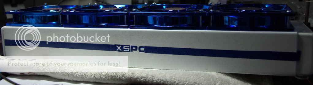
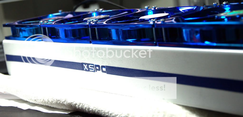
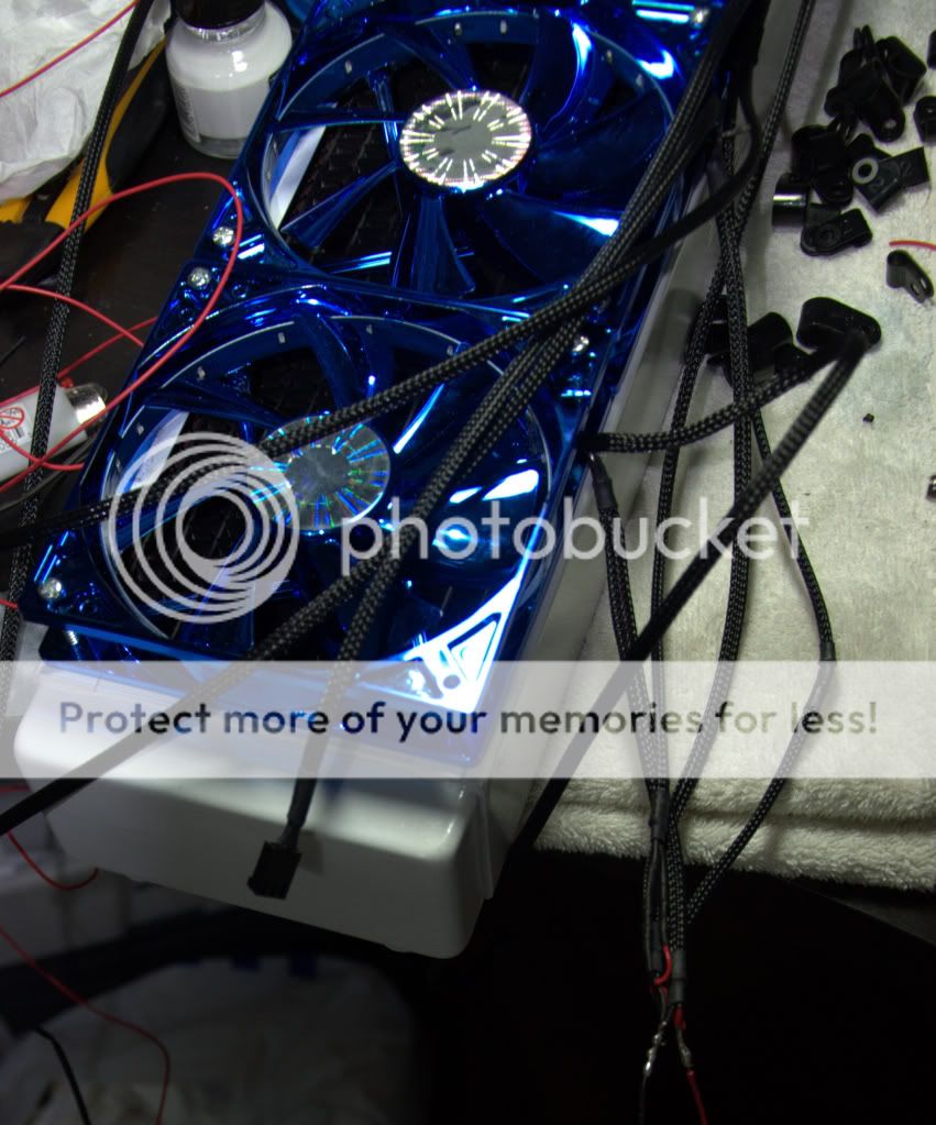
blue fans and white rad kinda goes well
LED wires extended and covered with heat shrinks
Switches with heat shrinks
Painted them white and messed up a bit, pics of bay drives gonna be uploaded later.
Joined the heat sensor wires together and they run faster now. Now I would just control the speed by the fan controller.
To Be Continued.....
Last edited by marxviper; 06-15-2010 at 04:10 PM.
I hope you haven't installed this set of wires in this state. At a minimum cover those separately.
Also it looks like you have that wire too stranded. If you twist the end between your fingers and then create a crook in both wires you're connecting and loop them inside each other you can get a much cleaner solder joint. After that make sure to wrap them in electrical tape or something similar so that your case doesn't catch on fire from a short.
The joints you have there are gooped up with solder which indicates that you didn't get the wires hot enough to actually melt it evenly. It really just looks like that joint could break apart with a slight tug.
I'm pretty sure he's going to use heat shrink to cover it....
Windows 7 64 Bit
BenQ FP241W Black 24" LCD
Mountain Mod Case w/ Base
Asus Rampage III Black Edition
i9-990x @ 4.58GHz - 1.36v Temps (Idle 23C - Load 48C)
12GB Corsiar Dominator GT (PC3 15000) @ 9-9-9-24 1T - 1.65v
Sapphire 5870 x3 "OC" w/ EK Water Block Temps (25C-49C)
EK-Supreme / 4 Alphacool Laing DDC-Pump Ultras + Extras
Power Supply / 2x Silver Stone DX1000
Western Digital 1.0TB x 3
Crosair SSD 128GB x 2
World Community Grid!
That won't keep the joint from coming apart and it won't make the connection any more solid. It will keep sparks from happening though
I agree.... He's learning...
Windows 7 64 Bit
BenQ FP241W Black 24" LCD
Mountain Mod Case w/ Base
Asus Rampage III Black Edition
i9-990x @ 4.58GHz - 1.36v Temps (Idle 23C - Load 48C)
12GB Corsiar Dominator GT (PC3 15000) @ 9-9-9-24 1T - 1.65v
Sapphire 5870 x3 "OC" w/ EK Water Block Temps (25C-49C)
EK-Supreme / 4 Alphacool Laing DDC-Pump Ultras + Extras
Power Supply / 2x Silver Stone DX1000
Western Digital 1.0TB x 3
Crosair SSD 128GB x 2
World Community Grid!
Thank you for your advice.
I did heat the wire up but I just put too much solder just to make sure. I tugged them really hard too. And they didnt break apart
I am planning to put heat shrinks on them (double heat shrinks)
By the way, how to clean the soldering iron? it takes ages to heat them up.
I have you guys to teach me
Thanks
Take an old sponge and drip some water on it. While it's hot quickly drag the tip of the iron along the sponge. You should be pulling the iron across the sponge. Also you may want to tin the iron, which means putting a little bit of solder on the tip of the iron before you start on a solder joint, just enough for the hot part to turn silver from solder. This will help you to find the hot part of the tip if it isn't a great iron and will make the actual melting of solder faster. When putting it into storage put a blob of solder on the tip to keep it from oxidizing, it will melt off easily the next time you go to heat it up.
Thanks for the tip
Yep, what he described is called tinning the tip. You can also tin the wires before you actually try to make the solder joint itself.
Take one of the two wires you are wanting to join, dip it in some liquid flux not quite touching the insulation. Press the tip of the iron against the bare wire and hold your solder on the opposite side.
Whent he wire heats enough the flux will begin to bubble and the solder will melt and wick into the wire. The trick once you see the wicking action is to pull the solder away within a short amount of time to avoid 'flooding' the wire.
Do this to the other wire.
Tinning the wires holds the strands together firmly, I then lay the wires parallel, opposite facing and do about a 1/2 twist. I then touch the iron to the wires until the solder of the tinned wires melt. This welds them together without need for more solder. If it looks a bit weak, you could also touch the solder to the 1/2 twist as you heat it.
I will be doing the same thing as you are soon, if helpful I will post a play-by-play set of pix for you.
Jack
One hundred years from now It won't matter
What kind of car I drove What kind of house I lived in
How much money I had in the bank Nor what my cloths looked like.... But The world may be a little better Because, I was important In the life of a child.
-- from "Within My Power" by Forest Witcraft
No problem, my parents are paying good money for my electrical engineering degree so I can post helpful comments for other people on forums
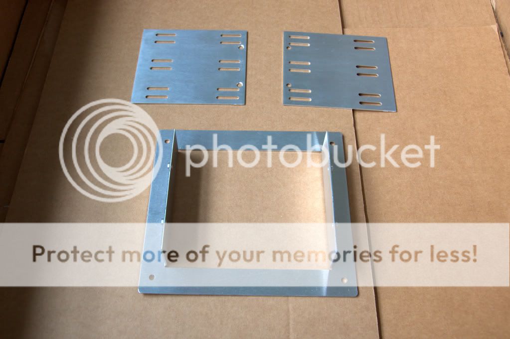
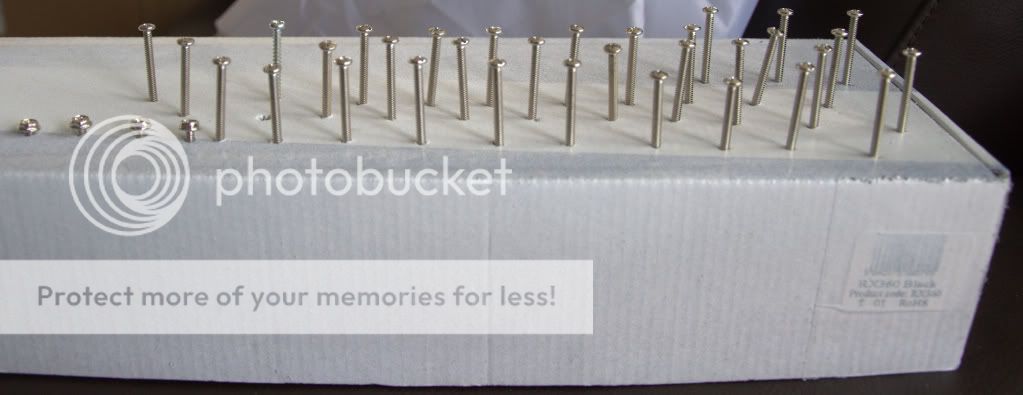
I need your opinion on this pic:
what do you think of this side panel of 5.25" bay?


 Reply With Quote
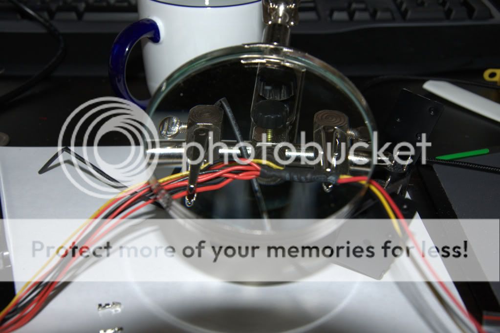


Bookmarks