


Note: (Major buildlog update shortcuts at bottom of this first post)
The contest and the components
Earlier this month, ASUS Computer created a contest called “ASUS Xtreme Design”,
calling on computer enthusiasts to showcase their concepts on what kind of unique systems they could imagine and build,
leveraging ASUS main components and their accompanying technologies to their advantage.
20 winners were chosen from phase 1 (concept phase).
I was chosen as one of the 20 winners of the concept phase.
Now begins phase 2 (build phase) of the contest,
where the other 19 winners and I are building their systems with the components provided by ASUS and the other contest sponsors,
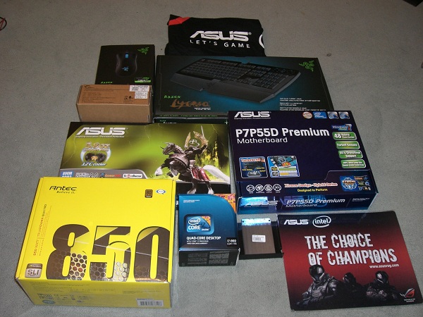
this is to thank and showcase the contest sponsors:
ASUS, First and foremost, for putting on the contest:
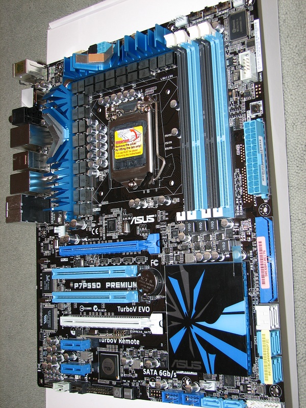
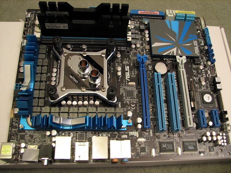
ASUS P7P55D Premium motherboard-
A very sexy looking motherboard (MOSFET heatsinks look awesome),
including full speed SATA 6Gbps ports, 32 phase CPU power design (!),
Fan Xpert (motherboard fan control, 1xPWM, 2x voltage control),
integrated ExpressSSD for internet access almost instantly/without booting to Windows,
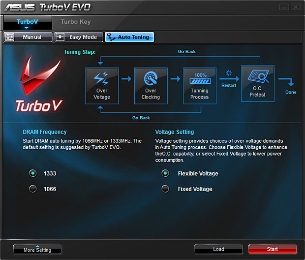
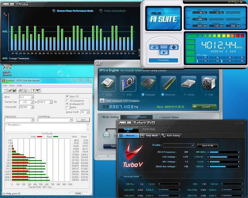
hybrid power management, autotune overclocking , external overclocking remote.
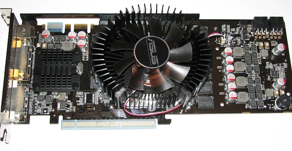
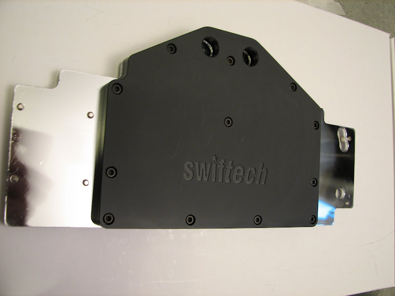
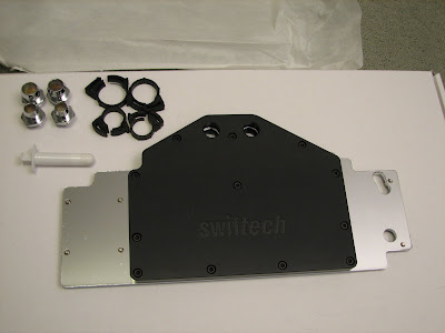
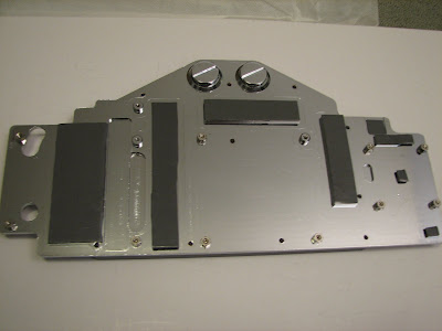
ASUS Nvidia GTX260 GL+ (55nm Core 216) video card-
This card uses a GTX275 PCB, newer 55nm GPU fabrication process, and non-reference “copper core” fan.
I will be swapping out the included HSF for a full cover water block, detailed later.
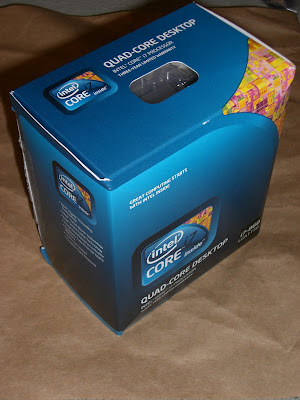
Intel Core i7-860 CPU-
Latest LGA 1156 socket, Hyperthreading for more CPU efficiency in many programs,
more turbo boost and less power consumption than the Core i7-900 series.
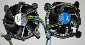
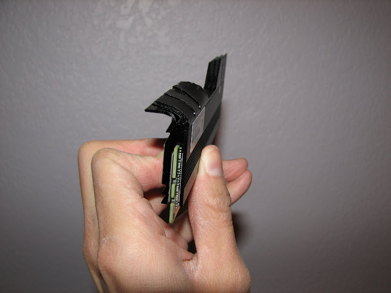
Comes with a woefully inadequate fan in retail boxed version
(picture compares E8xxx Core 2 Duo to Core i7-860 HSF)..
I do like the smaller/less bulky retail box though, seems more efficient, even in packaging.
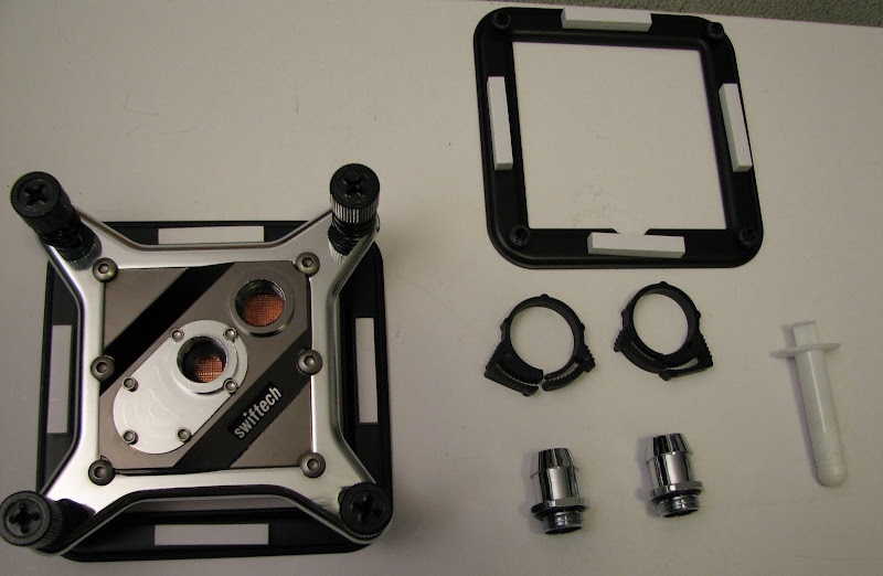
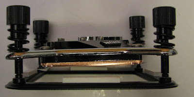
Stock HSF will be replaced with a water block for better cooling performance under overclocking conditions,
as well as more freedom in system packaging (no tall “tower” air HSF to deal with.
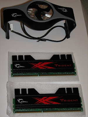
G.Skill 4GB (2 x 2GB) DDR3-2133-
Since LGA 1156 only supports dual channel DDR3 memory, (LGA 1366 supports triple channel),
the 2133Mhz transfer speed will provide plenty of memory bandwidth to feed data to the hungry 8-threaded CPU with Intel turbo boost.
This memory kit comes with some nice looking heatspreaders and a dedicated fan to cool the memory.
I won’t be utilizing the fan for a couple reasons- I don’t think DDR3 gets hot enough to require both a fan and a heatspreader,
I will have enough case airflow blasting the memory to keep it cool enough anyways, and my case design is already fairly limited on internal volume.
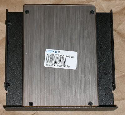
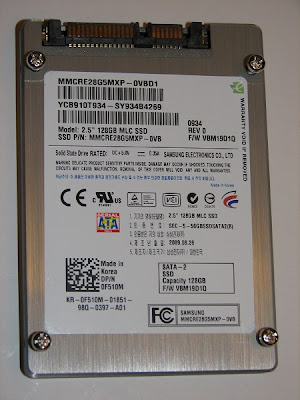
Samsung 128GB SSD-
Extreme disk access speed, both in sequential throughput and random accesses.
Faster boot times, faster game and program load times, but trade off in total storage space.
In the computer storage hierarchy, it is in between DRAM and magnetic disk platter (HDD);
SSD access is faster than HDD, but more expensive per GB than HD...
DRAM is even faster access than SSD, but more expensive per GB than SSD.
I will include some other SSDs or possibly a HDD in my system for more mass storage space.
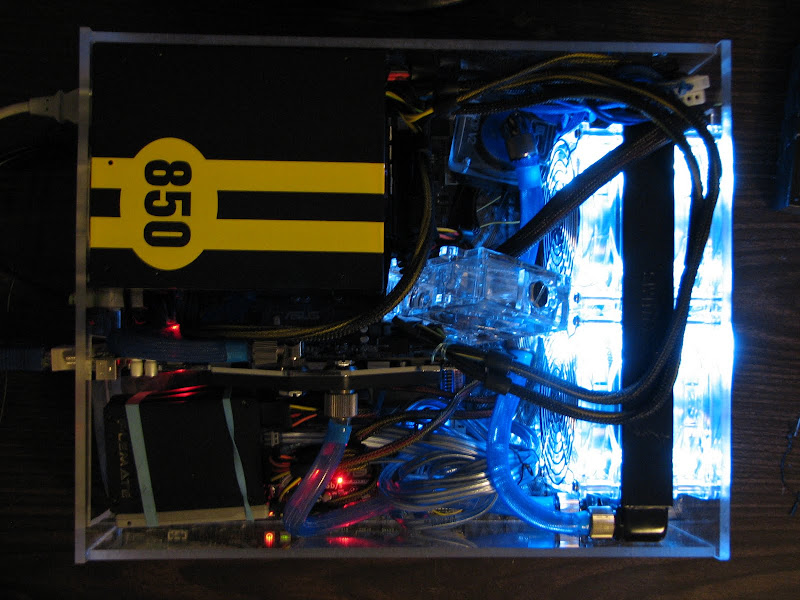
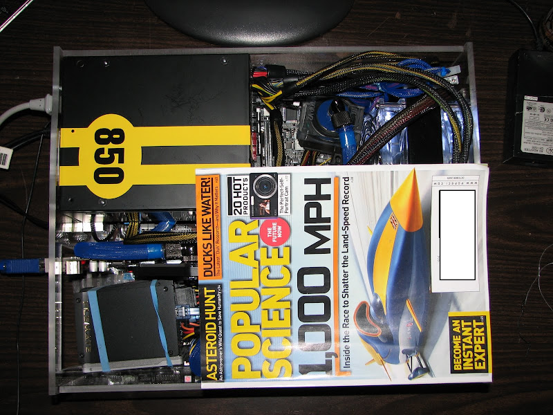
Antec Quattro 850W Power supply –
<PSU pic>
850watts, 80+ bronze efficiency rating, nice looking black and yellow “race car” stripes/number paint design,
modular cables to reduce clutter and thereby improve airflow (essential for a small case design as mine).
What’s not to like?
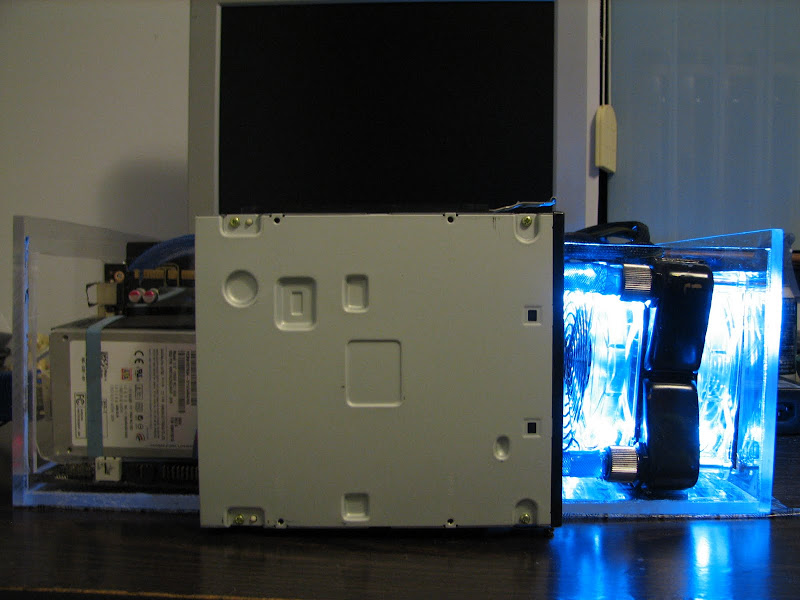
This PSU only has an 80mm cooling fan on the rear, and intake ports on the front,
unlike many power supplies that now have a 120+mm fan on the bottom of the PSU and vents on the rear.
This could be a good or bad thing for your case airflow, depending on how yours is designed.
Note that the smaller fan is not an indicator of less power, but rather greater efficiency.
A large portion of the PSU interior is taken up by a massive heatsink to cool the interior components.
Because of this large heatsink, this PSU is also notably longer than a standard ATX power supply,
so be aware of the extra length clearance required, if you are considering it for your build.
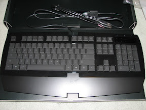
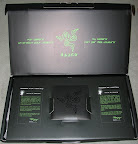
Razer Lycosa Keyboard and mouse-
For the gaming community we have an 1800 dpi mouse, and a nice keyboard to match.
Keyboard has some tack to the keys, to help your fingers “grip” the keys and not slide around on the key surface.
Keyboard has short throw keys like a laptop keyboard, but the action feels very precise.
Keyboard also includes USB port and audio connectors on the back side of the keyboard, a nice convenience if your case is sitting on the floor or more than arm’s reach away from you.
Mouse is very accurate and has the same “tack” feel as the keyboard.
Lots of black.
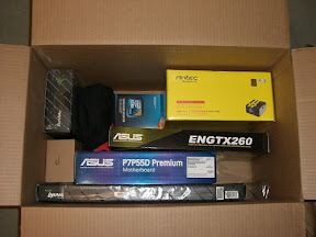
UPDATE: Monday 11/23/2009
The parts arrive! The 30 day build timeline has started!
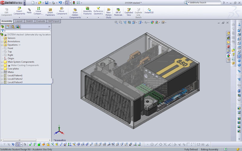
Here is a summary of my design concept:
My design concept is to build a small form factor gaming system for use in a Home theater environment, to maximize portability and minimize wasted space, without giving up expansion or upgrade options.
Here were my design requirements:
1. Keep components cool and system stable 24/7/365, even while overclocking.
2. Keep the whole system quiet, to allow for use in a home theater-type environment.
3. Design to allow future upgradability.
4. Minimize wasted space. I don’t need 5x DVD-ROMs, 8x 3.5” HDD, etc,. Plus a massive “box” wouldn’t look good next to modern consumer electronics- LCD or Plasma TV, Home theater surround sound amplifier, etc,.
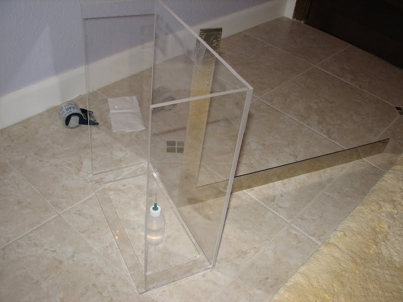
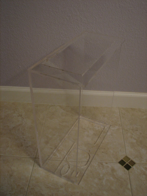
Here is my concept design, dimensions are: 400mm x 319mm x 146mm
Using 3/16” thickness acrylic for all walls.
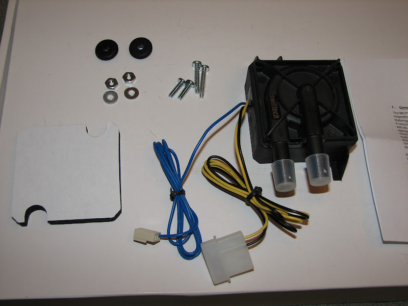
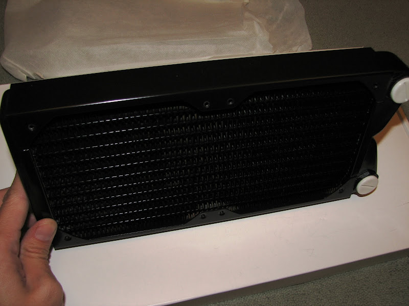
Watercooling for CPU and GPU in a single loop with 240mm radiator.
PSU mounting above CPU area, since this is a water cooling-only case, I don’t need any clearance for HSF.
This does require 90 degree elbow fittings into and out of the CPU water block, though.
UPDATE: 12/03/2009 Another system build primary sponsor!
http://www.xtremesystems.org/forums/...98#post4137957
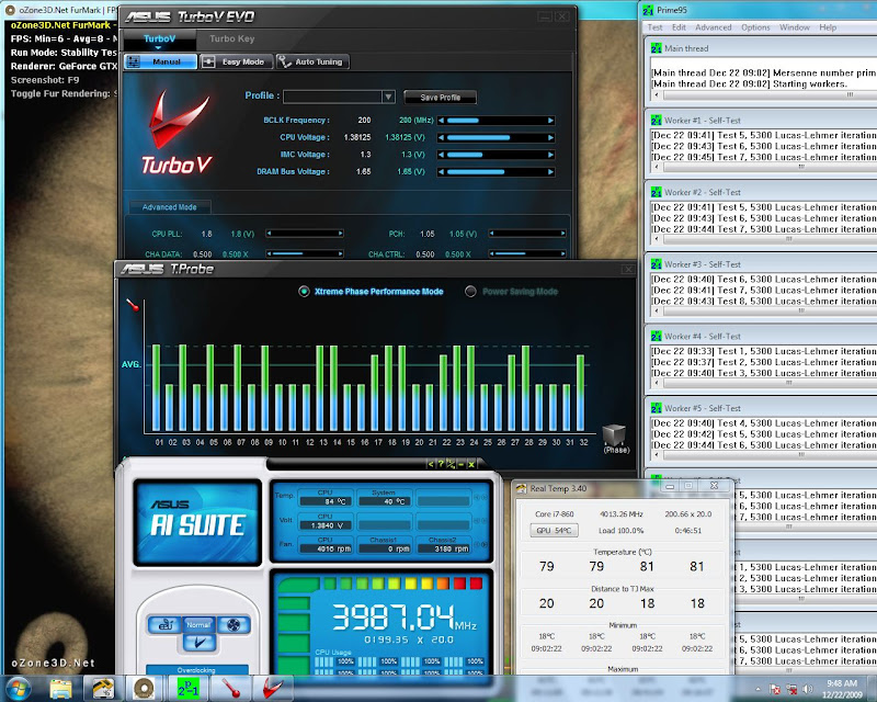
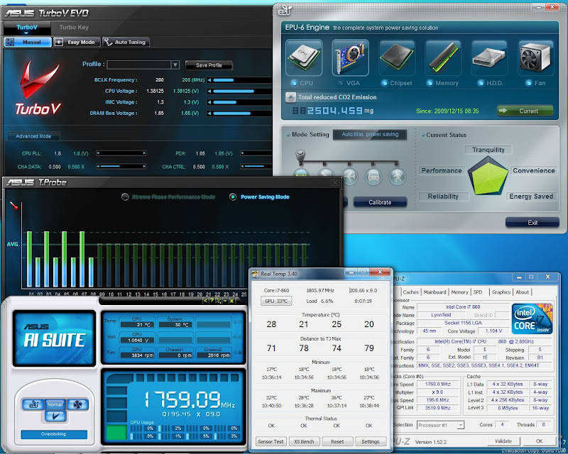
UPDATE: 12/19/2009 4.4Ghz reached!
http://www.xtremesystems.org/forums/...98#post4163104
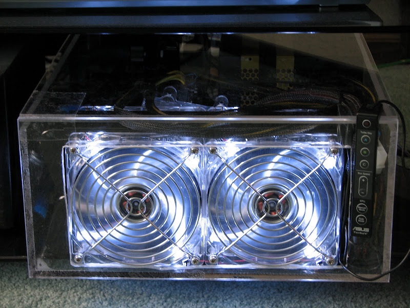
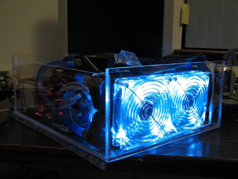
UPDATE: 12/24/2009 "White Dwarf" is built and running!
http://www.xtremesystems.org/forums/...90#post4170290
UPDATE: 12/25/2009 "White Dwarf"youtubed
http://www.youtube.com/watch?v=SB2YDt2kdqo


 Reply With Quote
 and welcome to XS.


Bookmarks