

Nice, oo and purple different
what colour will you be doing the tubing and LED's will you introduce any other colours?
and woooo prince


Nice, oo and purple different
what colour will you be doing the tubing and LED's will you introduce any other colours?
and woooo prince
My Computer
Parts:
CPU: Q9450 @ 3.6Ghz(OC'd)1800Mhz FSB
Mobo: EVGA 780i
GPU: HD 5870 (I have two but only got one in at the moment)
PSU: 1000w Corsair
Ram: 4GB Corsair dominator DDR2 1066Mhz
Soundcard: Asus Xonar D2
Monitor: Samsumg 226BW 22" and secondary 17" LCD
Speakers: logitech Z5400
Case: Tj07 fully sleeved wires
Water cooling:
Loop 1: Mobo NB & Mofset with Zalman resorator
Loop 2: CPU (Ek supreme) with MCP 355 XSPC acrylic top 360 & 240 mm rad
A bit about me
My Worklog
looking great along...very nice work so far...
I Was Exactly thinking the same thingOriginally Posted by Semicycle

but it's a very nice paint job
Duality: Q9550 - P5Q Deluxe - 8GB OCZ - HD5850 - 4,64TB WD - HX650 - X-fi - Aquaero 4 - Lian Li V1000b II Plus @Dual loops watercooling
Loop 1 => DDC18w w/ EK X-top V2 - EK Supreme HF - EK FC5850 - PA120.3 - Multires 150
Loop 2 => DDC18w w/ EK X-top V2 - PA120.1 - MIPS mosfet 1&2 - mips NB - Mips Ramfreezer 4 - MIPS SB - Multires 150
I think it's not a bad color and now it is painted, it is smaller ...
bonne continuation
Sorry for my very bad English
1) Evga Classified 4Way-Sli - i7 980 OCCT @ 4.7 Mhz - 3x2 Go Corsair Dominator 1600 - 4X 5870 MSI - 4X SSD Intel X25E Raid 0 - Silvertstone Strider 1500w
CPU Apogée XT - GPU 4X EK Acetal - 2X Laing 18W - 2X RAD 480 TFC - Tuyau 10/16 - Full Bitspower -
2) TJ07 - Asus Extreme 3 - i7 980 @ 4.4 Mhz - 3x2 Go Corsair Dominator 1600 - 2x 480 GTX - 3X SSD OCZ Vertex 2. Raid 0 - Enermax 1250W
CPU Watercool HK Nickel - GPU 2X Swiftech - 2X Laing 18W - 1X RAD 480 XSPC.RX + 1X RAD 240 XSPC.RX 240
I just return from a week of holidays.
I am mounting my hardware in the case. I will post pictures tomorow.

Looks great!
Just curious, but how come you used two T's on the radiators?
the hardware
cpu: i7 3770k
mobo: GA-Z77X-UP7
ram: 16 gb Samsung 30nm
gpu: HD 7970
HDD: Samsung 830, WD 750 gb black
dvd: external blue ray
case: Corsair 800D
the cooling
cpu: Nickel Plexi EK Supremacy
gpu: Nickel Plexi EK 7970
pump: MCP35x
rad: UT60 360, XT45 240
res: EK multioption 250[/SIZE]
this would look great with some sleeving
what are you doing with the side panels? or have you not got that far yet?
≠ 4770K - R9 290X Crossfire
www.overclockers.co.uk
That's not T but Y.
Pump1 => Y => Rad1 and Rad2 in // => Y => Pump2 => cpu block.
I already done some sleeving but i need to do more and to find good ideas to hide the cables.
I am thinking on the front and side panels. I want to find a nice design for them.
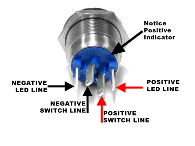
Hello,
I just finished to wire twot bulgin led switch buttons :
http://www.aquatuning.de/product_inf...acts-4pin.html
One white (3.6V) and one green (3.5V).
Can anyone confirm my wiring please ?
Do you know if the hdd and power led voltages output of my motherboard are compatible with the buttons ?
Do anyone have some knowledge on bulgin led buttons please ?
I continued to work on the case last week.
I cut a metal plate from my old case to make a cover for the cable at the back of the case :
I cut a hole for the rheobus and cd rom cables to hide them below :

Wow, enorme la boite ! Honnestly, this case is great, and I really admire the effort put into it, 100% home made. If you're gonna do it, do it big !
It'a a triple triple case...(3x360)
[SIGPIC][/SIGPIC]
i3 530 @ 4.2 ghz, evga FTW, 4 gig gskill trident @ 1600 6-8-6-24, XFX 4870 1gb, corsair 620hx, 2 x kinston 64gig ssd raid0, 300 gig Velociraptor, 2Tb WD green,
Tagan black pearl (lian-li v2000)
Water: mcp655, mcr320 with ultra kazes, GTZ, mcr60, micro-res,
black primochill, bitspower comp. fittings
Well done on the construction of the frame, looks very solid.
Is there any chance you can use counter sunk screws to hold the outside/cover panels on with. I feel it would look less noticeable and more professional.
Looks excellent!
Thanks for the comments.
It'a a triple triple case... (3x360)
I will try that.Is there any chance you can use counter sunk screws to hold the outside/cover panels on with. I feel it would look less noticeable and more professional.
Do anyone have some knowledge on my bulgin led button problem please ?
Your old project becoming popular with this thread. Its simple and clean, thats it. By the way, I like your color out there too. It seems a bit dark but its just fine mate.
Extreme ways I know will part the colors of my sea, perfect color me | Arthur's WC Worklog with Lian Li PC-9
Very nice! I wish I had the skills to do something like this. Also, nice job on the wire management.
AMD Phenom II 955 BE || Asus Crosshair III || Sapphire HD4890 || 4GB G-Skill DDR3 PC12800 || G-Skill 64 GB SSD 2 x 1TB WD Caviar Black HDD
Lite-On DVD-RW || Thermaltake Toughpower 1000W || Silverstone TJ-07
|| WC Parts: HK 3.0 LT || TFC 120.3 || DDC 3.2 w/ EK top || MCW 60 w/ Iandh Ramsinks
Thanks for the picture. I allready know how to wire the button but i don't know if the leds of the buttons can support the led voltage output of my motherboard without a resistance.
Someone on another forum states that his motherboad output 4,4V and the leds of my buttons are rated for 3.5V and 3.6V.
I will mesure myself the voltage output on my motherboard this week.
I'm not particularly skilled.
The frame is really simple to do. You just have to cut the tubes at the right length.
Not That skilled, well,maybe, maybe not, but I think so
However, it does take imagination to think out side the box, and you do have that in spades.
I think i give up on measurements, and wire the buttons like that without modifications.You can't really measure the voltage off of the MB anyway. Regardless, the LED will be fine. (I've never had a problem with them.)
I glued 2cm thick foam panels on the sides and the top for soudproofing.

New photos !

Last edited by Makymaco; 06-13-2011 at 03:37 AM.
Nice to see it up and running
looks nice - rather industrial!
Incredible!
I believe you need a 100 ohm resistor to run this off of 5vdc or 500ohm for 12vdc. At least I use 5mm LEDs with a 100ohm @ 5vdc and it works just fine. Just solder it in line on the positive (long) leg of the LED... My 5mm LEDs are 3.3vdc.
(I hope that's what you were asking)
Current: AMD Threadripper 1950X @ 4.2GHz / EK Supremacy/ 360 EK Rad, EK-DBAY D5 PWM, 32GB G.Skill 3000MHz DDR4, AMD Vega 64 Wave, Samsung nVME SSDs
Prior Build: Core i7 7700K @ 4.9GHz / Apogee XT/120.2 Magicool rad, 16GB G.Skill 3000MHz DDR4, AMD Saphire rx580 8GB, Samsung 850 Pro SSD
Intel 4.5GHz LinX Stable Club
Crunch with us, the XS WCG team

 Posting Permissions


 Reply With Quote


Bookmarks